Volvo 240 1989 User manual

Service
Manual
Faulttracing Design
Repairs Function
Maintenance
TP
31361/1; 12.88
Se
ctio
n 2
(2
3)
lH-
J
etr
on
ic
2.4
fuel
sy
stem
E
ngine
B 230 F
240 1989-19
..

This manual covers the following:
B 230 F
Gasoline engine wi
th
fuel injection and catalyt
ic
con-
erter system.
2.3 titer cylinder volume.
Two valves per cylinder.
LH
2.4 fuel
system
To identify the system with certainty, look for
the
following item (see illustration):
--
"
Diagnostic
socket

Contents
Fuel system
LH2.4
-
240
Contents Page
Specifications..
..
,.,......
..
. ....... 2
Special
tools
.....
..
..
..
.
..
5
Design and
function
-System overview
...........
.,. ........
..
~
,
............,...............,
....
...
6
-Control unit ...... ,....
..
..
......
..
_.... ..............
..
, ....
..
....
..
8
-Sensors ......................................................., ............
..
............
..
........... 11
-Catalytic converter, pressure regulator.... .........
..
............ .... .........
..
...
..
....
..
......... .13
-Injectors, coldlstart valve, fuel pumps. ..........
...
............. ................
..
......
_..
..
...
...
14
-Fuel filter, idle valve. ....
..
..
....
..
........_. .........
..
._
..
..
...... . .....
..
15
-System relay, fuses
..
........
~
....
. ........._.... .......
..
..... ..........
...
..
........._.....
..
...
16
-
EVAP
system.......
_.
.....
..
.....
.
.....
._ ...... , _ .
...
_ ...
..
..
..
.......... . .
..
16
-Diagnostic system...... ..............
..
........
__
..............
..
.........._
..
. ............................ 17
Fault
tracing,
repairs,
maintenance
Detailed table of contents ..................
,.18
Wiring
diagrams
................. ............
..........
_
....
..
..
.....
54
li
he first section of this manual covers the Design and
Function of the fuel system, Reading it will provide
the necessary background for understanding the
second section -Fault tracing, Repairs and Mainte-
nance,
Order
No.: TP 31361/1
We
reserve the right to make alterations
©VOLVO NORTH AMERfCA CORPORATION

Specifications
Fuel system LH2.4 -240
Specifications
Gasoline,
unleaded
Octane requirements:
-RON (Researct1 Octane Number)
91
-95
-AKI Rt M ................................87
2
Air
mass
meter
Volvo
PIN
..
3517020
Bosch PIN.
..
.................
0280212016
Resistance between connectors
2 and 3
...
.
..
.....................
25-4
.0 n
Throttle
switch
Volvo
PIN
..
.................................... 3517068-7
Bosch
PIN
....
.......
..
.
..
..........0 2
80120
325
Con
lr
ol
unit
(part numbers)
Wilh EGR (California)
Volvo PIN ..................
.. ..
...
3501687-2
Bosch
PIN
. ...........
..
..
... 0 280 000 556
Without EGR (remainder of USA, Europe):
Volvo PIN ............................... .... 3517407-7
Bosch
PIN
........... ....................... 0 280 000
561
0
280
160
...
Fuel
pressure
regulator
VolV
OPIN .................
..............
....
3517064-6
Bosch PIN ..................................... 0 280 160 294
Syslem
p
ressur
e (fuel pressure above intake
manifold pressure):
..
.............300 kPa (42 psi)

Specifications
Fuel svstem
LH2.4
-
240
t
o
280
150
Injectors
-Volvo PIN .........
..
.......
..
. .
....
3517572-8
-
Bos
ch PIN................... .....
0280150762
Injeclion capacity 214 cm'lmin at 300 kPa (42 psi)
system pressure.
(Note: use
on
ly spedal equipment to test disas-
sembled injector)
Cold
start
valve Icertain models)
Volvo PIN ....................................... 3517130-5
Bosch PIN...............
..
...........
...
0 280 1
70
264
Injection capa
ci
ty around 165
cmJ
/min.
~
0580464
Fuel
pump
Volvo PIN .......... .
..
..
......... ....
....
1389449-8
Bosch
PIN
...............0 580 464 039
Pumpcapacityal 300 kPa (42 psi) and +20°C (
68
e
F)
:
-12 V .....
..
.
..
.. ..
..............
..
..
....
130 liters/hour
1.0 litersl
30
sec
-
11
V
....
.. ..
108 liters/hour
0.8litersl30 sec
-
10
V
..
...
..
.......
..
..
.......65 Utersthour
0.6 lilers/30 sec
Current consumption at 300 kPa (42 psi). +20·C
(68
°
F)
and 12 V
-ma
xi
mum
..
....... ...........
..
..
........... 6.5 amp
Safety
screen
Fuel
filter
Volvo PIN
..
..
................ 1389450-6
Filters particles down
to
min. of: ... 0.002
IRll
Tightening torque ....
..
......20-35 Nm (15-25 n.I
!»
Tank p
ump
Volvo PIN
..
........................
......
..
.
..
1389721-0
(1317671)
Current consumption .....................
3-
4 amp
3

Specifications
Fuel system
LH2.4
240
o
40000
20000
1
0000
8000
60
00
4000
2000
10
00
8
00
600
400
200
100
,
"-
"-
r-...
.....
r-.....
i'-..
-
30
-
20
0
20
40
60
IKt
100 1
20
'C
-22
-4
32 68 104 140 176 212 248 -F
l!!!2!
Idle valve
-Volvo PIN" "
..
,
..
."
..
"""."",,.,,
1389618-8
-Bosch PIN
."""",,
...
,,"
",,
0280140516
Resistance between terminals
1 and 2
""
""
""""""
""""
""""",,,.
8 n
Coolant
temperature
sensor
-Volvo PI
N.
""".
""
."
"".
""
,,
.,,'
",
1346030-8
-Bosch PIN
,"""""
'"
."
,,
'
"''
''
,,
0280130032
Resistance
in
!ls
at:
-10°C (14°F)
""""""
"",
,,,,
826
0-
10560
+20°C (68°F)
...
"
..
'
''''
''
'''
""".228
0-2720
+80°C (176°F)
",,""""
""""
"",290-364
For other values, see chart,
"'
•
Q
1I
~-----!!.!.
[)
l'
JP=.'::::::I
025
8
003
.
..
Lambda-sand
-
Vol
vo
PIN
",
""""
"""
.,,
""
"
,3501753-2
-Bosch PIN ""
".""
"
"""
"""
"
"""",
0258
003 034
Resistance pre-heating resistor
-cold sond. +20°C (68°F)
".".,,"
""
3 n
-hot sond, over 350°C (660°F)
""
,,
13
n
Tightening torque
"""."
",55 Nm (40 IUb )
Apply "Never Seez" paste (PIN 1 1
61
035-9) to the
threaded section
01
the sond,
4

~'
'''~
; , 1/
"
Special tools
Fuel
system
LH2.4
240
Special
tool
s
999-
Description-use
5011-5 Pressure gauge: indicating
fu
el pressure.
Use
d with 5116, 5265, 5266.
5116-2 Hose:
connecting
pressure gauge
5011.
5151-9
Adaptor:
CO-meter.
5843-1 V
acuum
pump:
check
ing pressure regu l
ator.
6450-4 V
olt
Amp
meter
: f
ault
tracing.
6525-3 Multimeter: volt, a
mp
,
ohm.
diode.
9724-0
Ohm-diode
meter: fault tracing.
9921-0 Volvo Mono-Tester:
sett
i
ng
ignition, idli
ng
speed.
~
Q
~-'<V
~
~
~
515
1
--=
~~
-'"
CO
6450
9724
5

Design and Function
LH-Jetronic
2.4 -LH2.4
~
® C . A
ccomp,
..
w
ltd A rwlte.h
SV
"'"
Iii
P" I II
fel'Y
! t
[]
1t.Wl
~
Idlell
ll
i
ve
@
F
ue
l J
ystam
co
ntr
ol
unit
" Qia
gnosti
c
unit
o Th
rottle
~
_
W
_
'''
_
h
____________
~
Au
mllill
/"'::\2
m
et
er
\.V
~
®~'~
~
CIo
rt.on
~ml.'
h
lomb
...
\)
'ON!
Fuol
hlt_
@)
......
,..mp
RO
."""
~'17'
v
....
~\:.V
Coolant
ro
mp
_
18
nsor
Prim
a
ry
pump
®
The circled numbers
til
the drawing reterto the same
numbers in the following listing,
6

•
De
s
ign
and function
Fuel sy
st
em
LH2.4
-
240
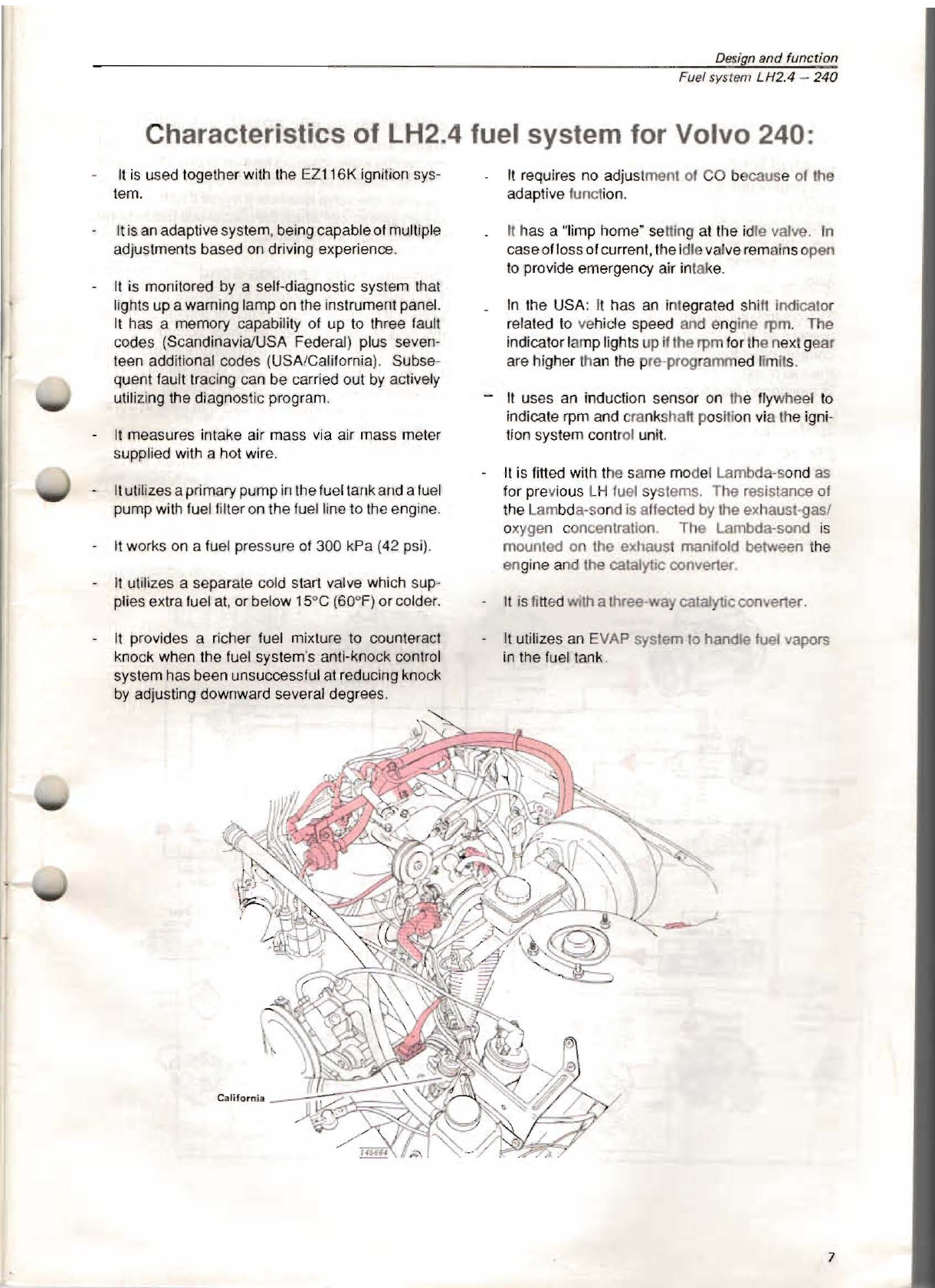
Characteristics of LH2.4 fuel system for Volvo 240:
It
is
used together with the EZ116K ignition sys-
tem.
It
is
an
adaptive system.being capable of multiple
adjustments based on driving experience.
It
is monitored by a self-diagnostic system that
lights up a warning lamp on the instrument panel.
It
has a memory capability of up to three fault
codes (Scandinavia/USA Federal) plus seven-
teen additional codes (USA/California). Subse-
quent fault tracing can be carried out
by
actively
utilizing the diagnostic program.
It
measures intake air mass via air mass meter
supplied with a hot wire.
It
utilizesaprima
ry
pump in the fuel tankand a
fuel
pump with fuel filter on the fuel line to the engine.
II
works on a fuel pressure of 300 kPa (
42
psi).
It
utilizes a separate cold slart valve which sup-
plies extra fuel at.or below 15°C (60"
F)
or cotder.
It
provides a richer fuel mixture to counteract
knock when the fuel system's anti-knock control
system has been unsuccesslul at reducing knock
by
adjusting downward several degrees.
It
requires no adju
st
ment of CO because of the
adaptive function.
It
h
as
a "limp home"
se
Mi
ng at the idle valve In
caseoflossofcurrent. the idlev
al
ve
rema
in
sopen
to
provide emergency air intake.
In
the USA:
It
has
an
integrated shi
ft
Indicator
refated
to
vehicle speed and engine rpm. The
indicatorfamp lights up ifthe rpm for the next gear
are higher th
an
the pre-programmed limit
s.
-It uses an induction sensor
on
th
e
fly
whe
et
to
indicate rpm and c
ra
nk
shaft posi
ti
on
vi
a the igni-
tion system control uni
t.
It
is fitted with the same
mo
del Lambda-so
nd
as
for previous l H fuel
sy
stems. The resistance of
the Lam
bd
a-sond is affect
ed
by
the eXhaust-
gasl
oxygen concentration The Lambda-sond is
mounted on the exhaust manifold between tile
engine and Ihe catalytic conver1er.
It
is
fi
tt
ed
WIth
a three-way catalylJc conver1er.
It
utilizes an EVAP system
to
handle fuel vapors
in the fuel tank.
7

Des
ign
and
function
temperature
sensor
Lambda-
",o
d
ctI;
(
~
.A9'J1riJ
~@ff;;
---1
.
~-
-
Ttuoule
s
wilt::
h
~
-
II
+ -
Ignition
control
Cold
surt
h Auxiliary
'-
-
-W
rela'y
Fu
el system LH2.4 -2
40
Control unit
The control unit has a microprocess
or
that receives
signals from the
var
ious sensors reg
ar
ding
operational condition
s,
evaluates them in relation to
pre-programmed valuas and calculates the correct
injector opening durations
(in
mil/i-seconds p
er
revo-
lution).
The
conlrol unit governs idling rpm by regulating the
amount of aIr by-passing
th
e throttle valv
e.
It also
controls other functions, s
uc
h as the cold start valve,
the fuel pump and
th
e relay. One impo
rt
ant function
is monito
ri
ng fault fracing via the diagnostic socke
t.
Self-adjusting functions
Thecontrol unit is adaptive in that it adjusts
it
s calcu-
lations according to assimilated input.
Sell-adjusting Idle speed regulation
In
time,w
ea
r and coatings will affect the operation of
the thr
oH
le valve, causing less
aI
r
to
ent
er
the intake
system. Instead
01
working from a pre-programmed
value the idle valve receives a signal that is adapted
to theexperiences which the control unit has learned
from previous driving periods.
Self-adjusting Lambda-sand
The Lambda-sond operates
in
a similar fashion.
It
senses
if
the fuel mixture is rich or lean and adjusts
the control unit's Lambda regulat
or
accordingly.
The self-regulatingmechanism keepsthe control unit
function at midpoint. This does away with the
need
to adjust the CO content and automatically compen-
sates for the effects of tolerances and wear
in
the
in
-
jection syste
m.
Whe
never
th
e vehicle is started and driven, the con-
trol unitwill use the value that has been learned from
previous driving periods.
8

Design
and
function
Fuel system
LH2.4
-
240
The
control
unit
microprocessor
receives:
Exhaust gas oxygen content information from the
Lambda-sand.
Rpm and crankshaft
po
sition information from the
ignition system control unit. If this information
is
not forthcoming, the fuel system control unit will
not function.
Engine temperature information from the coolant
temperature sensor.
Engine load information from the air mass meter.
Information from the shutter switch as to whether
the
th
rottle shutter
is
closed or
wi
de
open.
El
ectrical system voltage from
th
e battery current.
The signal from the AC switch info
rm
s if it
is
on,
and the signal from the compressor connection
indicates that the compressor
is
operating.
Emergency
program
There
is
a "limp home" function provided
if
the signal
from the air mass meter ceases for some reas
on,
such as the hot
wi
re
bu
rn
ing off. A p
re
-programmed
value
is
used
fo
r Injection duration, allowing
th
e
vehicle
to
be driven slowly to the garage.
The
control
unit
microprocessor:
Sets the voltage of Ihe
sy
stem by grounding the
system relay.
Breaks the s
ys
tem relay ground
if
engine turns
ova
rtoo
slowly (engine has stopped). This keeps
the battery trom being drained and cuts off fuel
fl
ow from the fuel pump when the engine isn't
in
op
eration.
Grounds Ihe injectors, which regulates opening,
liming and injection duration.
Controls air valve tor constant idle speed (CIS).
Is
connected to the diagnostic
un
it and provid
es
fault information about the various functions.
Provides the ignition system control unit with load
intormation.
Protects against too high rpm by shutting
oH
fuel
injection until the engine has stowed down.
USA/Canada:governs
CH
ECK ENGINE warning
lamps and shift indicator lamp.
r-------------------------------------
----4
.
r------;:;:;:=~===
·
~~:~m
8
6
1
2
!Ir--------
15
I
~
=--
Rpm
.....
r-,-d,-.-""""L..J-
----
r:':
lJ
Ignition
5Y5tem
control
unit
0
..
"
.-----'~,
I 3
"'--
Full
load
--.
0
20
I
"'
12
_--,
L-
_______
_
21
1
~
31/
1"'--
1
~
41'"_
........
"'Sattery +
Throttlll
K -
~
--e
lZ
I 5 • ;
...
. 1
switch
~KIJ
!....I
.......
•
23
1
~
_
=
-I
=-O}o
24
1 6 . • 2 .
.r=..
';;~
="=-=='-
:!.~
•
25
1 7 ' • 3
(\'¥-,-
--
,
L.
__
Cr&nksh!tfl
posit
i
on
_ ,
\.?
__
Shift
indicato
r n
-------e
2ti
I 8 I • 4
Ai
r m
ati
Diagno
tti,
I,
L...I •
21
1 9
~
r 5
meter
un
'
t
...
..
.
~
"'
L-
_ _ K
nock
e
nflchm6
"'
~
10 •
S,m.,
/
so
4
~
11
~
-
-
---
"'-
--
'1
---
~::
"
.
~
V 1
12
Coolant
b
~
¥ 30
,~'
AC
<omp""'o,
1
13
• . '
_I
I
tem
peratu
r
lr
Cold
start
f .
31
1
sensor
~~
",..
t ,
321:
:: : ' tAC
'
W
~.:.:::
:
h
:'
,.
r=;':":'
::..:
::::
'
1
':
, . •
331
:r
~
,1
16
._
\\
~\.
---+\---+-,
~
:."
~
.
~
:,1
17
:J
~
~
"'
~
\.
~,
",/
,
r-
'E-x.,,-
1
18
k.::..
....
@
I
die
waive
---....:
-~
--
9

De
si
gn
and function
Fuel system LH2.4 -
240
Th
e
start-
up program provides for two injection
durations per revolution.
The
co
ld-sta
rt
valve is activated when the tem-
perature
is
at-15°C(5°F) or below,and
th
eengine
speedis under
ap
proximately 900 rpm. Once the
rpm exceed the pre-programmed limit, the cold-
start valve Is turn
ed
off.
======>
'"
~
------------
During
nor
ma
l
driving
conditions, injection dura-
tion is regulated mos
tl
y with referen
ce
to signals
trom
th
e air mass meter.
The
choke
provides a richer fuel
mi
xt
ure
to
th
e
engine
up
to
an
engine temperature of 60°C
(140"F).
Inj
ec
ti
onduration increases during acceleration.
Knock
enrichment
provides a
ri
cher fuel mixture
to
cou
nt
e
ra
ct
kn
ock when the fuel system's anti-
knock contr
ol
system has been unsuccessful at
reducing knock by adjusting downward seve
rat
degrees on all cylinders. Knock cause high
com
bu
s
ti
on temperatures. When knock occurs,
th
e control unit increases the amount of fuel in
order bring
th
e combus
ti
on temperature do
wn
and reduce
th
e knock.
Excess rpm
is
prevented via a rotation speed
limiter which turns
011
the injectors. They are
turn
ed
on
again when the engine rotation
is
re-
du
ce
d.
At
full
load, a
ri
cher airlluel mixture is used
to
provide maximum engine powerand tolessen the
el1ects ofcombustion heat
on
th
e engine and the
catalytic
co
nverter.
During deceleration, fuel injection
is
discontin-
ued above 1,800
rpm
in
all
gears.
It
is
resumed at
1,400
to
2,000 rpm, depending
on
engine tem-
perature.
10

Design
and
function
Fuel system I.H2.4 -
240
Air mass meter
Measures engine inlake
ai
r mass. Those factors
whichaffe
ct
air densi
ty
,such
as
temp rature,humid·
ity and ptessute (altitude) elc. are laken inlo consId-
eration during measurement.
The measurement sensor insi
de
Ihe air mass meter
consists
of
a wire which
Is
maintained
at
1
2.0
"C
(2.S0
DF) (previously
IOO"C
-(215'F
) hig
he
r tllan tile
ambient air entering the engine. As the air mass
passing over the wire incre
ase
s.
more currenl is
r
eq
uired
to
maintain the correct
te
mperature.
Th
e
amount ofcurrent required
Is
used
to
catcula
te
the air
mass taken
In
.
When
th
e engine
is
tu
rned
oN
, any dirt on the wire is
burned oN electrica
ll
y by heating the wire
to
over
1000' C
(tBOO
'
F).
Any dirt remaining
on
the wire
would cause it
to
send incorrect information
to
the
co
ntrol unitand result In an Incorrect f
ueUair
mixture.
Protective
grille
Earlier mode
ls
of the air mass meter were provided
wi1h
an adjustmentscrew for CO
seNi
ngs. However.
because the
LH2.
.4 Lambda-sand
is
self-adjusting
this screw
is
no longer necessary.
o
Coolant temperature
sensor
Provides the control unit with information regarding
the engine temperature necessary
fo
r
pr
oper adjust-
ment of injection duration.
11

Design
and
function
Fuel system LH2.4 -
240
Obt0
09
mount!",
bol.-
to
r
adjunino
Iw
he
h Mtting
Fuili
olid
switch
~
Throttle
__
--~
~-"i
~r&2])IS
spindle
C.m
disc
Idle switch
(micro
SWiTCh)
Heatin':..-.J
t...-
H-
=
n.m
Sensor
The exhaust gases reach the outer surface of the
Lambda"sond sensor via slits in the protective
sleeve. Ambient air reaches the sensor's inner
surface via channels. The sensor itself consists of a
pfatinum covered zirconium-oxide pipe.
The Lambda-sond signal strength
is
in direcf propor-
tion
to
the amount of oxygen in the exhaust gases.
Thisdepends
on
the airlfuel ratio. ALambdavalue of
1 represents the theoretically perfect ratio. A rich
mixture results in a higher voltage and a lean mixture
gives the opposite result.
The current sent by the Lambda-sond to the control
unit varies between
0.1
and 1.0 volt.
The shift between high and low voltage occurs when
the Lambda value
is
at
1.
The control unit uses this
information
to
adjust the amount of fuel injected.
o
Throttle switch
Tells the fuel system and ignitionsystemcontrol units
whether the throttle valve is closed or fully open.
o
La
mbda-sond
Under normal conditions, the optimum mixture ratio
is 14.7kg air
to
1
kg
fuel. The ratio
is
monitored by
post-combustion measurement of the oxygen con-
tent
in
the exhaust gas using the Lambda-sond.
This particular model of Lambda-sond is known
as
a
"comparing Lambda-sond'. It produces a measure-
able current
by
comparing the amount of oxygen in
the exhaust gas with the amount
in
the ambient air.
The Larnbda-sondoperatesonly within acertaintem-
perature range -approx. 285-850°
C,
(545-1530°F).
It
is
electrically
heated
to
enable
it
to
reach operat-
ing temperature quickly. When the ignition
is
turned
on, current
is
sent
to
a PTC resistor (Positive Tem-
perature Coefficient) whose resistance increases
with rising temperature. Because of this system, the
Lambda-sond quickly reaches correct operating
temperature, even at low exhaust gas temperatures.
The
Lambda
·sond is mounted in
th
e exhaust
gas
mani-
fold about
15
cm
(6
in.)
in
front of the catalytic
co
nverter.
12

Design
and
function
The catatytic converter cleans the exhaust gases in
three
ways
:
1 - by incinerating unburned hydrocarbons (HC) at
high temperature, releasing
th
e
re
sidue
as
steam (H,O).
2 -
by
converting carbon oxide (CO)
to
carbon dio
x-
ide (CO,) through oxidation.
3 -
by
reducing nitrogen oxides (NO
,)
to
gaseous
nitrogen (N).
90
to
95% of the dangerous gases are rendered
hamnless.
o
Di
stribution pipe
Theincoming fuel feed line,pressure regulator, injec-
tors and cold start valve are connected
to
th
e
di
st
ri
-
bution pipe.
Fuel system
LH2
.4 -
240
Catalytic converter
In
order
to
be
able
to
operate as inte
nd
ed,
th
e
catalytic converter
is
dependent
on
correct informa-
tion from the Lambda-sand. The air/
fu
el
mi
xture must
be
adjusted
so
that fuel
is
completely burned in the
engine prior
to
the exhaust gases reaching the cata-
lytic conve
rt
er.
The
co
nverter can bedamaged through ove
rh
eating
if
unburnt
fu
el
is
emitted in
th
eexhaustwhere oxygen
is present.
This can happen
if
a large amount of unburnt fuel
reaches the catalytic converterprior
to
starting. It can
also happen if there
is
a loose ignition cable, and a
cylinder pumps unburned fuel into the exhaust.
Lead
in
the fuel will quickly aHect the
La
mbda-so
nd
and cause the exhaust
ga
s cleaning function
to
stop
working.
If
tllis happens,
th
e
La
mbda-sond wi
ll
stop
providing the information needed
by
the control unit
to
set the fuel mixture and the
cataly~c
oonverterw
ill
then be destroyed.
The active area is about 20,000 sq. m (215.000
sq.
ft.). (Cali
fo
rnia EGR converter approx,32.000
sq.
m
~
34
5,000sq,fl.) Thepreciousmetalcontentisabout
2 grams (.07 oz)
of
platinumlrhodlum,
®
Fuel
press
ure regulator
The fuel pressure regulator ensures t
ha
t the fuel
pressure remains constant at the
In
jectors. Using a
vacuum tube connected
to th
e eng
in
e Intake man
i-
fold, the fuel pressure is kept at 300kPa
(4
2 psi)
above (below) the intake manifold pressure. In this
way the pressure over the injectors is kepi constant,
regardle
ss
of throttle
pOSition
. The amount
of
fuel
injected depends entirely
on
the Injection duration.
Excess fuel is returned
to
th
e fuel lank via a return
pipe.
(
13

Design and function
Fuel system
LH2.4
-
240
o
o
280
1
50
...
..
Vi!llv
e
pump
Tank
pump
Injectors
The injector is
fin
ed with a solenoid, a magnetic
actuator and a fuel needte which opens or shuts a
nozzle.
The
control
unit feeds c
urrent
to
the injectors
in
ca
lculated
time
units. This ensures
that
all
the injectors spray a fine fuel mist simultane·
ously.
While
the
starter motor
is
opemting,
th
e
re
are two
injeclions p
er
rotalion. Th
is is
reduc
ed
to
one for
norm
al
d
ri~
i
ng.
Injectionoccurs in the intake manifold
ne
ar the intake
~alves.
Disassembled injectors should only
be
inspected
using specially designed equipment in order
to
mini-
mize the
ri
sk of explosion from fhe
fu
el mist.
Cold start valve (
eenail!
mod
els)
At cold start, a lot
01
fuel condenses
on
the cold
surfaces in the lorm of
dr
oplels. Having a separate
cold start valve improves cold starting.
It'
s placed
farther away from the engine block than the ordinary
injectors and delivers the fuel more as a gas Ihan as
drops. The cold slartvalve
is
controlleddirectly
by
the
conlrol unit, ralher than by the thermal time
swifCh
.
It
culS
in
when the temperature
is
aboul -15cC
(5
°
F)
and when Ihe engine rolation
is
below approx. 900
rpm.
It
culs out permanently
if
the rpm exce
ed
the
permissible limit.
®
Fuel pump
The fuel pumpis
an
eleclric rollerpump,cooled by the
fuel which flows through
it.
It
has a non-return valve
and
an
overflow valve which opens if the pressure
gels
100
high.
Both
th
e primary pump
an
d Ihe fuel pump operate
wheneither the
st
artermotororIheengine
is
running.
However, should the engine stop while Ihe ignition
remains
on
, the conlrol unll
wi
ll cut off the current
to
th
e
pu
mps in order 10 eliminate Ihe risk of fire in Ihe
even! of
an
acciden
l.
@
Tank pump (pre-pump)
The electric
Im
peller pump in the fuel tank keeps
pressure in the fuel
lTne
prior to the (main) fuel pump
to prevenl vapor lock.
The pump hasa coarse,slralnerIypefilter and anon-
return valveto maintain acertain amounl of pressure
in
th
e system even if the main pump is not in
operation.
14

Safety
scre8n
When the throNle valve switch is closed during idling,
the control unit receives a signal, enabling
it
to
send
current
to
the air valve electric motor
to
keep the idle
rpm at the correct level.
Des;gn
and
funct;ol].
Fu
el
sys
t
em
LH2.4 -
240
@
Fu
el f
il
ter
The luel filter
is
adjaoentto the fuel pump and both are
mounted
on
a plate below the vehicle underthe back
se
at.
Itconsistsof apaperfilter and asafety screen
to
catch
any pieces of the paper filter which come loose.
Idle valve
,
In
order to set the correct air valve opening and thus
achieve constant idte speed, the control unit uses in-
formation from the air mass meter regarding the
amount of air entering the engine and from the
ignition system control unit regarding rpm. This
means that the idle valve is not affect
ed
by air leaks
or a jammed throttle valve.
When the current
is
off, a spnng sets the idle valve
opening for an idle speed between 1.
000
and 1,100
rpm.
Once the engine
is
running, the control unit ensures
that the idle valve is more
or
less open
al
a
ll
rotation
speeds in order
to
preventthedevelopmentofunnec-
essarily high negativepressurein the intakemanifofd
when the throttle shutter closes suddenly during
deceleration.
The control unit receives a signal from the AC control
when the
AC
is
tumed on oroff
to
enable it
to
adjust
the idle valve. Signals are alsosent
to
thecontrol unit
from the
AC
compressorso that the idle valve can be
adjusted each time the compressor turns on or off.
..
There
is
no
signal
to
the control unit when the shuNer
switch
is
open. When driving, the control unit keeps
the idle valve partially open so that the negalive
pressure
in
the intake manifold
is
reduced when the
gas pedal
is
released.
15

Design
and
function
Fuel system LH2.4 -
240
Igniti
on
system
contol
unil
FUIII
system
control
unit
SYltem relay
iQ:::='J
~
Stl,-===
~~/
fJ
I)
Carbon
.
fihM
System relay
Gove
rn
ed by the contr
ol
unit,
it
provides current
to
the fuel pum
p,
the injector
s,
the
cold start valve,
the
air mass meter and
to
certain control unit functions.
The system relay and its functions are protected by a
20
amp fuse.
Fuses
The system relay
is
protected
by
a 25 amp fuse and
the tank pump
by
a
15
amp fuse .
Evaporative Control System (EVAP)
This
sy
stem handles the gases that result Irom nor-
mal fu
el
lankevaporation, keeping Ihem from escap-
ing and pollu1ing
th
e air.
Via a hose system, the luel vapor passes from the
filler opening throu
gh
a roll-over valve
to
a reservoir
("canister', "carb
on
IIfter-). The fuel vapor
is
absorbed here. n
1e
reservoir
is
provided with
an
EVAP valve
wh
ich prevents leakage of fuel vapor
while
the
en
gine is not in operaHo
n.
®
Reservoir
(carbon IIIter)
The
fu
el
vapors f
ro
m
th
e fuel tank enter the top of the
active ca
rb
on filter and are absorbed. Air
is
pushed
out through a channel in the bottom of the filter.
Depending on tempera
tu
re
and otherconditio
ns
, the
filter can bind approx. 90 grams of fuel.
®
R
oll-ove
r
valve
If the
ve
hicle leans sideways at more than a 45'
angle, this valve closes, helping to prevent fuel spills
during accidents.
@)
EVAP valve
This valve
is
located
at
the top of the carbon filter and
is closed when the engine
is
turned off.
It
's also
closed during idling in order not
to
interfere with the
automatic idle settings or make the fuel
mi
xture too
rich. The
va
lve
is
closed using vacuum pressure
taken Irom the intake manifold and through being
connected
to
the throttle shutter
po
sitive terminal.
Increased engine load opens the EVAP valve,allow-
ing fuel vapor to flow from the carbon filter into the
engine intake manifo
ld
. Air
is
drawn in at the same
time through the bottom channel. Under normal
conditions, the filter is empti
ed
of
fu
el in 15
to
20
minutes.
16

Des
ign
and
function
Fuel system LH2.4 -
240
®
Fuel system diagnostics
The fuel system has a built-in self-diagnostic system
and a funclions testing system_
It
uses the same
diagnostic socket as the ignition system and Is lo-
cated behind the
Ie"
spring strut tower in the engine
compartment.
The
di
agnosticsystemusessocket2
fo
rthe fuel sys-
tem and socket 6 for the ignition syste
m.
There are eighteen different fault codes in the diag-
nostic system.
It
is
capableof storing
up
to
three fuel
system faults.
The fuel system control unit carries out continuous
checks of the following functions while the engine
is
running:
-The control unit's own internal functions.
-Lambda-sond and Lambda settings.
-Coolant temperature sensor.
-Air mass meter.
-Battery voltage.
-Throttle shutter.
-Ignition settings and engine rpm (through Ihe
ignition system control unit).
-Speedometer.
-Knock indicator.
-Idle speed air valve.
-Injectors.
Faults
in
any
of these funclions are registered
in
the
diagnostic system memory.
17

The Design and Function
01
the luel system has been
described on the preceding pages.
II
is
important
to
read
them
il
you are
to
have a
dear
understanding
01
the next
section.
Fault tracing -Repairs -Maintenance
CONTENTS
Important!
.........
Group
20 General .......
Page
.
.......
_ .
..
.......... 19
.
....
_....... ........
21
Grou
p 23 Fuel
system
• Placement
of
components
.........
..
..............
..
22
•
Fa
ult
tracIng .........
..
.... ......
......
..
..
24·31
Function
AI·A15
Complete
overview
01
the
luel
system
.
-Fuses, grounding connections, connectors .....32
·
Air
leakage and throttle shutters ......................33-34
• Pumps, pre
ss
ure regulator, fuel lines ....... .......
35
·
37
· Components,
cabling.
..
.............
..
...
38·50
81 -
84
Cl·C6
Dl·D6
E
l-E28
· Quick check of injectors ...
51
Fl
• Injectors, luel distribution pipe
and pressure regulator
....
....... ......
....
........
52
18
Table of contents
Other Volvo Automobile manuals

Volvo
Volvo S60 2013 Quick start guide

Volvo
Volvo PV 544 User manual

Volvo
Volvo S60 - ANNEXE 931 User manual

Volvo
Volvo 2010 S40 User manual

Volvo
Volvo XC 60 User manual

Volvo
Volvo S60 - ANNEXE 931 User manual

Volvo
Volvo S40 2006 User manual

Volvo
Volvo C30 2012 User manual

Volvo
Volvo S40 2005 User manual

Volvo
Volvo XC40 RECHARGE User manual

Volvo
Volvo S80 2014 User manual

Volvo
Volvo V90 - ACCESSORY PANEL User manual

Volvo
Volvo XC70 2014 User manual

Volvo
Volvo 164 User manual

Volvo
Volvo C70 User manual

Volvo
Volvo S90 2019 User manual

Volvo
Volvo FE User manual

Volvo
Volvo C70 User manual

Volvo
Volvo V90 CROSS COUNTRY User manual

Volvo
Volvo V60 Cross Country User manual