manuals.online logo
Brands
  1. Home
  2. •
  3. Brands
  4. •
  5. Von Duprin
  6. •
  7. Power Supply
  8. •
  9. Von Duprin PS914 User manual

Von Duprin PS914 User manual

*44487056*
44487056
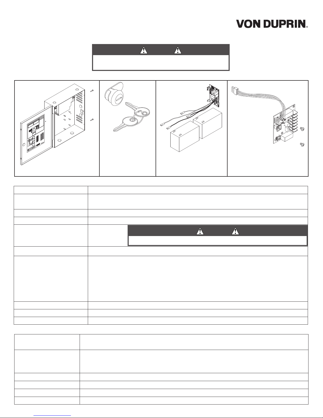
These instructions cover the following parts:
Input 120/240 VAC, 1.4 A, 50/60Hz, High Voltage Class 1 Wiring Required
Output 4 Amp DC @ 12/24 VDC
May be used to power Von Duprin & Falcon EL device at 24VDC, 16A, 300ms
Enclosure 14” H x 12” W x 4” D (8 knockouts, 1/2” or 3/4” )
Temperature Range 32°-120° F (0°- 49° C)
Fuse F1, T6.3A
250 VAC
Compliance UL 294, ULC-S318, RoHS, & FCC Part 15, Class 2 Output
Compatible Boards
(Optional, 2 boards maximum)
900-2RS
900-2Q
900-4R
900-4RL
900-8F
900-8P
Fire Alarm Input Board (Optional) 900-FA (Requires one option board above)
Battery Backup Board (Optional) 900-BB
AC Monitor Output Form C Contacts, 30 VDC, 1 Amp, Resistive Load
PS914 Power Supply Specications:
INST. INSTRUCTIONS - 44487056
INST. INSTRUCTIONS - 44487098
INST. INSTRUCTIONS - 44487106
INST. INSTRUCTIONS - 44487080
INST. INSTRUCTIONS - 44487106
INST. INSTRUCTIONS - 44487072
INST. INSTRUCTIONS - 44487064
Inputs I1,I2 Dry contacts required (Closed = Active)
Connect control contacts between SC (Signal Common) and any input
Outputs O1,O2 • 12/24VDC, 3A (wet) when AC powered • 9.6-13.2VDC or 19.2-26.4VDC when battery powered
• May be used with PS914 to power EL device at 24VDC, 16A, 300ms
• Maximum load cannot exceed power supply ratings or 3A for outputs combined
Board Input Power Board requires 0.1A max. of power supply output current to operate
Temperature Range 32°-120° F (0°- 49° C)
Compliance UL 294, ULC-S318, RoHS, & FCC Part 15
Fire Alarm Input Accepts 900-FA Fire Alarm Board (Optional)
900-2RS Specications:
900-BB Battery Backup
(optional)
Page 3
900-2RS (optional) - Page 4
(2 Zone EL Control -
Individual/Sequential)
900-KL Keylock
(optional)
Page 2
PS914
Power Supply
Pages 1-3
F1
DANGER
!
!
DANGER:
!
WARNING:
!
WARNING:
Power Supply
PS914
Installation Instructions
DANGER
To avoid risk of electric shock, turn off AC power before
installing or servicing PS914 power supply
CAUTION
For protection against risk of re, replace fuse with same type and rating
1 Mount power supply
1a Mark 2 Top Holes 1b Secure Enclosure with 4 Screws
Mounting notes
The PS914 must be installed in accordance with the article 760 of the National Electrical Code or NFPA 72, Canadian Electrical Code, or
any other applicable codes.
Install the PS914 indoors within the protected premises.
Check national and local codes for additional installation requirements.
Enclosure must be rmly mounted to a solid surface using hardware suitable for the surface.
xx
2 Secure enclosure door
If No Keylock
Enclosure will be secured with 2 screws
as shown (done as last step)
If Keylock
Remove knockout and insert key cylinder, then slide in clip
ab
OR
Board not shown for
clarity
3 PS914 setup and testing
F1
DC Output
(Red LED)
12/24 VDC
Output Terminals
AC Input
(Green LED)
AC Monitor
Active when AC
present and F1
fuse not open
(Form C dry
contacts)
NC C NO
24
12
900-BB Connector
3a
NEU
LINE
Green (Ground)
White (Neutral)
Black (Hot)
AC (In)
120/240
VAC
AC Input
OR
12 VDC
Output Setting
24 VDC
Output Setting
Minimum of 1/4” separation
between AC and DC wiring as
well as power limited and non-
power limited.
Note:
4 Install 900-BB battery backup (if included)
1a Place Batteries in Box withTerminals
to the Left
1b Attach Wires from Battery Board
Red wires = (+)
Black wires = (-)
Note: Allow 24 hours for batteries to fully charge
Battery 1 Battery 2
Black Wires = (-)
+
+
BB LED
(Amber)
On-Solid
AC On
Batteries
Charging
On-Blinking
AC Off
Batteries
Supplying
Power
Battery Supervision Terminals
(Form C Dry Contacts)
Active
AC On
Inactive
AC Off
(Shown
AC Off)
NO
C
NC
Red Wires = (+)
Refer to 900-BB instructions for additional
info
5 Turn on AC breaker to test power supply
• Verify AC LED is On = GREEN
• Verify DC LED is On = RED
• Verify BB LED (if applicable) is On = AMBER
DANGER
Ensure AC breaker is turned off
3a Connect AC Wiring
3b Use Jumper to Select 24 VDC or 12
VDC Output
DANGER
High Voltage
If main board must
be removed, turn off
AC power and wait
8 minutes before
removal. Do not
remove this cover, no
servicable parts
DANGER
If AC LED is off, turn AC breaker
prior to checking F1 fuse
6 Install 900-2rs option board (if required)
7 Connect wiring to 900-2rs option board
Sequential Mode - Typical Wiring
Input I1 will activate both outputs
Individual Mode - Typical Wiring
Input I1 will activate output 1
Input I2 will activate output 2
EL Device 2
(not polarized)
Access
Control
for Device 2
EPT-2/10
EL Device 1
(not polarized)
Access
Control
for Device 1
EPT-2/10
SC I1 01 I2 02 GND
2RS
120/240 VAC
50/60Hz
A
B
A
B
EL Device 1
(not polarized)
Access
Control
for
Devices 1 & 2
EPT-2/10
EL Device 2
(not polarized)
EPT-2/10
SC I1 01 I2 02 GND
2RS
120/240 VAC
50/60Hz
A
B
A
Note:
Fail secure output only
allowed if approved
by Authority Having
Jurisdiction
OR
Sequential Individual
Option 2
Option 1
12
If installing board in location 2, rotate board 180˚
Note: 24VDC output setting required when EL
device connected
NOTE: WHEN INSTALLATION IS
COMPLETE, SECURE ENCLOSURE DOOR WITH
SCREWS OR KEYLOCK
Wire Ga
(AWG)
Device Current
(Amps DC)
Output*
(max. ft)
Input
(max. ft)
14 0.3 850
0.5 500
18 0.3 340 1200
0.5 200
12 Using EL device with EPT or Door Loop
(PS914 required)
200
14 100
12 Using EL device with Electric Hinge/Pivot
(PS914 required)
150
14 75
Wire table (suggested maximum)
*Wiring allows for 10% voltage drop at device current at 12 or 24VDC
Max. ft = one way distance between power supply and device
8 IF PS-914 has other option boards, see their
instructions
© Allegion 2014
Printed in U.S.A.
44487056 Rev. 01/14-b
Customer Service
1-877-671-7011 www.allegion.com/us
6a Use Jumper to Select Function
6b Plug 2RS Cable into any Available
Option Connector
6c Secure Board with Screws
DANGER
Ensure AC breaker is turned off when
installing or wiring option boards

Other manuals for PS914

1

Other Von Duprin Power Supply manuals

Von Duprin PS914 User manual

Von Duprin

Von Duprin PS914 User manual

Von Duprin PS873 Service manual

Von Duprin

Von Duprin PS873 Service manual

Von Duprin PS9 SERIES User manual

Von Duprin

Von Duprin PS9 SERIES User manual

Popular Power Supply manuals by other brands

Venitem TUL 135 installation manual

Venitem

Venitem TUL 135 installation manual

Diamond Antenna GZV6000 instruction manual

Diamond Antenna

Diamond Antenna GZV6000 instruction manual

Meanwell SHP-10K-HV Series installation manual

Meanwell

Meanwell SHP-10K-HV Series installation manual

I-Tech IT6700 Series user manual

I-Tech

I-Tech IT6700 Series user manual

OmniOn Power CPS6000 II Series quick start guide

OmniOn Power

OmniOn Power CPS6000 II Series quick start guide

StarTech.com ATX2POW450HS instruction manual

StarTech.com

StarTech.com ATX2POW450HS instruction manual

Kenwood PD8-20 Service manual

Kenwood

Kenwood PD8-20 Service manual

Tru-Test Unigizer 12000i user manual

Tru-Test

Tru-Test Unigizer 12000i user manual

Chroma Color Block PSU30 user manual

Chroma

Chroma Color Block PSU30 user manual

Horizont S40 instruction manual

Horizont

Horizont S40 instruction manual

Xantrex XPR 10-600 operating manual

Xantrex

Xantrex XPR 10-600 operating manual

Natec NHZ-0369 user guide

Natec

Natec NHZ-0369 user guide

Optimal Power OPR200-48S manual

Optimal Power

Optimal Power OPR200-48S manual

Keithley 2230 Series quick start guide

Keithley

Keithley 2230 Series quick start guide

Akyga AK-ND-58 user manual

Akyga

Akyga AK-ND-58 user manual

eFUEL SK-200017 instruction manual

eFUEL

eFUEL SK-200017 instruction manual

Sven USB CHARGER user manual

Sven

Sven USB CHARGER user manual

Gold Note PSU-10 EVO owner's manual

Gold Note

Gold Note PSU-10 EVO owner's manual

manuals.online logo
manuals.online logoBrands
  • About & Mission
  • Contact us
  • Privacy Policy
  • Terms and Conditions

Copyright 2025 Manuals.Online. All Rights Reserved.