1 of 4
These instructions cover the following parts:
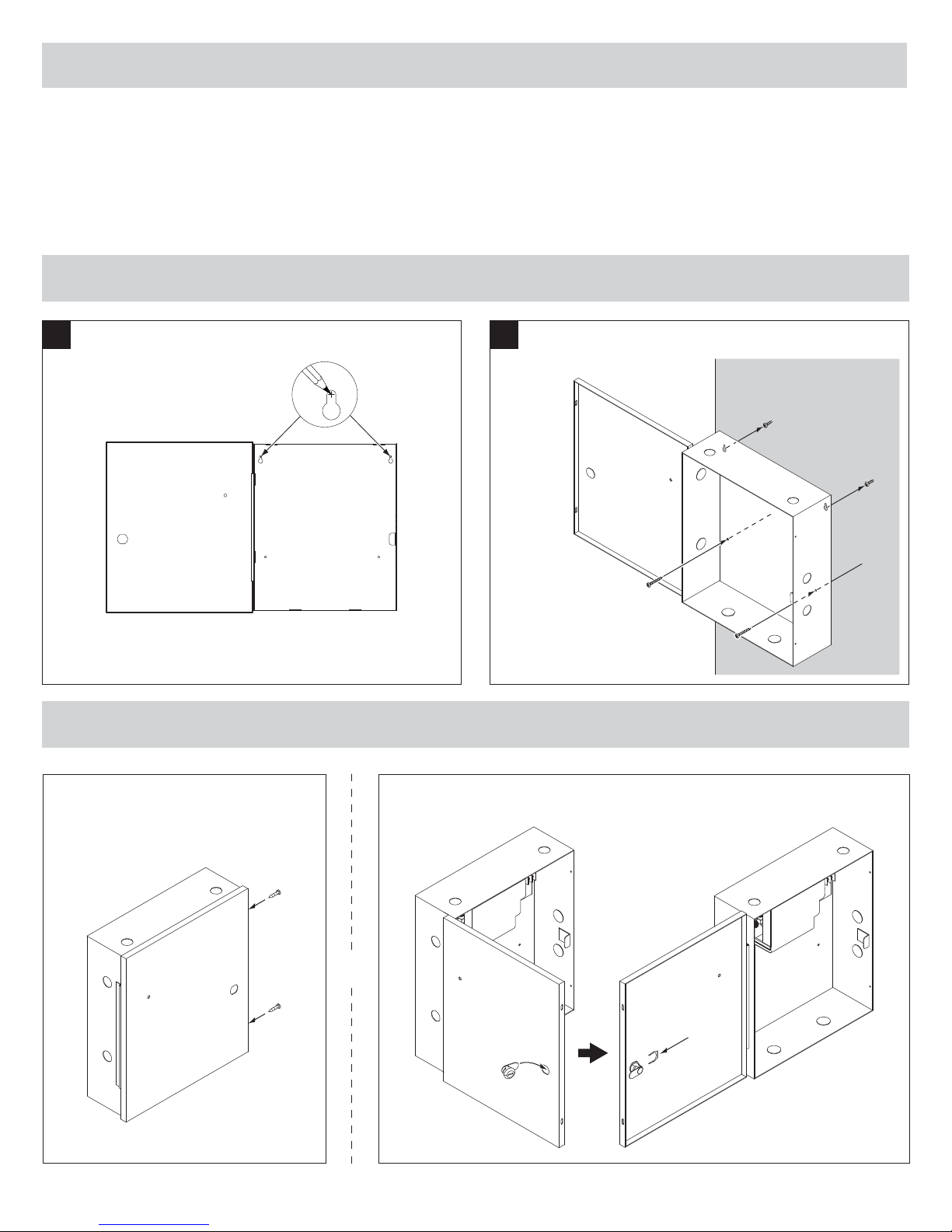
Installation
Instructions
PS914 Power Supply
© 2010 Ingersoll-Rand Company
1-877-671-7011
44487056 Rev. 10/10_a
44487056
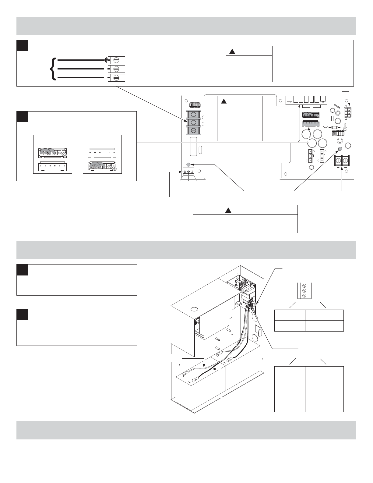
To avoid risk of electric shock, turn off AC power
before installing or servicing PS914 power supply.
DANGER:
!
PS914 Power Supply Specifications:
Input 120/240 VAC, 1.4 A, 50/60Hz, High Voltage Class 1 Wiring Required
Output 4 Amp DC @ 12/24 VDC
May be used to power Von Duprin & Falcon EL device at 24VDC, 16A, 300ms
Enclosure 14” H x 12” W x 4” D (8 knockouts, 1/2” or 3/4” )
Temperature Range 32°-120° F (0°- 49° C)
Fuse F1, T6.3A
250 VAC
Compliance UL 294, ULC-S318, RoHS, & FCC Part 15, Class 2 Output
Compatible Boards
(Optional, 2 boards maximum)
900-2RS
900-2Q
900-4R
900-4RL
900-8F
900-8P
Fire Alarm Input Board (Optional) 900-FA (Requires one option board above)
Battery Backup Board (Optional) 900-BB
AC Monitor Output Form C Contacts, 30 VDC, 1 Amp, Resistive Load
For protection against risk of fire, replace fuse with same type and rating
CAUTION:
!
INST. INSTRUCTIONS - 44487056
INST. INSTRUCTIONS - 44487098
INST. INSTRUCTIONS - 44487106
INST. INSTRUCTIONS - 44487080
INST. INSTRUCTIONS - 44487106
INST. INSTRUCTIONS - 44487106
INST. INSTRUCTIONS - 44487072
INST. INSTRUCTIONS - 44487064
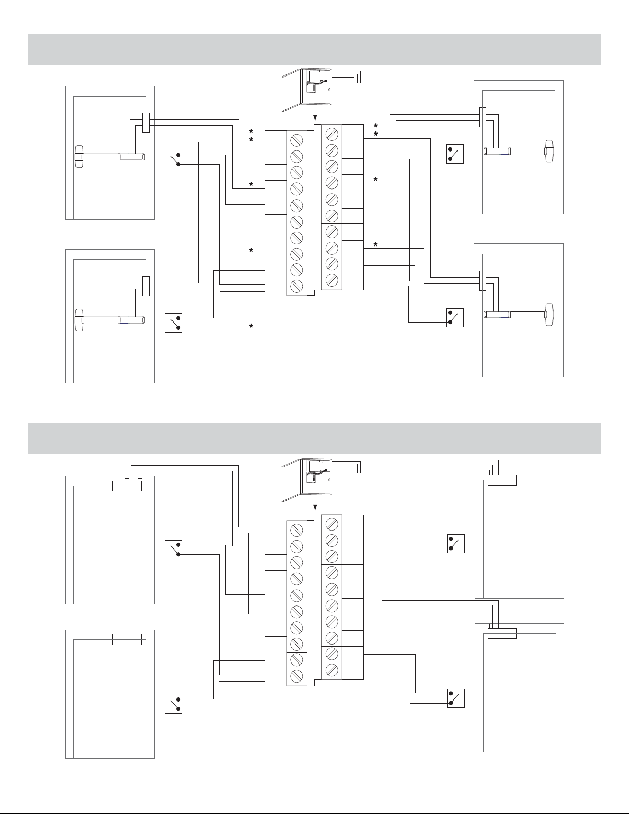
Inputs I1,I2 Dry contacts required (Closed = Active)
Connect control contacts between SC (Signal Common) and any input
Outputs O1,O2 • 12/24VDC, 3A (wet) when AC powered • 9.6-13.2VDC or 19.2-26.4VDC when battery powered
• May be used with PS914 to power EL device at 24VDC, 16A, 300ms
• Maximum load cannot exceed power supply ratings or 3A for outputs combined
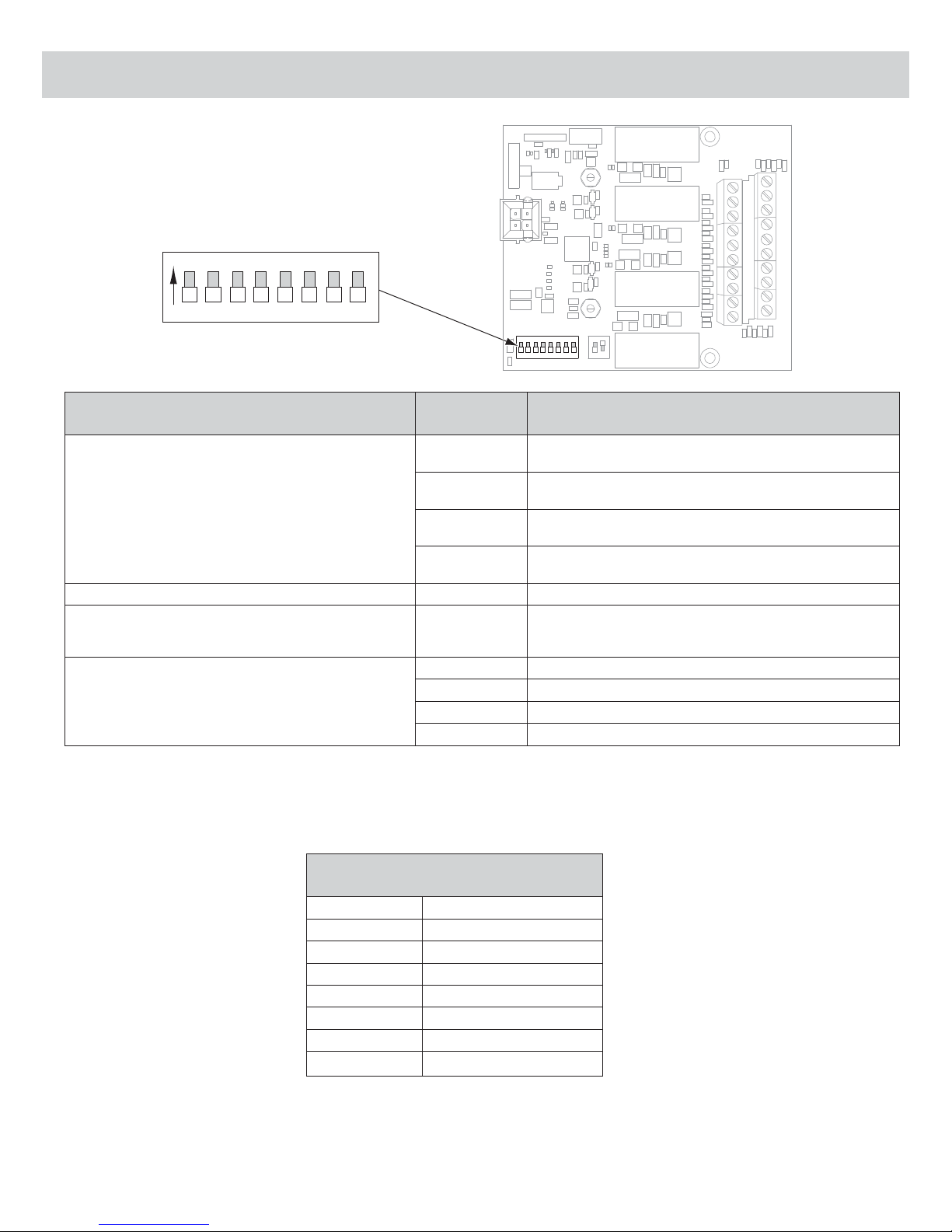
Board Input Power Board requires 0.1A max. of power supply output current to operate
Temperature Range 32°-120° F (0°- 49° C)
Compliance UL 294, ULC-S318, RoHS, & FCC Part 15
Fire Alarm Input Accepts 900-FA Fire Alarm Board (Optional)
900-2RS Specifications:
900-BB Battery Backup
(optional)
Page 3
900-2RS (optional) - Page 4
(2 Zone EL Control -
Individual/Sequential)
900-KL Keylock
(optional)
Page 2
PS914 Power Supply
Pages 1-3
F1
DANGER
!
!
DANGER:
!
WARNING:
!
WARNING: