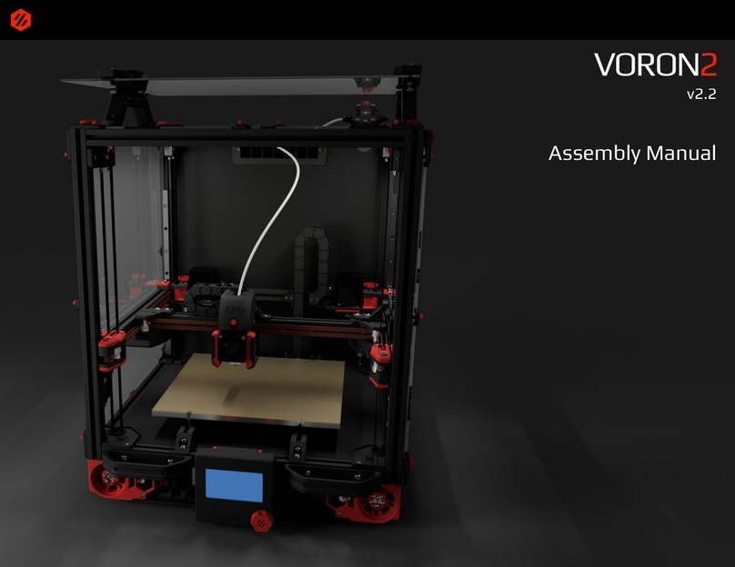
VORON ERCF v2 User manual

We build space shuttles with gardening tools
so anyone can have a space shuttle of their own.
VERSION 2023-11-21
ERCF v2 BUILD GUIDE
COMMUNITY EDITION

WWW.VORONDESIGN.COM
CAD version: ERCF V2
2
Before you begin on your journey, a word of caution.
This machine can maim, burn, and electrocute you if you are not careful.
Please do not become the first VORON fatality.
There is no special Reddit flair for that.
Please, read the entire manual before you start assembly.
As you begin wrenching, please check our Discord channels for
any tips and questions that may halt your progress.
Most of all, good luck!
The VORON Team
2
ERCF v2

WWW.VORONDESIGN.COM
CAD version: ERCF V2
33
ERCF v2
Introduction 10
Wiring 18
Gearbox 24
Filament Blocks 52
End Block 71
Selector 79
Encoder 94
Linear Axis 103
Final Assembly 113
CottonTail Buffer 127
TABLE OF CONTENTS

WWW.VORONDESIGN.COM
CAD version: ERCF V2
4
PART PRINTING GUIDELINES
The Voron Team has provided the following print guidelines for you to follow in order to have the best chance at success with
your parts. There are often questions about substituting materials or changing printing standards, but we recommend you
follow these.
4
INTRODUCTION
FDM MATERIAL
The ERCF was tested only with ABS, so I
recommend to use ABS to build the ERCF.
INFILL TYPE
Grid, Gyroid, Honeycomb, Triangle or Cubic.
MATERIAL
The ERCF was tested only with ABS, so I
recommend to use ABS to build th
INFILL PERCENTAGE
Recommended: 40%
LAYER HEIGHT
Recommended : 0.2mm
WALL COUNT
Recommended : 4
EXTRUSION WIDTH
Recommended : Forced 0.4mm
SOLID TOP/BOTTOM LAYERS
Recommended : 5
Beware that this project requires a well tuned printer and slicing profile, as there are many press fits and plastic on plastic
mechanisms. You should first print the ERCF_Calibration_Tool.stl, test the part, as shown in the manual, tune your printer and
profile if needed, and then only print the rest of the parts.
PRINT GUIDELINES

WWW.VORONDESIGN.COM
CAD version: ERCF V2
5
FILE NAMING
By this time you should have already downloaded our STL files from the Voron GitHub. You might have noticed that we have
used a unique naming convention for the files. This is how to use them.
5
PRIMARY COLOR
Example End_Bypass.stl
These files will have nothing at the
start of the filename.
ACCENT COLOR
Example [a]_End_Bypass_Foot.stl
These files have an ‘’[a]_’’ prefix to
denote that they should be printed
with an accent color.
QUANTITY REQUIRED
Example Filament_Path_xN.stl
Files ending with ‘’_x#’’ are telling
you the quantity of that part required
to build this system. For the ERCF,
‘’N’’ means the number of channels.
COLOR REQUIRED
Example
[c]_Cover_Lens_xN.stl
These files have a ‘’[c]’’prefix to
denote that they need to be printed in
a clear/transparent material.
COLOR REQUIRED
Example
[o]_Encoder_Slotted_Wheel.stl
These files have an ‘’[o]’’prefix to
denote that they need to be printed in
an opaque material light can’t
penetrate, preferably black.
OPTIONAL MULTIMATERIAL
Example
[mm]_Voron_Logo_Plate.stl †
These files have a ‘’[mm]’’prefix to
denote that they should be printed in
multiple colors. We always include
single-color versions of these files
too, for your first build.
INTRODUCTION STL FILE KEY

WWW.VORONDESIGN.COM
CAD version: ERCF V2
66
INTRODUCTION HARDWARE REFERENCE
BUTTON HEAD CAP SCREW (BHCS)
Metric fastener with a domed shape head
and hex drive. Most commonly found in
locations where M5 fasteners are used.
ISO 7380-1
SOCKET HEAD CAP SCREW (SHCS)
Metric fastener with a cylindrical head
and hex drive. The most common
fastener used on the ERCF.
ISO 4762
FLAT HEAD COUNTERSUNK SCREW
(FHCS)
Metric fastener with a cone shaped head
and a flat top.
ISO 10642
SELF TAPPING SCREW
Fastener with a pronounced thread
profile that is screwed directly into
plastic.
HEX NUT
Hex nuts couple with bolts to create a
tight, secure joint. You’ll see these used
in both M3 and M5 variants throughout
this guide.
ISO 4032
MAGNETS
How do they work?
These are cylinders 6mm in diameter
and 3 mm tall. Shorter ones are OK,
down to 2.7 mm. N52 are preferred, but
N35 can work.
POST INSTALL T-SLOT NUT (T-NUT)
Nut that can be inserted into the slot of
an aluminium 2020 profile.
Often also called “roll-in t-nut.”
HAMMERHEAD NUT
Nut that can be inserted into the slot of
an aluminium profile. Used exclusively
for panel mounting, all other
components use T-Slot nuts.

WWW.VORONDESIGN.COM
CAD version: ERCF V2
77
INTRODUCTION HARDWARE REFERENCE
625 BEARING
A ball bearing used on the Voron Z
drives.
WASHER
Metric fastener with a domed shape head
and hex drive. Most commonly found in
locations where M5 fasteners are used.
ISO 7380-1
PULLEY
GT2 pulley used on the motion
system of the Voron.
IDLER
GT2 idler used in the motion system of the
Voron.
SET SCREW
Small headless screw with an
internal drive. Used in pulleys and
other gears. Also called a grub
screw.
ISO 4026
HEAT SET INSERT
These are made of brass , threaded on the
inside and and has ridges on the outside.
Heat them up to approx 250C with a
soldering iron and push them into the plastic.
As the plastic cools, it solidifies around the
knurls and ridges on the insert for excellent
resistance to both torque and pull-out.
5.5MM BALL BEARING
A ball bearing used in the CottonTail
Buffer.
608 BEARING
A ball bearing used on the ERCT Buffer
(optional),

WWW.VORONDESIGN.COM
CAD version: ERCF V2
88
INTRODUCTION TOOLS
BALL-END DRIVER
Some parts of this design require the use of a
ball-end hex driver for assembly. We recommend
you get a 2.0mm, 2.5mm and 3mm one.
2.5MM HEX DRIVER
The 2.5mm hex driver will see a lot of use in this
build. A quality driver is strongly recommended.
Refer to the sourcing guide for suggestions.
ADDITIONAL TOOLS
We provide additional tool recommendations in
our sourcing guide. Visit https://vorondesign.com/
sourcing_guide and switch to the “Voron Tools”
tab at the bottom of the page.

WWW.VORONDESIGN.COM
CAD version: ERCF V2
99
INTRODUCTION TOOLS
SOLDERING IRON
We use this for setting heat-set inserts into parts.
Depending on your sensor choice, you might be
soldering some wires together.
ANGLE GRINDER/DREMEL
If you need to cut your 8mm smooth rods, nothing
less than an angle grinder is going to cut it,
literally. Leave your grandfather’s trusty hacksaw
in the toolbox: rods are usually hardened steel.
VISE
A vise is handy if you have to cut your 8mm rods.
A vise may also be helpful when press-fitting
bearings into the Selector.
WIRING CRIMPER
You’ll need this to wire up the sensor. Or maybe
there’s a turnkey solution out there you can buy,
check Discord. If you got this far without learning
how to crimp, we don’t judge.
CAD SOFTWARE
ERCF_v2/CAD/ERCF_V2.0.step
Software is a tool too! The CAD file for the
ERCFv2 was designed to be used along with this
manual as a supplement or reference, even if you
aren’t a CAD Pro. You can use the free edition of
Fusion360, or your choice of CAD program such
as TinkerCAD or FreeCAD.
SUPERGLUE
Yes, we consider this a tool. Superglue is useful as
a plastic safe threadlock, and magnet glue. Cheap,
single-use gel tubes are fine.
PULLEY TOOLS
ERCF_v2\Stls\Tools\Pulley_Tool_NEMA14.stl
ERCF_v2\Stls\Tools\Pulley_Tool_NEMA17.stl
These take the guesswork out of setting your
pulley heights. You will always need the NEMA17
version, but you only need the NEMA14 version if
you’re using the NEMA14 drive motor.
80T GEAR WHEEL GUIDE
ERCF_v2\Stls\Tools\80T_Cog_Guide.stl
This tool helps you align your printed 80T gear
when you are assembling it.
SLOTTED WHEEL PUSH TOOL
ERCF_v2\Stls\Tools\Slotted_Wheel_Push_Tool.stl
Helps you set the depth and align the Encoder
slotted wheel without damaging it.
FILAMENT BLOCK BEARING INSTALL TOOL
ERCF_v2\Stls\Tools\Bearing_Install_Tool.stl
This optional tool helps you install MR85ZZ
bearings into the Filament Blocks without
damaging the bearings.
PRINTED PART TRACKER SPREADSHEET
There is a helpful interactive Printed Part Tracker
for ERCFv2 here:
Printed Parts Tracker Google Sheet

WWW.VORONDESIGN.COM
CAD version: ERCF V2
10
This project aims to bring multi material capabilities to 3D printers using a single Direct Drive toolhead. While this project is
mainly designed to be used on VORON printers, it can also be used (or adapted) on any 3D printer that runs Klipper.
Find all the project information on the Github page : https://github.com/Enraged-Rabbit-Community/ERCF_v2
The project is composed of 5 different components, some of which are optional:
●Enraged Rabbit Carrot Feeder (ERCF). The Carrot Feeder is the main unit and allows use of a high number of different
filaments (tested up to 14 tools but test team) and feed them, one at a time, into the printer toolhead on an as-needed
basis.
●Enraged Rabbit Cottontail (ERCT) is a new integrated (but optional) filament buffer system to handle the filament when
it is ejected from ERCF on a tool change. It can handle up to 1.5m bowden tube lengths. This has been specifically
designed to minimize friction when setup in accordance with this manual which takes into account the natural filament
memory. It has options for LED gate indicators and entry sensors.
●Enraged Rabbit Filametrix (ERF): This filament cutter is an optional toolhead modification to cleanly cut the tip of the
ejected filament, so it can be loaded easily on next use. This option alleviates the frustrating job of tuning tip formation
through movement of the filament within the extruder, which often still results in strings of filament causing clogs.
●Toolhead Sensor: This is a set of modifications for popular extruders that provides filament detection capability within
the toolhead. Although optional, it is highly recommended, and makes filament change far more reliable and smooth.
●Happy Hare Firmware: This has become the go-to extension to Klipper for controlling various types of MMU. It is
optimized to support ERCF.
●(Future) Enraged Rabbit Pellet Purge (ERPP): Envisioned, but currently unavailable, this will alleviate the need for a
purge tower meaning more room for your prints. Stay tuned.
10
INTRODUCTION THE ENRAGED RABBIT PROJECT

WWW.VORONDESIGN.COM
CAD version: ERCF V2
11
This is the place to recognize the origins and evolution of this project. ERCF was originally envisioned and created by Ette and
the v1.1 release credits Tircown, the Voron Dev team (special mention to Dunar), Benoit, Dustin Speed, Kageurufu and the
HonHonHonBaguette people!
Over time and significant adoption the shortcomings of ERCF v1.1 design came to light, and that inspired a set of
modifications to address them: SturdyBunny, TripleDecky, Springy, Binky and other strange names appeared. It was then that
Moggieuk, the author of Happy Hare, rounded up these project authors and created the beginnings of the ERCF v2
community release. As the project developed, Kinematicdigit developed and contributed CottonTail, Sorted developed and
contributed Filametrix and we were joined by some awesome talent that polished, tested and documented to complete the
project.
Many hundreds of hours of volunteer effort have gone into this project and we hope it pays tribute to Ette’s wonderful original
design. The BMW of MMU’s!
●@moggieuk V0.1503 | V2.4088 (Happy Hare Dev & Chief whip)
●@gneu V2.5345 (Filament block and bling innovator)
●@sneakytreesnake V2.3804 (The project backbone!)
●@mneuhaus VT.483 (Binky Dev)
●@Miriax (Designer & Doc Demon)
●@kinematicdigit (Cottontail Dev & Doc Illustrator)
●@ningpj (Tester, Breaker & Doc's)
●@fizzy (King of CAD)
●@gsx8299 (Test Builder Extraordinaire)
●@sorted (Filametrix "don't get enraged" filament cutting system Dev)
●@kierantheman (Thumper Dev)
👏 👏 👏
11
INTRODUCTION ACKNOWLEDGEMENTS

WWW.VORONDESIGN.COM
CAD version: ERCF V2
12
If you need assistance with your build you can head over the VORON Discord group and post your questions in the
ercf_questions channel. It is the primary medium to help people with their ERCF build and tuning! You can also check the
Github page for the latest releases.
12
INTRODUCTION
https://discord.com/channels/46011
7602945990666/90974391547581
6458
https://github.com/Enraged-Rabbit-
Community/ERCF_v2
HOW TO GET HELP

WWW.VORONDESIGN.COM
CAD version: ERCF V2
13
Constructing and operating a multi-filament system can be a challenging endeavor, often more intricate than assembling the
3D printer itself. Approach this task patiently, addressing each issue methodically. Be aware that minor complications during
assembly can accumulate, potentially leading to greater challenges later. If you encounter any uncertainties or roadblocks,
feel free to seek guidance on Discord - remember, there are no foolish questions!
You might have heard about the frequent challenges associated with multi-filament systems. Indeed, they can be demanding.
However, the Enraged Rabbit Project aims to provide a system that is not only innovative and reliable but also user-friendly.
Despite these efforts, encountering some difficulties is not uncommon. In such instances, consult the available documentation
and guides, and don't hesitate to ask for help on Discord. Many common issues have likely been encountered and resolved
before, so assistance is readily available.
Enjoy the process of building as much as utilizing your Enraged Rabbit Carrot Feeder (ERCF)!
13
INTRODUCTION FINAL THOUGHTS

WWW.VORONDESIGN.COM
CAD version: ERCF V2
14
Use this test to ensure your printer and slicing profile are properly tuned, in order to have a pleasant ERCF assembly experience.
TESTS
Insert the different pieces of hardware in their dedicated slots: 6x3mm magnet, M5 nut, and 8mm rod. They should grip the
hardware so that they don’t fall out easily, but they should not be very difficult to insert or remove. Test the heat set insert
hole using a soldering iron and insert.
Use the Filament Path to check that 1.75mm filament slides through without friction. The Filament Axis should have some
light friction.
To check the Top_Hat, insert the arm of a Tophat into the slot. It should insert without much force. Once inserted, the Tophat
should be able to move up and down easily. To remove the Tophat, pull it up while rotating it.
14
INTRODUCTION
8mm Rod Insert 1.75mm Filament Path
1.75mm Filament Axis M3 Heat Set Insert
Tophat
M5 Nut
6x3mm Magnet
CALIBRATION TOOL
Calib_Test

WWW.VORONDESIGN.COM
CAD version: ERCF V2
15
This design relies heavily on heat set inserts. If you’ve never worked with heat set inserts before, watch this guide :
https://www.youtube.com/watch?v=cyof7fYFcuQ
Here is a list of all the pages of this manual where you need to add the heatset inserts into the 3D printed parts, so you can
do this step all at once for the whole assembly :
• Page 27
• Page 32
• Page 41
• Page 84
• Page 85
• Page 86
• Page 96
• Page 106
Optionally, for the ERCT / CottonTail Buffer:
• Page 133
• Page 139
15
INTRODUCTION HEAT SET INSERTS

WWW.VORONDESIGN.COM
CAD version: ERCF V2
16
We have provided the ERCFv2 CAD files (ERCFv2/CAD/ERCFv2.STEP and ERCFv2.F3D), so that you can follow along with
the instructions in a 3D view, if you like.
The CAD file is organized into folders based on the instructions in this manual. First hide all the parts, and then reveal the
parts up to the step you are on in this manual, and the CAD should match what you are building.
All of the non-printed parts are in each section’s Hardware folder.
16
INTRODUCTION USING THE CAD FILE

WWW.VORONDESIGN.COM
CAD version: ERCF V2
17
If you are upgrading from ERCFv1 or v1.1, you can re-use some of the printed parts. These parts will have a dagger † every
time we mention the file name, in case you want to re-use those parts. Here is a list:
17
INTRODUCTION UPGRADING FROM ERCFv1
ERCF_v2 / STLs / Gear_Box
[a]_Bearing_Spacer_x2.stl †
[a]_Knob.stl †
[a]_Logo_Plate.stl †
[a]_M4_80T_Wheel.stl †
[a]_Side_Latch_x2.stl †
[mm]_Voron_Logo_Plate.stl †
Motor_Arm_NEMA14.stl †
Motor_Arm_NEMA14_EASYBRD.stl †
Motor_Arm_NEMA17.stl †
Motor_Arm_NEMA17_EASYBRD.stl †
ERCF_v2 / STLs / Linear_Axis
[a]_Drag_Chain_Anchor_Bottom.stl †
[a]_Motor_Lock.stl †
ERCF_v2 / STLs / Selector
Belt_Tensioner.stl †
Drag_Chain_Anchor.stl †
ERCF_v2 / STLs / Supports / Adjustable_Mount
[a]_Screw_x3.stl †
Junction_Plate_Flat_x2.stl †
Junction_Plate_Gear_Box.stl †
ERCF_v2 / STLs / Supports / Adjustable_Mount / 2020
2020_Mount.stl †
2020_Mount_Mirrored.stl †
ERCF_v2 / STLs / Supports / Adjustable_Mount /
3030_(SW_with_panels)
3030_Flat_Mount.stl †
3030_Flat_Mount_Mirrored.stl †
ERCF_v2 / STLs / Supports / Adjustable_Mount /
3030_(SW_without_panels)
3030_Mount.stl †
3030_Mount_Mirrored.stl †
ERCF_v2 / STLs / Supports / Adjustable_Mount / Option
ERCF_Easy_Brd_Bracket_Mount.stl †
ERCF_v2 / STLs / Supports / V1_V2
[a]_Support_Feet_4mm_x4.stl †
[a]_Support_Feet_5mm_x4.stl †
ERCF_v2 / STLs / Tools
Pulley_Tool_NEMA14.stl †
Pulley_Tool_NEMA17.stl †

WWW.VORONDESIGN.COM
CAD version: ERCF V2
LOCAL MCU VS REMOTE MCU
When we say “local MCU” we mean a “buddy board” or other dedicated MCU that will
be mounted near the ERCF. Examples include the BTT MMB (preferred and shown in
this manual) and the EASY BRD. Skip to page 21 if you’re using a local MCU.
When we say “remote MCU” we mean the dedicated MCU(s) for your printer. It is
unusual to have enough spare motor, servo, and endstop ports to run an ERCF unless
you’re using a dual SKR board setup, but if that’s you, then you can save some money
on the buddy board by using this option.
PREPARING THE WIRES FOR REMOTE MCU
For an ease of installation, it is recommended to prepare the wiring before assembly.
There are two wire looms to do:
●One that goes from the connector plate to the selector motor
●One that goes from the connector plate to all the other components, namely the
endstop, the servo and the encoder
1818
WIRING (REMOTE MCU)
Molex Microfit 3 – 4 pins Free Ends
CONNECTION TO THE SELECTOR MOTOR
When using a remote MCU, it is recommended to
finish the selector motor connection later in the
assembly, for ease of assembly and to ensure the
crimps are done with the proper wire length
SELECTOR MOTOR WIRE FOR REMOTE MCU
Prepare the 4 wire selector motor cable as shown. Don’t crimp the free ends for now.
SELECTOR MOTOR WIRE
Channels Selector Motor Wire Length (mm)
N175 + 25N
4275
5300
6325
7350
8375
9400
10 425
11 450
12 475
13 500
14 525
15 550
Wire Length Chart for remote MCU
All wire lengths in this manual
include approximately 25-50mm of
spare length for maintenance.

WWW.VORONDESIGN.COM
CAD version: ERCF V2
WIRING THE GEAR MOTOR WIRE
Double-check. You’re supposed to skip this page if you’re using a local MCU (“buddy board” like EASY BRD or BTT MMB). You
wouldn’t want to cut your wires too short!
Trim your Gear Motor wires to 85mm, then crimp and add the 4-pin Molex Microfit connector. That’s it!
1919
WIRING (REMOTE MCU)
Molex Microfit 3 – 4 pins
GEAR MOTOR WIRE
Gear Motor
85mm

WWW.VORONDESIGN.COM
CAD version: ERCF V2
20
5 WIRE BUS
Prepare the 5 wire bus for the ERCF as shown. The GND is shared between the Servo, the Encoder and the Endstop. The +5V
is shared between the Servo and the Encoder.
To join the multiple GND//+5V lines, either crimp them together or make a splice prior to the crimp position.
Only the Endstop is directly connected to this wire bundle, typically by soldering the wires directly on the microswitch pins.
It is recommended to finish the Servo and Encoder connections later in the assembly, for ease of assembly and to ensure the
crimps are done with the proper wire length.
This should be a 6-wire bus with a wire to control the Apron LEDs, but we added them late in development for RC1 release!
20
WIRING (REMOTE MCU)
Free Ends
Molex Microfit 3 – 5 pins
Servo Encoder Endstop
SENSOR AND ENCODER WIRE BUS
Channels
Wire Length (mm)
Endstop Servo Encoder
N60 35 + 5N 45 + 5N
460 55 65
560 60 70
660 65 75
760 70 80
860 75 85
960 80 90
10 60 85 95
11 60 90 100
12 60 95 105
13 60 100 110
14 60 105 115
15 60 110 120
Table of contents
Other VORON 3D Printer manuals