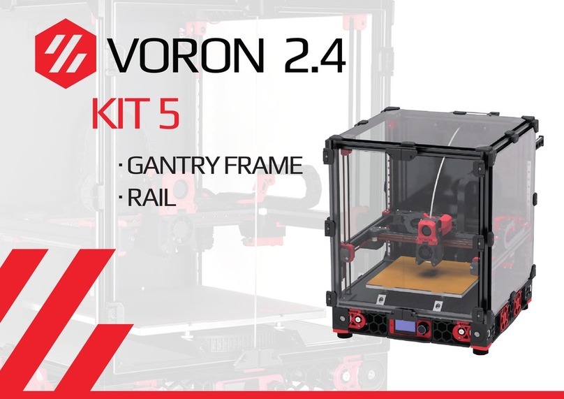
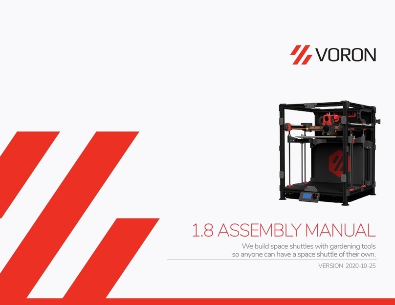
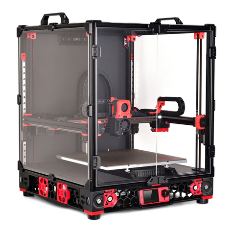
VORON 2.4 User manual

1
VORONDESIGN.COM
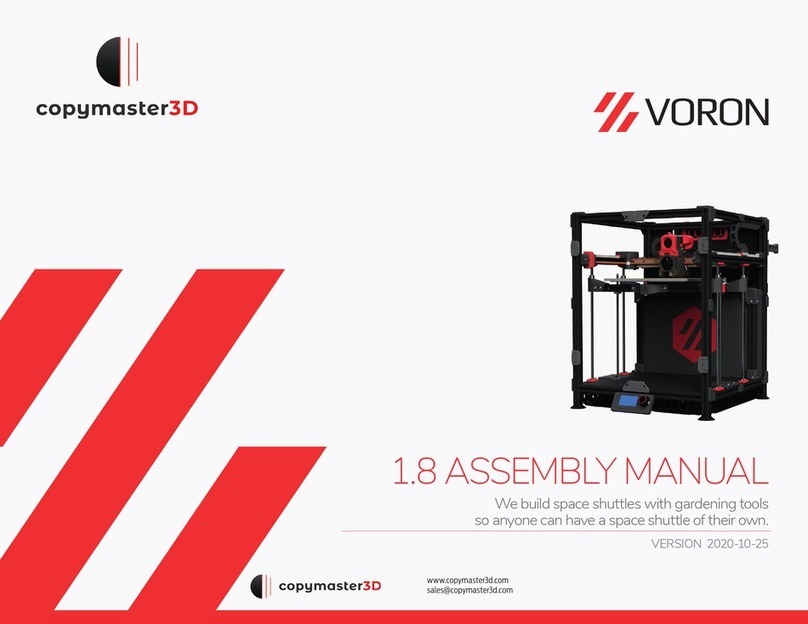
VERSION 2020.12.09
2.4 ASSEMBLY MANUAL
We build space shuttles with gardening tools
so anyone can have a space shuttle of their own
VORON

2
VORONDESIGN.COM
VORON 2.4 TABLE OF CONTENTS
Introduction
Frame Assembly
Z Drive
Build Plate
AB Drive Modules
Gantry
Afterburner
Belting Z Drive
03
10
18
30
38
46
58
78
LCD Module
Skirts
Panels
Spool Holder
Exhaust Filter
Electronics Mounting
Wiring
Pre-Flight Checklist
82
86
94
102
106
112
118
129

3
VORONDESIGN.COM
INTRODUCTION
Before you begin on your journey, a word of caution.
In the comfort of your own home you are about to assemble a robot. This
machine can maim, burn, and electrocute you if you are not careful. Please
do not become the rst VORON fatality. There is no special Reddit air for that.
Please, read the entire manual before you start assembly. As you begin wrenching,
please check our Discord channels for any tips and questions that may halt your progress.
Most of all, good luck!
The VORON Team

4
VORONDESIGN.COM
By this time you should have already downloaded our STL les from the Voron GitHub. You might
have noticed that we have used a unique naming convention for the les. This is how to use them.
INTRODUCTION STL FILE KEY
PRIMARY COLOR
Example z_joint_lower_x4.stl
These les will have nothing at the
start of the lename.
ACCENT COLOR
Example [a]_tensioner_left.stl
We have added “[a]” to the front of any
STL le that is intended to be printed
with accent color.
QUANTITY REQUIRED
Example [a]_z_belt_clip_lower_x4.stl
If any le ends with “_x#”, that is telling
you the quantity of that part required to
build the machine.
STL OPTIONS
You have some options on the STL’s you print for your Voron.
DIN BRACKETS or LEGACY
VORON2.4\Electronics_Compartment
DIN brackets are used for the current
printer specication. Use this if you’re
doing a new build.
Legacy brackets are used to mount
electronics to the frame if you are not
using DIN rail.
DIRECT FEED or BOWDEN
VORON2.4\Gantry\X_Axis\X Carriage
Direct feed is the standard setup for
most new builds.
Bowden allows for an external extruder
to be used. If in doubt, print the direct
feed.
CABLE CHAIN or ZIP CHAIN
VORON2.4\ZipChain
We recommend using cable chain. You
can check the sourcing guide for options.
If you prefer to print zip chain, you can
nd it in the folder listed above.

5
VORONDESIGN.COM
INTRODUCTION PRINT GUIDELINES
PRINT IT FORWARD
Often times our community members have issues printing ABS will bootstrap themselves into a VORON using our Print It Forward
program. This is a service where approved members with VORON printers can make you a functional set of parts to get your own machine
up and running. Check Discord if you have any interest in having someone help you out.
The Voron Team has provided the following print guidelines for you to follow in order to have the best chance at success with your
parts. There are often questions about substituting materials or changing printing standards, but we recommend you follow these
recommendations as closely as possible.
FDM MATERIAL
VORON printers are ABS capable machines that
run at impressive print speeds. For that reason we
recommend only using ABS to build your printer.
LAYER HEIGHT
Recommended: 0.2mm
EXTRUSION WIDTH
Recommended: Forced 0.4mm
INFILL PERCENTAGE
Recommended: 40%
INFILL TYPE
Grid, Gyroid, Honeycomb, Triangle or Cubic
WALL COUNT
Recommended: 4
SOLID TOP/BOTTOM LAYERS
Recommended: 5
SUPPORTS REQUIRED
None at all.

6
VORONDESIGN.COM
INTRODUCTION HOW TO GET HELP
If you need assistance with your build, we’re here to help. Head on over to our Discord group
and post your questions. This is our primary medium to help VORON Users and we have a great
community that can help you out if you get stuck.
THIS IS JUST A REFERENCE
This manual is designed to be a simple reference manual. Building a Voron can be a complex endeavour
and for that reason we recommend downloading the CAD les off our Github repository if there are
sections you need clarication on. It can be sometimes be easier to follow along when you have the whole
assembly in front of you.
https://github.com/vorondesign
https://discord.gg/xgXWctB

7
VORONDESIGN.COM
INTRODUCTION FINAL THOUGHTS
VORON printers are amazing machines that take care and attention to assemble. Take your time! Little issues in the assembly phase tend to
stack up and cause you trouble later on. If at any point you get stuck or are just not sure about something, please ask on Discord. There are
no stupid questions and we’re more than happy to point you in the right direction.
MAINS POWER
VORON printer builds require 110v/220v wiring work. It’s important to understand what you’re doing to
avoid injury or death. Mains power can kill, and it will hurt the entire time you’re dying from it. If in doubt we
encourage you to ask questions. This is not something you want to guess your way through.
PRINTED PARTS
Not all prints come off the printer perfect and may require some nishing work. You may nd that you need
to do some light sanding to get some parts to sit ush with each other. Take your time to get the tment
right.
Best of luck on your build! The VORON Team looks forward to seeing your serial application soon!

8
VORONDESIGN.COM
HARDWARE
BUTTON HEAD CAP SCREW (BHCS)
Metric fastener with a domed shape head
and hex drive. Most commonly found in
locations where M5 fasteners are used.
SOCKET HEAD CAP SCREW (SHCS)
Metric fastener with a cylindrical head
and hex drive. The Most common fastener
used on the Voron.
HEX NUT
Hex nuts couple with bolts to create a
tight, secure joint. You’ll see these used in
both M3 and M5 variants throughout this
guide.
SHIM
Not to be confused with stamped
washers. These are used in all M5 callout
locations in this manual.
HEAT SET INSERT
Heat inserts with a soldering tip so that
they melt the plastic when installed.
As the plastic cools, it solidies around
the knurls and ridges on the insert for
excellent resistance to both torque and
pull-out.
IDLER
GT2 idler used in the motion system of
the Voron. Used in two sizes for both
6mm and 9mm belt locations.
PULLEY
GT2 pulley used on the motion system of
the Voron. Used in two sizes for both 6mm
and 9mm belt locations.
ISO 7380-1
ISO 4762
ISO 4032
DIN 988

9
VORONDESIGN.COM
HARDWARE CONT.
625 BEARING
A ball bearing used on the Voron Z drives.
F695 BEARING
A thinner ball bearing with a ange used in
various gantry locations.
GRUB SCREW
Used to secure pulleys to stepper motor
drive shafts. Take care to tighten these
correctly and secure with thread lock
compound.

10
VORONDESIGN.COM
FRAME

11
VORONDESIGN.COM
GATHERING EXTRUSIONS
GETTING EXTRUSIONS TOGETHER
Separate the extrusions you’re going to need
for this section of the build. We’ve laid out all
the parts you should have and highlighted
the ones that will be used in the following
sections.

12
VORONDESIGN.COM
ASSEMBLE FIRST CORNER
M5X16 BHCS
Use a low strength thread lock
compound here.

13
VORONDESIGN.COM
ATTACHING MIRROR SIDE
BUILDING SQUARE
It’ not a bad idea to build this frame on a glass surface
to ensure you can get it as square as possible.

14
VORONDESIGN.COM
ASSEMBLE FRAME TOP
CHECK THE FRAME
Use a framing square and ensure all corners are
as square as possible before moving on or you may
have problems later on when you start printing.

15
VORONDESIGN.COM
BED EXTRUSIONS
M5X10 BHCS M5 Shim
FASTENERS
Insert fasteners before you start. It makes attaching the
bed extrusions to the frame easier. Don’t tighten these
down too hard at this stage. We’ll want them loose when
we install the heated bed assembly!
M5X16 BHCS

16
VORONDESIGN.COM
Z AXIS LINEAR RAILS
M3X8 SHCS
DON’T OVER TIGHTEN!
The M3 fasteners that hold the linear rails to the
frame do not need to be hulked down. Tighten
them sufciently to hold to the extrusion
without over tightening them.
CENTERED RAIL INSTALLATION GUIDE
When tightening the fasteners to hold the linear
rails in place, ensure that you have attached a
centered rail installation guide to both the top
and bottom. You should have two printed.
RAIL SPACING
Make sure to space the rails 3mm off the bottom
extrusions. This leaves room for the installation
of belt covers later in the build.

17
VORONDESIGN.COM
This page intentionally left blank.

18
VORONDESIGN.COM
Z DRIVE ASSEMBLY

19
VORONDESIGN.COM
Z BELT DRIVE & STEPPER
GT2 16T Pulley
INSTALL HEAT SET INSERTS
You will need to install heat set inserts into all
four sets of Z drive housings. If you need help on
the correct procedure, ask in Discord.
APPLY THREAD LOCK COMPOUND
Make sure to apply thread lock compound
to the grub screws.

20
VORONDESIGN.COM
BELT DRIVE SHAFT ASSEMBLY
625 Bearing
GT2 80T Pulley
GT2 20T 9MM Pulley
625 Bearing
APPLY THREAD LOCK COMPOUND
Make sure to apply thread lock compound
not only to the 9mm pulley grub screws,
but also the 80T pulley!
625 Bearing
M5 Shim
Other manuals for 2.4
2
Table of contents
Other VORON 3D Printer manuals