Vorsprung Smashpot User manual

Installation Instructions
REV C
1

There are 3 main sections to installing the Smashpot
1. Removing the stock air spring assembly from your fork
2. Configuring the Smashpot to your travel and spring rate
3. Installing the Smashpot assembly into your fork
Note: Do not proceed unless you have the following tools and supplies on hand:
TOOLS REQUIRED:
Torque wrench
Torque wrench to spanner adaptor
12mm Spanner
13mm Spanner (29er PIKE only)
14mm Cone Wrench
22mm Cone Wrench
12mm Socket
28mm Chamferless Socket
2mm + 1.5mm Allen Keys
Oil syringe or graduated cylinder
Sharp knife or scissors
SUPPLIES REQUIRED
Slick Honey Grease or alternative
110ml of 20wt fork oil
PART 1: REMOVE STOCK AIR SPRING
See manufacturers service instructions for disassembling the stock air spring and removing it
completely from your fork. The Vorsprung Smashpot kit will replace the entire stock air spring
assembly including foot stud and top cap and this must be removed first.
Refer to the relevant factory service instructions up until you have removed the air spring from
the stanchion. Unless your fork requires additional servicing, the damper and seals will not need
to be touched to install the Smashpot.
FOX: https://www.ridefox.com/fox17/help.php?m=bike&listall=service
ROCKSHOX: https://www.sram.com/service/rockshox/7,434
Refer to the Factory service instructions for torque specifications, lubrication specifications and
general disassembly/reassembly.
2

KIT CONTENTS
Figure 1: Kit Contents
3

PARTS LIST AND SECTION VIEW
Drawing 1: Isometric view of Smashpot assembly
PART 2: CONFIGURE SMASHPOT
Your kit will consist of a number of items as per the above parts list. Depending on the travel of
your fork you will have to configure the top out and main spring spacers accordingly.
In some cases the travel of your fork may be increased, however, it is your responsibility
to check with the fork manufacturer to ensure this is permissible. Bushing overlap and
damper length may restrict this and improperly installed products can fail, causing the rider to
lose control resulting in SERIOUS INJURY OR DEATH. Check the maximum allowable travel of
your fork with the fork manufacturer prior to increasing travel above your factory-set travel.
4

5

SMASHPOT ASSEMBLY
1. Remove TOPCAP and SPRING COLLAR
from the INNER TUBE ASSEMBLY in order
to remove the SEAL HEAD and access the
TOP OUT SPRING SPACERS. Part
Number: 13-07-2-08
2. Install a stack height of TOP OUT
SPRING SPACERS as required to suit your
fork travel. TOP OUT SPRING SPACERS
must sit on the INNER TUBE between TOP
OUT SPRING ASSEMBLY and
SEALHEAD. See Drawing 2 and table
below for details. For example: a 160mm
travel fork requires 20mm of TOP OUT
SPRING SPACERS so install 2 x 10mm
spacers.
TOP OUT SPRING SPACERS
Fork Travel
(mm)
Spacer Stack Height
(mm)
130
50
140
40
150
30
160
20
170
10
180
NONE
3. Re-install the SEAL HEAD onto the
INNER TUBE ASSEMBLY and insert the
INNER TUBE ASSEMBLY into the OUTER
TUBE ASSEMBLY.
6

4. Using a 14mm cone wrench on the SEAL
HEAD and a 22mm cone wrench on the
BOTTOM OUT CUP - use a Torque wrench
to torque SEAL HEAD to 75in.lbs without
loctite.
5. Position and install the included length of
HEAT SHRINK just shy of the ports and
extending over the end of the SEAL HEAD
using a heat gun. **Make sure you do not
cover the ports with Heat Shrink
6. Push INNER TUBE into the OUTER
TUBE assembly as far as possible. Using a
sharp knife or scissors, trim back the Heat
Shrink to be in line with the end of the Seal
Head. (Try not to score the shaft with the
knife but note that scratches are not critical -
it is not a sealing surface.)
7. Install a stack height of MAIN SPRING
SPACERS on the outer tube as required to
suit your fork travel. See Drawing 2 above
7

and following table for details. For example:
a 160mm travel fork requires 30mm of
MAIN SPRING SPACERS so install 1 x
20mm spacer + 1 x 10mm spacer.
MAIN SPRING SPACERS
Fork Travel
(mm)
Spacer Stack Height
(mm)
130
NONE
140
10
150
20
160
30
170
40
180
50
8. Place the acetal SPRING PERCH into
the end of the COIL SPRING. It may fit one
end of the spring better than the other. The
better fitting end will be the top of the spring
as oriented in the fork.
9. Slide the Heat Shrink provided on to the
COIL SPRING , approximately 100mm from
the top end of the spring where the SPRING
PERCH will be fitted.
10. Use a heat gun to heat the Heat Shrink
until it fits snugly over the COIL SPRING.
Once shrunk, trim any excess from the ends
of the Heat Shrink that protrudes inside the
inner diameter of the COIL SPRING. When
complete, check that the spring slides
smoothly over the cartridge OUTER TUBE.
8

11. Install the COIL SPRING, SPRING
PERCH and SPRING COLLAR onto the
assembly. Ensure the SPRING PERCH is
positioned between the COIL SPRING and
the SPRING COLLAR. Correct preload
needs to be set such that the SPRING
COLLAR is tightened 1-4mm beyond the
point at which the COIL SPRING is first
contacted by the SPRING PERCH and has
no play along the length of the cartridge
tube.
Preload needs to be adjusted using the
included spacers so that the spring is
properly secured when approximately 9mm
of INNER TUBE thread is exposed (min
8mm, max 10mm). Too little preload may
result in the spring moving around and
causing noise - too much may result in
topout noise. If you are experiencing
substantial topout noise even with minimum
preload, please contact us.
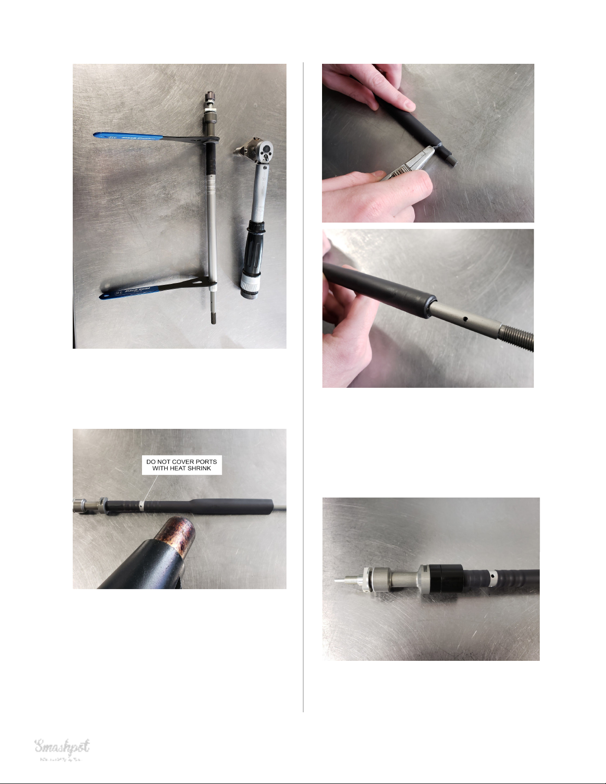
Insert a 2mm allen key through the hole in
the INNER TUBE to prevent it from rotating
if required.
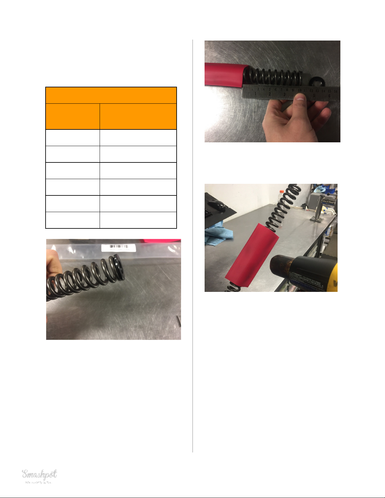
12. Check that the COIL SPRING is
adequately pre-loaded so that it is not able
to rattle around. One or two of the 2mm
SPRING SPACERS (part number:
13-07-3-08) may be required for appropriate
preload. Position the longest spacers
closest to the COIL SPRING and the
shortest spacers furthest away as this help
stabilise the spring assembly during use.
**NOTE: Getting preload right is necessary
for proper operation of the fork. Too much
or too little can cause substantial noise.
ADDITIONAL STEPS (13 & 14)
FOR PIKE 29er FORKS ONLY
13. All PIKE kits include a 20 mm long
TOPCAP ADAPTOR to be used when
installing the kit in a 29in fork. 27.5in PIKES
do not require this adaptor. All other kits
do not include or require this adaptor either.
9

14. Thread the TOP CAP ADAPTOR into
the TOPCAP. Use a Torque wrench, 28mm
chamferless socket and 13mm Spanner to
torque to 45in.lbs without loctite.
15. Thread the TOPCAP onto the INNER
SHAFT ASSEMBLY
16. Use a Torque wrench + 28mm
chamferless socket on the TOPCAP and a
12mm Spanner on the SPRING COLLAR to
torque to 45in.lbs without loctite. DO NOT
EXCEED TORQUE SPECIFICATION.
**It is important that the SPRING COLLAR
be tightened against the TOPCAP. Do not
simply tighten the TOPCAP onto the INNER
SHAFT until the threads bottom out. This
will damage the assembly.
17. If the ADJUSTER DIAL and footnut are
installed already on your FOOT STUD, use
a 1.5mm allen key to unscrew the set screw
in the ADJUSTER DIAL until it slides easily
off.
18. Unscrew the FOOTNUT by hand and
remove it and the CRUSH WASHER from
the assembly.
10

11

ADDITIONAL STEP (19)
FOR FOX 36 FORKS ONLY
19. Using a Heat Gun, install additional
50mm length of red Heat Shrink over the
top of existing Heat Shrink on the COIL
SPRING. This step helps prevent noise
from spring deflection due to the larger
diameter stanchion on the Fox 36. NOTE:
NOT NECESSARY ON 36 RHYTHM.
20. The complete Smashpot assembly is
now ready to be inserted into your fork and
should look like the picture above.
PART 4: SMASHPOT INSTALLATION
21. Apply a generous amount of Slick
Honey grease to the COIL SPRING
especially the portion covered in Heat
Shrink. Insert assembly into the fork as
shown. Be careful as the needle adjuster is
small diameter and could be damaged if the
assembly is dropped into the fork lower.
22. Install CRUSH WASHER and
FOOTNUT onto the FOOTSTUD.
12

23. Use a Torque wrench and 12mm socket
to torque the FOOTNUT to 55in.lbs without
loctite.
24. Apply a fresh drop of blue 243 loctite to
the set screw and torque to 8in.lbs using a
1.5mm Allen key. Ensure the set screw is
aligned so that it contacts the flat portion of
the adjuster shaft.
25. Using a syringe or graduated cylinder
add 20wt suspension fluid as per the
following table.
REQUIRED OIL QTY
Fork
20wt Suspension Fluid
(mL)
PIKE
100
LYRIK
110
FOX 36
110
Note: Rockshox 0W30 oil is an acceptable
substitute. A lighter fork oil (10wt or 5wt)
may be substituted for cold weather riding
(below freezing temperatures).
26. Use a Torque wrench and 28mm
chamferless socket to torque the TOPCAP
to 220in.lbs (for FOX) 250in.lbs (for
ROCKSHOX) without loctite.
Installation is complete.
Now go ride your bike!
13

SMASHPOT TUNING
The Smashpot utilises a hydraulic damping system that engages during the last third of the fork
travel in order to prevent harsh bottom out of the suspension. The amount of damping force can
be adjusted by modifying the adjuster dial position or by modifying the shim stack. Given you
are running the correct spring rate for your weight and riding style, the adjustment range
provided by using the adjuster dial should be adequate for the majority of riders.
1. Adjuster Dial
To increase (+) bottom out stroke compression damping (firmer), turn the Smashpot
adjuster dial clockwise.
To decrease (-) bottom out stroke compression damping (softer), turn the Smashpot
adjuster dial counter-clockwise.
14

2. Shim Stack
If you cannot obtain the desired level of bottom out resistance by modifying the position of the
adjuster dial, there is also a speed sensitive shim stack that can be reconfigured to increase or
decrease the damping force.
If you have wound the adjuster dial all the way out (anti-clockwise) and find there is still too
much bottom out resistance. Or if you have wound the adjuster dial all the way in (clockwise)
and find there is still not enough bottom out resistance - follow the below procedure:
SHIM STACK MODIFICATION
1. Remove Smashpot assembly from your
fork by working backwards through the
installation instructions.
2. Use a 22mm Cone Wrench on the
BOTTOM OUT CONE and a 12mm
Spanner on the FOOTSTUD to remove the
FOOTSTUD and shim stack assembly from
the rest of the OUTER TUBE ASSEMBLY.
3. Once removed, shims can be
repositioned to increase of decrease the
bottom out resistance. See Drawing 3
below.
To decrease bottom out resistance -
reposition one of the MAIN SHIMS to be
located in between the SPACER SHIM and
the CLAMP SHIM.
To increase bottom out resistance - add an
additional MAIN SHIM to the existing stack
of 5 MAIN SHIMS. 9mm ID x 16mm OD x
0.2mm thick
15

4. Reinstall the FOOTSTUD and modified
shim stack into the OUTER TUBE
ASSEMBLY.
Using a 12mm spanner on the FOOTSTUD
and a 22mm Cone Wrench on the BOTTOM
OUT CONE Torque to 75in.lbs without
loctite.
Drawing 3: Stock shim stack configuration
CHANGING COIL SPRINGS
The correct spring for your weight and riding style should have been selected at the time of
purchase. If you are running too much or too little sag and need to remove and replace the
spring, this can be done by following the below procedure. Note: having a new, clean gear shift
cable on hand will make this a much easier process.
16

REMOVE & REPLACE COIL SPRING
1. Remove TOPCAP using 28mm
chamferless socket.
2. Use a 28mm chamferless socket on the
TOPCAP and a 12mm Spanner on the
SPRING COLLAR to remove the TOPCAP
3. Remove SPRING COLLAR, SPRING
PERCH and COIL SPRING. The INNER
TUBE will fall down inside the stanchion.
Compress the fork fully and you should be
able to grab the INNER TUBE and pull it out
of the stanchion.
4. Thread a gear shift cable through the
hole in the top of the INNER TUBE and
through the new COIL SPRING. The COIL
SPRING should be orientated with the
HEAT SHRINK closest to the top.
5. Use the shift cable to pull the INNER
TUBE up through the COIL SPRING until
the threads of the INNER TUBE are
exposed above the COIL SPRING.
17

6. Install the SPRING PERCH and SPRING
COLLAR onto the INNER TUBE and tighten
down until 8-10mm of threads are exposed.
7. Thread the TOPCAP onto the INNER
SHAFT ASSEMBLY
8. Use a Torque wrench + 28mm
chamferless socket on the TOPCAP and a
12mm Spanner on the SPRING COLLAR to
torque to 45in.lbs without loctite. DO NOT
EXCEED TORQUE SPECIFICATION.
**It is important that the SPRING COLLAR
be tightened against the TOPCAP. Do not
simply tighten the TOPCAP onto the INNER
SHAFT until the threads bottom out. This
will damage the assembly.
22. Use a Torque wrench and 28mm
chamferless socket to torque the TOPCAP
to 220in.lbs (for FOX) 250in.lbs (for
ROCKSHOX) without loctite.
For more information, visit vorsprungsuspension.com
18
Table of contents
Popular Other manuals by other brands

AEMC
AEMC Simple Logger II series quick start guide

Airaid
Airaid 300-143 Installation instructions manual

Honeywell
Honeywell BFW112 Operating and maintenance manual

KSB
KSB Hya-Duo D FL Compact Installation & operating manual

Bacharach
Bacharach Model 105 supplementary guide

AutoAqua
AutoAqua QEye&QShooter QES-200 user guide