VorTek Pro-V M23 User manual

Model M22/M23 Instruction Manual Table of Contents
VorTek Series M22 and M23
Pro-V™Vortex Flow Meters
Instruction Manual
Document Number M-000-00001
M22/M23, V
Rev 06/08
8475 W I-25 Frontage Rd. Suite 300 Longmont, CO 80504
(303) 682-9999 (888) 386-7835 Fax (303) 682-4368
IM-M22/M23 0-1

Table of Contents Model M22/M23 Instruction Manual
http://www.VorTekinst.com
Customer Notice
Unless you have specifically ordered VorTek’s optional O2cleaning, this flow meter
may not be fit for oxygen service. VorTek Instruments, Inc., is not liable for any
damage or personal injury, whatsoever, resulting from the use of VorTek Instru-
ments standard mass flow meters for oxygen gas. You are responsible for cleaning
the mass flow meter to the degree required for your oxygen flow application.
© COPYRIGHT VORTEK INSTRUMENTS 1997
No part of this publication may be copied or distributed, transmitted, transcribed, stored in
a retrieval system, or translated into any human or computer language, in any form or by
any means, electronic, mechanical, manual, or otherwise, or disclosed to third parties
without the express written permission of VorTek Instruments. The information contained
in this manual is subject to change without notice.
TRADEMARKS
Pro-V™ is a trademark of VorTek Instruments, Inc. Other product and company names
listed in this manual are trademarks or trade names of their respective manufacturers.
0-2 IM-M22/M23

Model M22/M23 Instruction Manual Table of Contents
Table of Contents
Chapter 1 Introduction
Pro-V™Vortex Flow Meters................................................................ 1-1
Using this Manual .........................................................................1-1
Note and Safety Information.........................................................1-2
Receipt of System Components .................................................... 1-2
Technical Assistance.....................................................................1-2
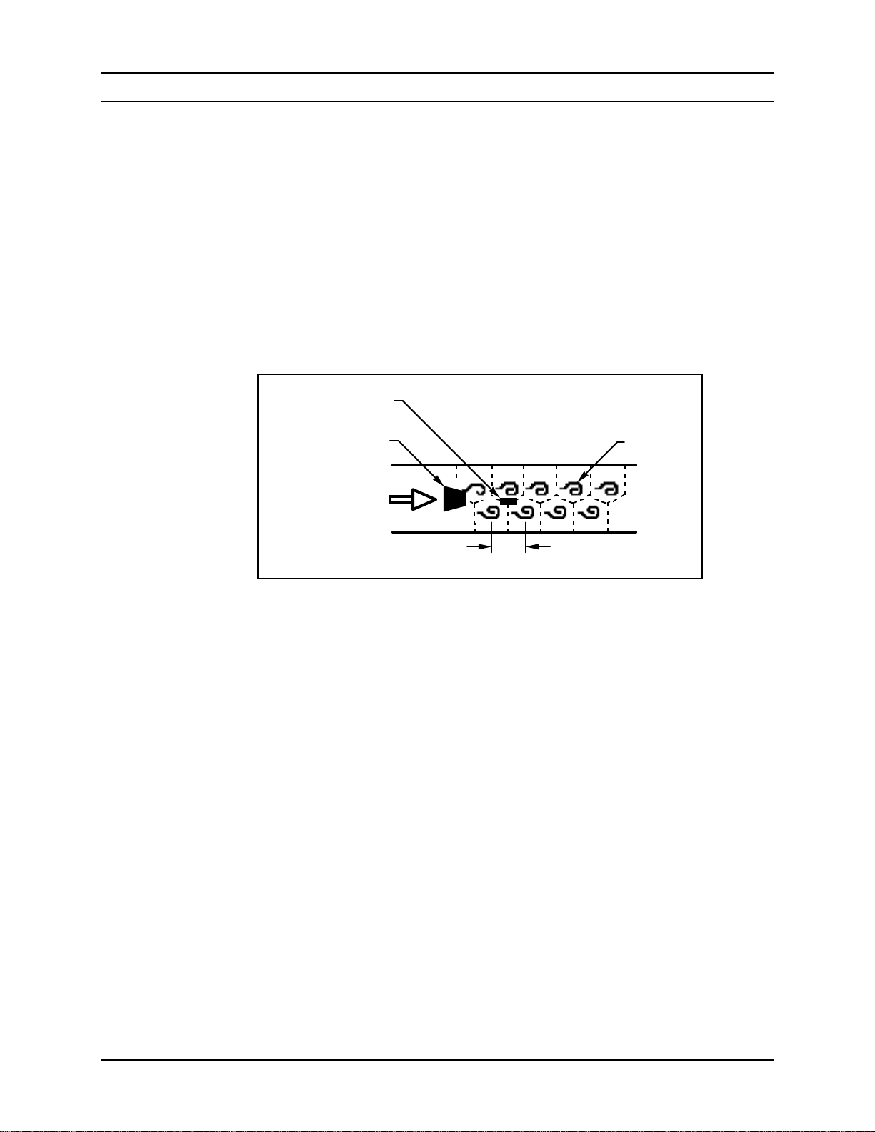
How the Pro-V Vortex Flow Meter Operates......................................1-3
Velocity Measurement/Pressure Drop........................................... 1-3
Flow Meter Configurations..................................................................1-7
Chapter 2 Installation
Installation Overview...........................................................................2-1
Flow Meter Installation Requirements..........................................2-1
Unobstructed Flow Requirements.................................................2-2
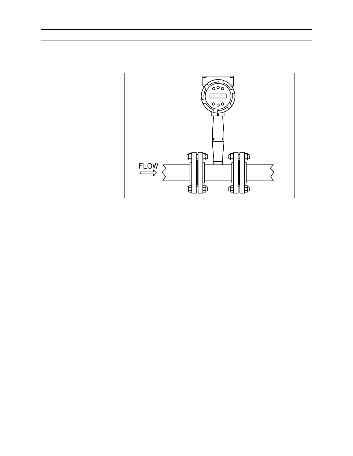
Model M22 In-Line Flow Meter Installation....................................... 2-3
Wafer-Style Flow Meter Installation............................................. 2-4
Flange-Style Flow Meter Installation............................................2-5
Model M23 Insertion Flow Meter Installation ....................................2-6
Cold Tap Guidelines......................................................................2-7
Hot Tap Guidelines .......................................................................2-8
Flow Meter Insertion ...........................................................................2-9
Installing Meters with a Compression Connection ..................... 2-10
Installing Meters with a Packing Gland Connection................... 2-12
Installing Meters (Packing Gland), No Insertion Tool................ 2-15
Adjusting Meter Orientation..............................................................2-17
Display/Keypad Adjustment ....................................................... 2-17
Enclosure Adjustment.................................................................2-18
Wiring Connections...........................................................................2-19
Input Power Connections............................................................2-19
Pulse Output Connections........................................................... 2-21
Remote Electronics Wiring.........................................................2-22
Chapter 3 Operating Instructions
Flow Meter Display/Keypad................................................................ 3-1
Start Up................................................................................................3-2
Using the Setup Menus........................................................................ 3-3
Programming the Flow Meter....................................................... 3-3
Output Menu .................................................................................3-4
Display Menu................................................................................3-5
Totalizer Menu.............................................................................. 3-6
Units Menu.................................................................................... 3-7
Diagnostics Menu..........................................................................3-8
Calibration Menu ..........................................................................3-9
Password Menu...........................................................................3-10
IM-M22/M23 0-3

Table of Contents Model M22/M23 Instruction Manual
Chapter 4 HART Communications
Wiring .................................................................................................4-1
HART Menus ......................................................................................4-2
Fast Key Sequence ..............................................................................4-3
Fast Key Sequence (continued) ..........................................................4-4
Chapter 5 Troubleshooting and Repair
Hidden Diagnostics Menus..................................................................5-1
Column One Hidden Diagnostics Values......................................5-2
Column Two Hidden Diagnostics Values.....................................5-3
Analog Output Calibration ..................................................................5-4
Troubleshooting the Flow Meter .........................................................5-4
Symptom: Output at no Flow........................................................5-4
Symptom: Erratic Output.............................................................. 5-4
Symptom: No Output....................................................................5-5
Electronics Assembly Replacement..................................................... 5-6
Returning Equipment to the Factory....................................................5-7
AppendixA Product Specifications
Appendix B Glossary
Appendix C ATEX-IECEX Specifications
0-4 IM-M22/M23

Model M22/M23 Instruction Manual Table of Contents
Warnings and Cautions
Warning!
Agency approval for hazardous location installations varies between flow meter models.
Consult the factory for specific flow meter approvals before any hazardous location instal-
lation. For explosion proof installations, you must use solid metal conduit and follow
NFPA (or your local code) approved wiring methods.
Hot tapping must be performed by a trained professional. U.S. regulations often require a
hot tap permit. The manufacturer of the hot tap equipment and/or the contractor perform-
ing the hot tap is responsible for providing proof of such a permit.
All flow meter connections, isolation valves and fittings for cold/hot tapping must have the
same or higher pressure rating as the main pipeline.
For Model M23 insertion flow meter installations, an insertion tool must be used for any
installation where a flow meter is inserted under pressure greater than 50 psig.
To avoid serious injury, DO NOT loosen a compression fitting under pressure.
All wiring procedures must be performed with the power Off.
Before attempting any flow meter repair, verify that the line is de-pressurized.
Always remove main power before disassembling any part of the mass flow meter.
Caution!
Calibration must be performed by qualified personnel. VorTek Instruments, Inc., strongly rec-
ommends that you return your flow meter to the factory for calibration.
In order to achieve accurate and repeatable performance, the flow meter must be in-
stalled with the specified minimum length of straight pipe upstream and downstream of
the flow meter’s sensor head.
When using toxic or corrosive gases, purge the line with inert gas for a minimum of four
hours at full gas flow before installing the flow meter.
Wafer-style flow meter gaskets must be carefully aligned to ensure accurate flow meas-
urement.
For Model M23 insertion flow meter installations, the sensor alignment pointer must point
downstream in the direction of flow.
IM-M22/M23 0-5

Table of Contents Model M22/M23 Instruction Manual
0-6 IM-M22/M23

Model M22/M23 Instruction Manual Chapter 1 Introduction
Chapter 1 Introduction
Pro-V™ Vortex Flow Meters
The VorTek Instruments’ Model M22 In-Line and the Model M23 Inser-
tion Pro-V™ Vortex Flow Meters provide a reliable solution for process
flow measurement. From a single entry point in the pipeline, Pro-V me-
ters offer precise measurements of mass or volumetric flow. The velocity
sensor reduces the effects of pipeline vibration by incorporating a unique
piezoelectric element that senses the vortex frequency. To extend range-
ability at the low end of flow, the meter’s smart electronics calculates the
Reynolds number (Re) based on constant values of fluid density and vis-
cosity stored in memory and automatically corrects for any non-linearity
down to Re = 5,000.
Pro-V digital electronics allows reconfiguration for most gases, liquids
and steam. The instrument is loop powered (12 to 36 VDC) with two
output signals. The pulse output signal is proportional to volumetric flow
rate; the analog linear 4-20 mA signal offers your choice of volumetric
flow rate or mass flow rate. The mass flow rate is based on a constant
value for fluid density stored in the instrument’s memory. The local key-
pad/display provides instantaneous flow rate in engineering units or to-
talized flow.
The VorTek Model M22 and M23 Pro-V Meters simple installation
combines with an easy-to-use interface that provides quick set up, long
term reliability and accurate flow measurement over a wide range of
flows and conditions.
Using This Manual
This manual provides the information needed to install and operate the
Model M22 In-Line and Model M23 Insertion Pro-V Vortex Flow Me-
ters. The four chapters of this manual cover these areas:
•Chapter 1 includes the introduction and product description
•Chapter 2 provides information needed for installation
•Chapter 3 describes system operation and programming
•Chapter 4 covers troubleshooting and repair
The product specifications are found in Appendix A. Appendix B con-
tains a glossary of terms.
IM-M22/M23 1-1

Chapter 1 Introduction Model M22/M23 Instruction Manual
Note and Safety Information
We use note, caution and warning statements throughout this book to
draw your attention to important information.
Warning!
Caution!
Note
This statement appears with
information that is important to
protect people and equipment
from damage. Pay very close
attention to all warnings that
apply to your application.
This statement appears with
information that is important
for protecting your equipment
and performance. Read and
follow all cautions that apply
to your application.
This statement appears with a
short message to alert you to
an important detail.
Receipt of System Components
When receiving a VorTek flow meter, carefully check the outside pack-
ing carton for damage incurred in shipment. If the carton is damaged, no-
tify the local carrier and submit a report to the factory or distributor. Re-
move the packing slip and check that all ordered components are present.
Make sure any spare parts or accessories are not discarded with the pack-
ing material. Do not return any equipment to the factory without first
contacting VorTek Customer Service.
Technical Assistance
If you encounter a problem with your flow meter, review the configura-
tion information for each step of the installation, operation and set up pro-
cedures. Verify that your settings and adjustments are consistent with fac-
tory recommendations. Refer to Chapter 4, Troubleshooting, for specific
information and recommendations.
If the problem persists after following the troubleshooting procedures
outlined in Chapter 4, contact VorTek Instruments, Technical Support at
(888) 386-7835 or (303) 682-9999 between 8:00 a.m. and 5:00 p.m.
MST. When calling Technical Support, have the following information
on hand:
•the flow range, serial number and VorTek order number (all
marked on the meter nameplate)
•the problem you are encountering and any corrective action
taken
•application information (gas, pressure, temperature and pip-
ing configuration)
1-2 IM-M22/M23

Model M22/M23 Instruction Manual Chapter 1 Introduction
How the Pro-V Vortex Flow Meter Operates
Figure 1-1. Model M22 In-Line Vortex Flow Meter
VorTek Model M22 and M23 Pro-V™Vortex Flow Meters use a unique
velocity sensor head to monitor volumetric flow rate. The built-in flow
computer calculates mass flow rate based on a constant value of fluid
density stored in the instrument’s memory. To measure fluid velocity,
the flow meter incorporates a bluff body (shedder bar) in the flow
stream, and the velocity sensor measures the frequency of vortices cre-
ated by the shedder bar. The velocity sensor head is located downstream
of the shedder bar within the flow body.
Velocity Measurement
The Pro-V vortex velocity sensor is a patented mechanical design that
minimizes the effects of pipeline vibration and pump noise, both of which
are common error sources in flow measurement with vortex flow meters.
The velocity measurement is based on the well-known Von Karman vor-
tex shedding phenomenon. Vortices are shed from a shedder bar, and the
vortex velocity sensor located downstream of the shedder bar senses the
passage of these vortices. This method of velocity measurement has many
advantages including inherent linearity, high turndown, reliability and
simplicity.
IM-M22/M23 1-3

Chapter 1 Introduction Model M22/M23 Instruction Manual
Vortex Shedding Frequency
Von Karman vortices form downstream of a shedder bar into two distinct
wakes. The vortices of one wake rotate clockwise while those of the
other wake rotate counterclockwise. Vortices generate one at a time, al-
ternating from the left side to the right side of the shedder bar. Vortices
interact with their surrounding space by over-powering every other
nearby swirl on the verge of development. Close to the shedder bar, the
distance (or wave length) between vortices is always constant and meas-
urable. Therefore, the volume encompassed by each vortex remains con-
stant, as shown below. By sensing the number of vortices passing by the
velocity sensor, the Pro-V™Vortex Flow Meter computes the total fluid
volume.
Vortex shedder bar
Flow
Vortices
Velocity sensor
Constant
wave length
Figure 1-2. Measurement Principle of Vortex Flow Meters
Vortex Frequency Sensing
The velocity sensor incorporates a piezoelectric element that senses the
vortex frequency. This element detects the alternating lift forces pro-
duced by the Von Karman vortices flowing downstream of the vortex
shedder bar. The alternating electric charge generated by the piezoelec-
tric element is processed by the transmitter’s electronic circuit to obtain
the vortex shedding frequency. The piezoelectric element is highly sensi-
tive and operates over a wide range of flows, pressures and temperatures.
1-4 IM-M22/M23

Model M22/M23 Instruction Manual Chapter 1 Introduction
Flow Velocity Range
To ensure trouble-free operation, vortex flow meters must be correctly
sized so that the flow velocity range through the meter lies within the
measurable velocity range (with acceptable pressure drop) and the linear
range.
The measurable range is defined by the minimum and maximum velocity
using the following table.
Gas Liquid
Vmin 25
ρ
ft/s
1 ft/s
English
ρ
(lb/ft3)
Vmax 300 ft/s 30 ft/s
Vmin 37
ρ
m/s
0.3 m/s
Metric
ρ
(kg/m3)
Vmax 91 m/s 9.1 m/s
The pressure drop for Model M23 insertion meters is negligible. The
pressure drop for Model M22 in-line meters is defined as:
∆P = .00024 ρV2 English units (∆P in psi, ρin lb/ft3, V in ft/sec)
∆P = .000011 ρV2 Metric units (∆P in bar, ρin kg/m3, V in m/sec)
ρV D
The linear range is defined by the Reynolds number. The Reynolds num-
ber is the ratio of the inertial forces to the viscous forces in a flowing
fluid and is defined as:
Re =
µ
Where
Re = Reynolds Number
ρ= mass density of the fluid being measured
V = velocity of the fluid being measured
D = internal diameter of the flow channel
µ= viscosity of the fluid being measured
The Strouhal number is the other dimensionless number that quantifies the
vortex phenomenon. The Strouhal number is defined as:
f d
St =
Where V
St = Strouhal Number
f = frequency of vortex shedding
d = shedder bar width
V = fluid velocity
IM-M22/M23 1-5

Chapter 1 Introduction Model M22/M23 Instruction Manual
As shown below, Pro-V™Vortex Flow Meters exhibit a constant Strou-
hal number across a large range of Reynolds numbers, indicating a con-
sistent linear output over a wide range of flows and fluid types. Below
this linear range, the intelligent electronics in Pro-V automatically cor-
rects for the variation in the Strouhal number. Pro-V’s smart electronics
correct for this non-linearity by calculating the Reynolds number based
on constant values of the fluid’s density and viscosity stored in the in-
strument’s memory. Pro-V Vortex Flow Meters automatically correct
down to a Reynolds number of 5,000.
0.3
0.2
0.1
0.0 34
10
Linear range
Reynolds Number, Re
Strouhal Number, St
10 5
10 108
106107
5000
Corrected range
Figure 1-3. Reynolds Number Range for the Pro-V Meter
1-6 IM-M22/M23

Model M22/M23 Instruction Manual Chapter 1 Introduction
Flow Meter Configurations
Pro-V™ Vortex Flow Meters are available in two configurations:
•Model M22 in-line flow meter (replaces a section of the pipeline)
•Model M23 insertion flow meter (requires a “cold” tap or a “hot”
tap into an existing pipeline)
Both the in-line and insertion configurations are similar in that they both
use identical electronics and have similar sensor heads. Besides installa-
tion differences, the main difference between an in-line flow meter and
an insertion flow meter is their method of measurement.
For an in-line vortex flow meter, the shedder bar is located across the en-
tire diameter of the flow body. Thus, the entire pipeline flow is included
in the vortex formation and measurement. The sensing head, which di-
rectly measures velocity is located just downstream of the shedder bar.
An insertion vortex flow meter has its sensing head at the end of a 0.750
inch diameter tubular stem. The stem is inserted into the pipe until the
sensing head is properly located in the pipe’s cross section. The sensing
head fits through any entry port with an 1.875 inch minimum internal di-
ameter.
The sensing head of an insertion vortex flow meter directly monitors the
velocity at a point in the cross-sectional area of a pipe, duct, or stack (re-
ferred to as “channels”). The velocity at a point in the pipe varies as a func-
tion of the Reynolds number. The insertion vortex flow meter computes the
Reynolds number based on constant values of the fluid’s density and vis-
cosity stored in its memory and then computes the total flow rate in the
channel. The output signal of insertion meters is the total flow rate in the
channel. The accuracy of the total flow rate computation depends on ad-
herence to the piping installation requirements given in Chapter 2. If ad-
herence to those guidelines cannot be met, contact the factory for specific
installation advice.
Flow Meter Electronics
Pro-V electronics are available mounted directly to the flow body, or re-
motely mounted. The electronics housing may be used indoors or out-
doors, including wet environments. The instrument requires 4-20 mA
loop power (12 to 36 VDC). One analog output signal is available for
your choice of volumetric flow rate or mass flow rate. A pulse output is
available for totalization.
IM-M22/M23 1-7

Chapter 1 Introduction Model M22/M23 Instruction Manual
The meter includes a local 2 x 16 character LCD display housed within
the enclosure. Local operation and reconfiguration is accomplished using
six push buttons. For hazardous locations, the six push buttons can be
operated through the sealed enclosure using a hand-held magnet, thereby
not compromising the integrity of the hazardous location certification.
The electronics include nonvolatile memory that stores all configuration
information. The memory allows the flow meter to function immediately
upon power up, or after an interruption in power.
1-8 IM-M22/M23

Model M22/M23 Instruction Manual Chapter 2 Installation
IM-M22/M23 2-1
Chapter 2 Installation
Installation Overview
Pro-V™ meter installations are simple and straightforward. Both the Series
M22 In-Line and Series M23 Insertion type flow meter installations are cov-
ered in this chapter. After reviewing the installation requirements given be-
low, see page 2-3 for Series M22 installation instructions. See page 2-6 for
Series M23 installation instructions. Wiring instructions begin on page 2-19.
Flow Meter Installation Requirements
Before installing the flow meter, verify the installation site allows for these
considerations:
1. Line pressure and temperature will not exceed the flow meter
rating.
2. The location meets the required minimum number of pipe di-
ameters upstream and downstream of the sensor head as illus-
trated Figure 2-1.
3. Safe and convenient access with adequate overhead clearance
for maintenance purposes.
4. Verify that the cable entry into the instrument meets the specific
standard required for hazardous area installations.
5. For remote installations, verify the supplied cable length is suf-
ficient to connect the flow meter sensor to the remote electron-
ics.
Also, before installation check your flow system for anomalies such as:
•leaks
•valves or restrictions in the flow path that could create disturbances in
the flow profile that might cause unexpected flow rate indications
Warning!
Consult the flow meter name-
plate for specific flow meter
approvals before any hazard-
ous location installation.

Chapter 2 Installation Model M22/M23 Instruction Manual
2-2 IM-M22/M23
Unobstructed Flow Requirements
Select an installation site that will minimize possible distortion in the flow
profile. Valves, elbows, control valves and other piping components may
cause flow disturbances. Check your specific piping condition against the ex-
amples shown below. In order to achieve accurate and repeatable perform-
ance install the flow meter using the recommended number of straight run
pipe diameters upstream and downstream of the sensor.
Note: For liquid applications in vertical pipes, avoid installing with flow in
the downward direction because the pipe may not be full at all points.
Choose to install the meter with flow in the upward direction if possible.
Flow meter
AB
Example 1.
One 90° elbow before meter
C' Flow meter
AB
C
Flow conditioner
(if used)
Example 2.
Two 90° elbows before meter in one plane
C' Flow meter
AB
C
Flow conditioner
(if used)
Example 3.
Two 90° elbows before meter out of plane (if three
90° bends present, double recommended length)
Flow meter
AB
Example 4.
Reduction before meter
C' C
Flow conditioner
(if used)
Flow meter
AB
C' C
Flow conditioner
(if used)
Example 5.
Expansion before meter
Example 6.
Regulator or valve partially closed before meter
(If valve is always wide open, base length
requirements on fitting directly preceding it)
Flow meter
AB
C' C
Flow conditioner (if used)
Minimum Required
Upstream Diameters Minimum Required
Downstream Diameters
No Flow
Conditioner
With Flow Conditioner No Flow
Conditioner With Flow
Conditioner
Example A A C C´ B B
1 10 D N/A N/A N/A 5 D 5 D
2 15 D 10 D 5 D 5 D 5 D 5 D
3 25 D 10 D 5 D 5 D 10 D 5 D
4 10 D 10 D 5 D 5 D 5 D 5 D
5 20 D 10 D 5 D 5 D 5 D 5 D
6 25 D 10 D 5 D 5 D 10 D 5 D
D = Internal diameter of channel. N/A = Not applicable
Figure 2-1. Recommended Pipe Length Requirements for Installation, Series M22 and M23

Model M22/M23 Instruction Manual Chapter 2 Installation
IM-M22/M23 2-3
Series M22 In-Line Flow Meter Installation
Install the Series M22 In-Line Flow Meter between two conventional pipe
flanges as shown in Figures 2-3 and 2-4. Table 2-1 provides the recom-
mended minimum stud bolt lengths for wafer-style meter body size and dif-
ferent flange ratings.
The meter inside diameter is equal to the same size nominal pipe ID in sched-
ule 80. For example, a 2” meter has an ID of 1.939” (2” schedule 80). Do
not install the meter in a pipe with an inside diameter smaller than the
inside diameter of the meter. For schedule 160 and higher pipe, a special
meter is required. Consult the factory before purchasing the meter.
Series M22 Meters require customer-supplied gaskets. When selecting gasket
material make sure that it is compatible with the process fluid and pressure
ratings of the specific installation. Verify that the inside diameter of the gas-
ket is larger than the inside diameter of the flow meter and adjacent piping. If
the gasket material extends into the flow stream, it will disturb the flow and
cause inaccurate measurements.
Flange Bolt Specifications
Stud Bolt Lengths for Each Flange Rating (inches)
Line Size Class 150 Class 300 Class 600
1 inch 6.00 7.00 7.50
1.5 inch 6.25 8.50 9.00
2 inch 8.50 8.75 9.50
3 inch 9.00 10.00 10.50
4 inch 9.50 10.75 12.25
Table 2-1. Minimum Recommended Stud Bolt Lengths for Wafer Meters
The required bolt load for sealing the gasket joint is affected by several ap-
plication-dependent factors, therefore the required torque for each application
may be different. Refer to the ASME Pressure Vessel Code guidelines for
bolt tightening standards.
1
2
34
1
2
34
5
67
8
15
9
3
7
11
2
6
10
4
8
12
4-bolt 8-bolt 12-bolt
Figure 2-2. Flange Bolt Torquing Sequence

Chapter 2 Installation Model M22/M23 Instruction Manual
2-4 IM-M22/M23
Wafer-Style Flow Meter Installation
Install the wafer-style meter between two conventional pipe flanges of the
same nominal size as the flow meter. If the process fluid is a liquid, make
sure the meter is located where the pipe is always full. This may require lo-
cating the meter at a low point in the piping system. Note: Vortex flow me-
ters are not suitable for two-phase flows (i.e., liquid and gas mixtures). For
horizontal pipelines having a process temperature above 300° F, mount the
meter at a 45 or 90-degree angle to avoid overheating the electronics enclo-
sure. To adjust the viewing angle of the enclosure or display/keypad, see
page 2-17.
Figure 2-3. Wafer-Style Flow Meter Installation
When installing the meter make sure the section marked “inlet” is positioned up-
stream of the outlet, facing the flow. This ensures that the sensor head is posi-
tioned downstream of the vortex shedder bar and is correctly aligned to the flow.
Installing the meter opposite this direction will result in completely inaccurate
flow measurement. To install the meter:
1. Turn off the flow of process gas, liquid or steam. Verify that the line is
not pressurized. Confirm that the installation site meets the required
minimum upstream and downstream pipe diameters.
2. Insert the studs for the bottom side of the meter body between the pipe
flanges. Place the wafer-style meter body between the flanges with the end
stamped “inlet” facing flow. Center the meter body inside the diameter
with respect to the inside diameter of the adjoining piping.
3. Position the gasket material between the mating surfaces. Make sure both
gaskets are smooth and even with no gasket material extending into the
flow profile. Obstructions in the pipeline will disturb the flow and cause
inaccurate measurements.
4. Place the remaining studs between the pipe flanges. Tighten the nuts in the
sequence shown in Figure 2-2. Check for leaks after tightening the flange
bolts.
Caution!
When using toxic or cor-
rosive gases, purge the
line with inert gas for a
minimum of four hours
at full gas flow before
installing the flow meter.

Model M22/M23 Instruction Manual Chapter 2 Installation
IM-M22/M23 2-5
Flange-Style Flow Meter Installation
Install the flange-style meter between two conventional pipe flanges of the
same nominal size as the flow meter. If the process fluid is a liquid, make
sure the meter is located where the pipe is always full. This may require lo-
cating the meter at a low point in the piping system. Note: Vortex flow me-
ters are not suitable for two-phase flows (i.e., liquid and gas mixtures). For
horizontal pipelines having a process temperature above 300° F, mount the
meter at a 45 or 90-degree angle to avoid overheating the electronics enclo-
sure. To adjust the viewing angle of the enclosure or display/keypad, see
page 2-17.
Figure 2-4. Flange-Style Flow Meter Installation
When installing the meter make sure the flange marked “inlet” is positioned up-
stream of the outlet flange, facing the flow. This ensures that the sensor head is
positioned downstream of the vortex shedder bar and is correctly aligned to the
flow. Installing the meter opposite this direction will result in completely inaccu-
rate flow measurement. To install the meter:
1. Turn off the flow of process gas, liquid or steam. Verify that the line is
not pressurized. Confirm that the installation site meets the required
minimum upstream and downstream pipe diameters.
2. Seat the meter level and square on the mating connections with the flange
marked “inlet” facing the flow. Position a gasket in place for each side. Make
sure both gaskets are smooth and even with no gasket material extending into
the flow profile. Obstructions in the pipeline will disturb the flow and cause
inaccurate measurements.
3. Install bolts in both process connections. Tighten the nuts in the sequence
shown in Figure 2-2. Check for leaks after tightening the flange bolts.
Caution!
When using toxic or cor-
rosive gases, purge the
line with inert gas for a
minimum of four hours
at full gas flow before
installing the flow meter.

Chapter 2 Installation Model M22/M23 Instruction Manual
2-6 IM-M22/M23
Series M23 Insertion Flow Meter Installation
Prepare the pipeline for installation using either a cold tap or hot tap method
described on the following pages. Refer to a standard code for all pipe tap-
ping operations. The following tapping instructions are general in nature and
intended for guideline purposes only. Before installing the meter, review the
mounting position and isolation value requirements given below.
Mounting Position
Allow clearance between the electronics enclosure top and any other obstruc-
tion when the meter is fully retracted.
Isolation Valve Selection
An isolation valve is available as an option with Series M23 meters. If you
supply the isolation valve, it must meet the following requirements:
1. A minimum valve bore diameter
of 1.875 inches is required, and
the valve’s body size should be
two inches. Normally, gate
valves are used.
2. Verify that the valve’s body and
flange rating are within the flow
meter’s maximum operating
pressure and temperature.
3. Choose an isolation valve with
at least two inches existing between the flange face and the gate portion
of the valve. This ensures that the flow meter’s sensor head will not in-
terfere with the operation of the isolation valve.
1.875-inch min.
valve bore
2-inch min.
2-inch
valve size
Isolation Valve Requirements
This manual suits for next models
1
Table of contents
Other VorTek Measuring Instrument manuals