VorTek SonoPro S34 Series User manual

Series S34 Instruction Manual Table of Contents
M-000-00030 0-1
SonoPro®Portable Ultrasonic Flow Meter
Series S34
Instruction Manual
Document Number M-000-00030
Rev A
8475 W I-25 Frontage Rd
Suite 300
Longmont, CO 80504
(303) 682-9999 (888) 386-7835 Fax (303) 682-4368
http://www.vortekinst.com

Series S34 Instruction Manual Table of Contents
M-000-00030 0-2
© COPYRIGHT VORTEK INSTRUMENTS 2020
No part of this publication may be copied or distributed, transmitted, transcribed, stored in
a retrieval system, or translated into any human or computer language, in any form or by
any means, electronic, mechanical, manual, or otherwise, or disclosed to third parties
without the express written permission of VorTek Instruments. The information contained
in this manual is subject to change without notice.
TRADEMARKS
SonoPro® is a registered trademark of VorTek Instruments, LLC. Other product and com-
pany names listed in this manual are trademarks or trade names of their respective manu-
facturers.

Series S34 Instruction Manual Table of Contents
M-000-00030 0-3
Table of Contents
Chapter 1 Introduction
SonoPro®Ultrasonic Flow Meters....................................................... 1-1
Using this Manual ......................................................................... 1-1
Note and Safety Information......................................................... 1-2
Receipt of System Components .................................................... 1-2
Technical Assistance ..................................................................... 1-2
How the SonoPro®Flow Meter Operates ............................................ 1-3
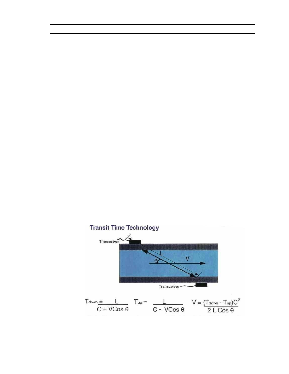
Velocity Measurement .................................................................. 1-3
Temperature Measurement............................................................ 1-4
Flow Meter Configurations.................................................................. 1-4
Multivariable Options ................................................................... 1-4
Line Size / Materials ..................................................................... 1-4
Flow Meter Electronics ................................................................. 1-4
Chapter 2 Installation
Installation Overview........................................................................... 2-1
Flow Meter Installation Requirements.......................................... 2-1
Unobstructed Flow Requirements................................................. 2-2
Series S34 Clamp-On Flow Meter Installation.................................... 2-3
Transducer Mounting Methods ..................................................... 2-3
Large Rail/Fixture System................................................................... 2-5
Adjacent Side Transducer Installation..................................... 2-5
Opposite Side Transducer Installation..................................... 2-7
Small Rail/Fixture System................................................................... 2-9
Adjacent Side Transducer Installation ........................................ 2-10
Wiring Connections ........................................................................... 2-12
Input Power Connections ............................................................ 2-12
Transducer Connections.............................................................. 2-12
Optional SonoConnect™Breakout Box Input Wiring ............... 2-13
4-20 mA Output Connections ..................................................... 2-17
Pulse Output Connections ........................................................... 2-18
Frequency Output Connections................................................... 2-18
Chapter 3 Operating Instructions
Flow Meter Display/Keypad................................................................ 3-1
Battery LEDS ................................................................................ 3-1
Start Up................................................................................................ 3-2
Using the Setup Menus........................................................................ 3-3
Programming the Flow Meter ....................................................... 3-4
Output Menu ................................................................................. 3-5
Display Menu................................................................................ 3-7
Alarms Menu................................................................................. 3-8
Totalizer #1 Menu ......................................................................... 3-9
Totalizer #2 Menu....................................................................... 3-10
Energy Menu....................................................................... 3-11
Fluid Menu .................................................................................. 3-12

Series S34 Instruction Manual Table of Contents
M-000-00030 0-4
Units Menu..................................................................... 3-13
Time and Date Menu...................................................... 3-14
Diagnostics Menu........................................................... 3-15
Calibration Menu ........................................................... 3-16
Password Menu .............................................................. 3-18
Chapter 4 Datalogging
Datalogging Overview......................................................................... 4-1
Programming the Unit to Log Data ..................................................... 4-1
Chapter 5 SonoConfig™ Instrument Interface Software
SonoConfig™Instrument Interface Software -The SonoPro®
Portable App ...................................................................................... 5-1
Chapter 6 Troubleshooting and Repair
Hidden Diagnostics Menus.................................................................. 6-1
Level One Hidden Diagnostics Values ......................................... 6-3
Level Two Hidden Diagnostics Values......................................... 6-4
Analog Output Calibration .................................................................. 6-7
Troubleshooting the Flow Meter ......................................................... 6-8
First Check Items................................................................................. 6-8
Record Values...................................................................................... 6-8
Determine the Fault ........................................................................... 6-10
Symptom: Output at No Flow ..................................................... 6-10
Symptom: Erratic Output ............................................................ 6-10
Symptom: No Output or Empty Pipe Detected........................... 6-10
Symptom: Inaccurate Flow Rate Reading................................... 6-11
Symptom: Unsatisfactory Correlation......................................... 6-12
Returning Equipment to the Factory.................................................. 6-14
Appendix A Product Specifications
Appendix B Flow Meter Calculations
Appendix C Sound Speed and Pipe Data
Appendix D Quick Start-Up Guide
Appendix E Glossary of Terms

Series S34 Instruction Manual Table of Contents
M-000-00030 0-5
Figures
1-1. Ultrasonic Flow Path .............................................................. 1-3
2-1. V - Two Traverse.................................................................... 2-3
2-2. W - Four Traverses ................................................................. 2-4
2-3. Z - One Traverse..................................................................... 2-4
2-4. Large Rail/Fixture System...................................................... 2-5
2-5. Spacing Locating Point on Large Rail/Fixture System........... 2-6
2-6. Opposite Side Transducer Installation, Front View................ 2-8
2-7. Opposite Side Transducer Installation, Side View ................. 2-8
2-8. Opposite Side Transducer Installation, Angled View............. 2-9
2-9. Small Rail/Fixture System...................................................... 2-9
2-10. Small Rail/Fixture System with Worm-Clamps ................... 2-10
2-11. Spacing Locating Point on Small Rail/Fixture System......... 2-11
2-12. AC Power Adapter................................................................ 2-12
2-13. Transducer Connection Points.............................................. 2-12
2-14a. SonoConnect™Wiring Pinout Diagram .............................. 2-13
2-14b. 3 and 4-Wire RTD Input Wiring........................................... 2-14
2-15. IDC Connector –Open Position ........................................... 2-14
2-16a. IDC Connector –Closed Position......................................... 2-15
2-16b. IDC Connector –Closed Position with Wires ...................... 2-15
2-17. Load Resistance versus Input Voltage.................................. 2-17
2-18. Isolated 4-20 mA Output Using External Power Supply...... 2-17
2-19. Isolated Pulse Output Using External Power Supply ........... 2-18
2-20. Isolated Frequency Output Using External Power Supply ... 2-18
3-1. Flow Meter Display/Keypad................................................... 3-1
4-1. Password Screen ..................................................................... 4-1
4-2. Output Menu........................................................................... 4-1
4-3. Diagnostics Menu ................................................................... 4-1
4-4. First Level of Hidden Diagnostics Menu................................ 4-2
4-5. Second Level of Hidden Diagnostics Menu ........................... 4-2
4-6. Logging Submenu................................................................... 4-2
4-7. Logging Interval ..................................................................... 4-3
4-8. Logging Variables .................................................................. 4-4
5-1. SonoConfig™App Icon ......................................................... 5-1
5-2. Screenshot of Waveforms Tab on SonoConfig™.................. 5-2
Tables
2-1. Recommended Pipe Length Requirements for Installation .... 2-2
2-2. SonoConnect™ DB25 Connector Pinout ............................. 2-16

Series S34 Instruction Manual Table of Contents
M-000-00030 0-6
Warnings and Cautions
Warning!
Consult the flow meter nameplate for specific flow meter approvals.
To avoid potential electric shock, follow National Electric Code or your local code when
wiring this unit to a power source. Failure to do so could result in injury or death. All AC
power connections must be in accordance with published CE directives. All wiring proce-
dures must be performed with the power off.
Always remove main power before disassembling any part of the flow meter.
Caution!
In order to achieve accurate and repeatable performance, the flow meter must be in-
stalled with the specified minimum length of straight pipe upstream and downstream of
the flow meter’s transducers.
Revision History
Rev. 1/2018 First Draft
Rev. 2/2019 Updated Menu Items and Added Section on Determin-
ing Faults
Rev. 7/2020 Updated Various Sections for Product Release
Rev. A New Release

Series S34 Instruction Manual Chapter 1 Introduction
1-1 M-000-00030
Chapter 1 Introduction
SonoPro®Ultrasonic Flow Meters
The VorTek Instruments’ SonoPro®Series Ultrasonic flowmeters provide a reli-
able solution for process flow measurement. From the externally mounted trans-
ducers, volumetric flow can be calculated non-invasively.
Multi-Parameter Mass Flow Meters
Mass flow can be determined by using the volumetric flow reading from
the clamp on ultrasonic transducers and measurements from the external
temperature sensors.
Volumetric Flow Meters
The primary sensing elements of the volumetric flow meter are the clamp
on ultrasonic sensors. The analog 4-20 mA output signals offer your
choice of volumetric or mass flow rate. Mass flow rate is based on a
constant value for fluid density stored in the instrument’s memory.
Both the mass and volumetric flow meters can be ordered with a local
keypad/display which provides instantaneous flow rate, total, and process
parameters in engineering units. A pulse output signal for remote totali-
zation and frequency output are also available. SonoPro®digital elec-
tronics allows for easy reconfiguration for most liquids. The VorTek Se-
ries SonoPro®Meters’ simple installation combines with an easy-to-use
interface that provides quick set up, long term reliability and accurate
volume or mass flow measurement over a wide range of flows, pressures,
and temperatures.
Using This Manual
This manual provides information needed to install and operate the Son-
oPro®Flow Meter.
•Chapter 1 includes the introduction and product description
•Chapter 2 provides information needed for installation
•Chapter 3 describes system operation and programming
•Chapter 4 provides information on datalogging
•Chapter 5 briefly describes the SonoPro® app and its functionality
•Chapter 6 covers troubleshooting and repair
Appendix A - Product Specifications, Appendix B –Flow Meter Calcu-
lations, Appendix C –Sound Speed and Pipe Data, Appendix D –Quick
Start-Up Guide, Appendix E –Glossary of Terms

Series S34 Instruction Manual Chapter 1 Introduction
1-2 M-000-00030
Note and Safety Information
We use note, caution, and warning statements throughout this book to
draw your attention to important information.
Warning!
Caution!
Note
This statement appears with
information that is important to
protect people and equipment
from damage. Pay very close
attention to all warnings that
apply to your application.
This statement appears with
information that is important
for protecting your equipment
and performance. Read and
follow all cautions that apply
to your application.
This statement appears with
a short message to alert you
to an important detail.
Receipt of System Components
When receiving a VorTek ultrasonic flow meter, carefully check the out-
side packing carton for damage incurred in shipment. If the carton is
damaged, notify the local carrier and submit a report to the factory or dis-
tributor. Remove the packing slip and check that all ordered components
are present. Make sure any spare parts or accessories are not discarded
with the packing material. Do not return any equipment to the factory
without first contacting VorTek Customer Service.
Technical Assistance
If you encounter a problem with your flow meter, review the configura-
tion information for each step of the installation, operation and set up pro-
cedures. Verify that your settings and adjustments are consistent with fac-
tory recommendations. Refer to Chapter 6 –Troubleshooting, for specific
information and recommendations.
If the problem persists after following the troubleshooting procedures
outlined in Chapter 6, contact VorTek Instruments, Technical Support at
(888) 386-7835 or (303) 682-9999 between 8:00 a.m. and 5:00 p.m.
MST. When calling Technical Support, have the following information
on hand:
•the serial number and VorTek order number (all marked on
the meter nameplate)
•the problem you are encountering, and any corrective action
taken
•application information (fluid, pressure, temperature, and
piping configuration)

Series S34 Instruction Manual Chapter 1 Introduction
1-3 M-000-00030
How the SonoPro®Flow Meter Operates
Velocity Measurement
The SonoPro Portable flowmeter operates on the transit time ultrasonic
measurement method. This type of measurement uses the basic fact that
the fluid's velocity influences the transmission speed of the ultrasonic
signal. This is analogous to a person paddling a canoe with the current
versus paddling against the current. The canoe can travel downstream
with the current faster than it can be paddled back upstream against the
current. The same is true for the sound waves as they travel with and
against the direction of fluid flow.
For the measurement, two ultrasonic transducers are mounted
onto the outside of the pipe. With one being downstream at a designated
distance from the other. The electronics send two pulses through the
pipe and into the fluid inside the pipe. One signal is sent with the direc-
tion of the flow, and the second is sent against the flow. The transducers
act as both transmitters and receivers. The transit time of the ultrasonic
signal moving in the direction of the flow is faster than that sent against
the flow. The meter's electronics read these two times and calculate the
time difference, ΔT, which can then be used to determine the average
flow velocity.
The SonoPro Portable electronics take into account the fluid flow
profile and apply a correction to the velocity reading to determine the
average flow through the pipe.
Ultrasonic Flow Path
Figure 1-1. Ultrasonic Flow Path

Series S34 Instruction Manual Chapter 1 Introduction
1-4 M-000-00030
Temperature Measurement
SonoPro®Flow Meters can use either an external 1000-ohm platinum re-
sistance temperature detector (PRTD) or an external temperature transmit-
ter (pending VorTek Instruments, LLC is consulted with prior) to measure
transducer temperature and to adjust for changes in the speed of sound due
to temperature changes.
Flow Meter Configurations
SonoPro®Ultrasonic Flow Meters are available with different
transducer frequencies for a wide variety of applications. Typi-
cal pipe sizes for each transducer type is listed below.
•2 MHz transducers –1/2” (15mm) pipe to 6” (150mm) pipe typical
•1 MHz transducers –2” (50mm) pipe to 20” (500mm) pipe typical
•.5 MHz transducers –12” (300mm) pipe to 200”(5000mm) pipe
typical
Installation and startup are covered in the following chapters.
Multivariable Options
The SonoPro®meter is available with the following options:
V, volumetric flowmeter; VER velocity and external RTD; VET velocity
and external temperature transmitter (pending VorTek Instruments, LLC
is consulted with prior); VERER, velocity, two external RTDs.
Line Size / Materials
The SonoPro®meter can be applied to line sizes from ½-inch (15mm) to
200-inch (5000mm), in a variety of materials and liners. The SonoPro®
meter comes preloaded with 22 pipe materials and six liner materials. If
the preloaded selections do not cover the intended application, a new
pipe or liner material can be entered pending the speed of sound of the
material is known.
Flow Meter Electronics
The SonoPro®Flow Meter electronics housing may be used indoors or
outdoors, including wet environments. Available input power options are
battery powered, or AC powered. Two analog output signals are availa-
ble to output any of the five process variables: mass flow rate, volumetric
flow rate, energy flow rate, temperature, or fluid density. A pulse output
signal for remote totalization and a scalable frequency output are also
available.
Flow Meters include a local 2 x 16-character LCD display housed within
the enclosure. Local operation and reconfiguration are accomplished us-
ing a tactile keypad.

Series S34 Instruction Manual Chapter 1 Introduction
1-5 M-000-00030
The electronics include nonvolatile memory that stores all configuration infor-
mation. The nonvolatile memory allows the flow meter to function immediately
upon power up, or after an interruption in power.

Series S34 Instruction Manual Chapter 2 Installation
M-000-00030 2-1
Chapter 2 Installation
Installation Overview
VorTek’s SonoPro®Ultrasonic Flow Meter installations are simple and
straightforward. Wiring instructions begin on page 2-12.
Flow Meter Installation Requirements
Before installing the flow meter, verify the installation site allows for the
following considerations:
1. Line temperature will not exceed the flow meter rating.
2. The location meets the required minimum number of pipe diam-
eters upstream and downstream of the sensor head as illustrated
in Table 2-1.
3. Safe and convenient access with adequate clearance for
maintenance purposes.
Also, before installation check your flow system for anomalies such as:
•leaks
•valves or restrictions in the flow path that could create disturb-
ances in the flow profile that might cause unexpected flow rate in-
dications
Warning!
Consult the flow meter nameplate for
specific flow meter approvals before any
hazardous location installation.

Series S34 Instruction Manual Chapter 2 Installation
M-000-00030 2-2
Unobstructed Flow Requirements
Select an installation site that will minimize possible distortion in the
flow profile. Valves, elbows, control valves and other piping compo-
nents may cause flow disturbances. Check your specific piping con-
dition against the examples shown below. To achieve accurate and
repeatable performance, install the flow meter using the recom-
mended number of straight run pipe diameters upstream and down-
stream of the sensors.
Note: For liquid applications in vertical pipes, avoid installing with
flow in the downward direction because the pipe may not be full at
all points. Choose to install the meter with flow in the upward direc-
tion if possible.
Piping Conditions
Condition
Pipe Diameters
Upstream
Downstream
One 90° elbow before meter
10D
5D
Two 90° elbows before meter
15D
5D
Two 90° elbows before meter,
out of plane
30D
10D
Reduction before meter
10D
5D
Expansion before meter
20D
5D
Partially open valve
30D
10D
Table 2-1. Recommended Pipe Length Requirements for Installation

Series S34 Instruction Manual Chapter 2 Installation
M-000-00030 2-3
Series S34 Clamp-On Flow Meter Installation
Prior to installing the SonoPro®transducers, a clean pipe surface needs to be
established. Remove any rust or loose paint or debris to make a smooth sur-
face. Choose a section of sound conducting pipe for installing the transduc-
ers. The application should be checked to ensure that air bubbles and partic-
ulate are at a minimum.
Transducer Mounting Methods
There are three typical mounting methods available. These include the Z
method, which is a single traverse across the pipe, the V method, which is
two traverses across the pipe, and the W method, which is 4 traverses across
the pipe. Each method has its own merits. The V method is by far the most
common for most applications from 4-inch to 12-inch pipe. The W method is
used for smaller pipes, i.e. line sizes ½-inch to 4-inch. The Z method is used
when there is poor signal strength or on pipes larger than 12-inch.
V –Two Traverse –Installation Method
1MHz transducers shown.
Figure 2-1. V - Two Traverses

Series S34 Instruction Manual Chapter 2 Installation
M-000-00030 2-4
W –Four Traverses –Installation Method
2 MHz transducers shown.
Figure 2-2. W - Four Traverses
Z –One Traverse –Installation Method
2 MHz transducers shown.
Figure 2-3. Z - One Traverse
Once the installation method is chosen, you will then need to refer to Chapter 3
for programming the unit for the actual application. The meter will calculate the
appropriate distance to mount the transducers from the data provided. The trans-
ducers can then be mounted to the pipe using the rail/fixture system.

Series S34 Instruction Manual Chapter 2 Installation
M-000-00030 2-5
Large Rail / Fixture System
Figure 2-4. Large Rail/Fixture System
Adjacent Side Transducer Installation
1. Program all the calibration menu items of the flow meter for the fluid and pipe
specifics to obtain the transducer mounting locations.
2. Position the rail/fixture system on the pipe in the desired location.
3. String the mounting chains from the front adjustable hook to the rear attachment
hook for both chains as show in Figure 2-4. Start with a loose fit.
4. Loosen the two set screws on the rightmost transducer mounting clamp and using
the scale etched on the front most rail, slide the clamp so that the back edge of
the side bracket is at the location determined by the flow meter. See Figure 2-5
for reference. Tighten the two set screws on the top of each side bracket after the
location is found.
5. Apply a thin coat of coupling grease to the transducers. If the coupling grease
that came with your SonoPro® flow meter unit runs out, contact VorTek Instru-
ments to order a replacement container.
6. Place the transducers in the left and right mounting bracket of the rail/fixture sys-
tem. If there is difficulty fitting the transducer in the leftmost mounting clamp,

Series S34 Instruction Manual Chapter 2 Installation
M-000-00030 2-6
loosen the two set screws on the top of each side bracket, slide the mounting
clamp slightly and then fit the transducer. Once the transducer is fitted, return the
mounting clamp to its original position (i.e. touching the end bracket connecting
the two rails) and tighten the two set screws. Tighten the screw with plastic knob
on the top of the mounting clamp so the end of the screw fits into the divot on the
top of the transducer.
7. Tighten the chain using the thumb nut on the front adjustable hook so the rail fits
tight on the pipe.
8. Tighten the screw with plastic knob on the top of the transducer mounting clamp
so the transducer fits tight on the pipe. Do not overtighten.
Figure 2-5. Spacing Locating Point on Large Rail/Fixture System*
*Note: Scale not shown here. Scale to be included with actual Large Rail/Fixture System

Series S34 Instruction Manual Chapter 2 Installation
M-000-00030 2-7
Opposite Side Transducer Installation
1. Program all the calibration menu items of the flow meter for the fluid and pipe
specifics to obtain the transducer mounting locations.
2. Position the first transducer mounting clamp on the pipe in the desired location.
3. String the mounting chain from the front adjustable hook to the rear attachment
hook. Start with a loose fit.
4. Apply a thin coat of coupling grease to the first transducer. If the coupling grease
that came with your SonoPro® flow meter unit runs out, contact VorTek Instru-
ments to order a replacement container.
5. Place the transducer in the mounting clamp. Tighten the screw with plastic knob
on the top of the mounting clamp so the end of the screw fits into the divot on the
top of the transducer.
6. Tighten the chain using the thumb nut on the front adjustable hook so the mount-
ing clamp fits tight on the pipe.
7. Tighten the screw with plastic knob on the top of the transducer mounting clamp
so the transducer fits tight on the pipe. Do not over tighten.
8. Position the second transducer mounting clamp on the pipe at the location
determined by the flow meter and 180 degrees around the pipe from the first one.
See Figure 2-6, 2-7, and 2-8 for reference.
9. String the mounting chain from the front adjustable hook to the rear attachment
hook. Start with a loose fit.
10. Apply a thin coat of coupling grease to the second transducer. If the coupling
grease that came with your SonoPro® flow meter unit runs out, contact VorTek
Instruments to order a replacement container.
11. Place the transducer in the mounting clamp. Tighten the screw with plastic knob
on the top of the mounting bracket so the end of the screw fits into the divot on
the top of the transducer.
12. Tighten the chain using the thumb nut on the front adjustable hook so the mount-
ing clamp fits tight on the pipe.
13. Tighten the screw with plastic knob on the top of the transducer mounting clamp
so the transducer fits tight on the pipe. Do not overtighten.

Series S34 Instruction Manual Chapter 2 Installation
M-000-00030 2-8
Figure 2-6. Opposite Side Transducer Installation, Front View
Figure 2-7. Opposite Side Transducer Installation, Side View

Series S34 Instruction Manual Chapter 2 Installation
M-000-00030 2-9
Figure 2-8. Opposite Side Transducer Installation, Angled View
Small Rail / Fixture System
Figure 2-9. Small Rail/Fixture System
Table of contents
Other VorTek Measuring Instrument manuals
Popular Measuring Instrument manuals by other brands

Leader
Leader Search user manual

Bühler technologies
Bühler technologies GAS 222.21 Assembly, installation and operation instructions

Oval
Oval WaterMaster instructions

Asco
Asco 5101 Operation manual

BEG
BEG LUXOMAT Indoor 180N-R/2W-UK Installation and operating instruction

Rohde & Schwarz
Rohde & Schwarz FSMR3000 Getting started