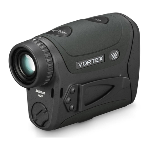
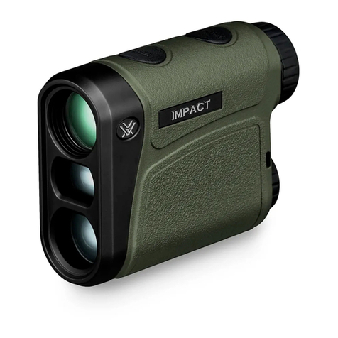
Vortex IMPACT 4000 Instruction manual

QUICK START MANUAL

IMPACT®4000
2 3
SPECIFICATIONS��������������������������������� 4
IMPACT®4000 BALLISTIC LASER RANGEFINDER ������� 6
PRODUCT WALKAROUND��������������������������� 7
BUTTON NAVIGATION ����������������������������� 8
BASIC OPERATION ������������������������������ 10
Battery Installation and Replacement����������������� 10
Power Up ������������������������������������ 11
Low Battery Icon ������������������������������� 11
Compass Calibration ���������������������������� 12
MOUNTING������������������������������������� 17
ZEROING �������������������������������������� 18
SETUP MENU ����������������������������������� 20
Range Mode Selection ��������������������������� 20
Target Mode Selection ��������������������������� 24
Profile Selection ������������������������������� 25
Range Cards ���������������������������������� 30
SETTINGS MENU �������������������������������� 32
Changing Settings on the Impact®4000 ��������������� 32
Backlight Selection ����������������������������� 33
Compass ������������������������������������� 33
Unit Selection ��������������������������������� 34
Auto-Shutoff Selection ��������������������������� 34
Visible Laser Selection ��������������������������� 35
Reset Selection �������������������������������� 35
Devices ������������������������������������� 36
CONNECTED DEVICES MENU����������������������� 36
Ballistics������������������������������������� 39
Weather ������������������������������������� 40
Wind���������������������������������������� 40
WEATHER INFORMATION ������������������������� 41
Wind Screen ���������������������������������� 41
Weather Screen�������������������������������� 43
Wind and Target Direction Screen ������������������� 43
RANGEFINDING TIPS����������������������������� 44
MAINTENANCE���������������������������������� 45
TROUBLESHOOTING GUIDE ������������������������ 46
Default Profiles �������������������������������� 48
INDEX ���������������������������������������� 48
TABLE OF CONTENTS

IMPACT®4000
4 5
SPECIFICATIONS
DISPLAY SIZE 1.3" (33mm)
DISPLAY TYPE LCD
DEER RANGE TREE RANGE
MAX
REFLECTIVE
RANGE
NORMAL MODE Up to 1200 yds.
(1097m)
Up to 2200 yds.
(2012m)
Up to 2400 yds.
(2195m)
ELR MODE Up to 1500 yds.
(1372m)
Up to 2500 yds.
(2286m)
Up to 4000 yds.
(3658m)
MINIMUM RANGE 5 yds. (4.5m)
ACCURACY
± 0.5 yds. @ < 100 yds.
± 1 yd. @ ≥100 yds. & ≤1000 yds.
± 3 yds. @ > 1000 yds.
MAX ANGLE READING ± 89˚
BATTERY TYPE CR123
LENGTH 4.6" (117mm)
HEIGHT 2.5" (64mm)
WIDTH 3.2" (81mm)
WEIGHT W/ BATTERY 16.0 oz. (453.6kg)

IMPACT®4000
6 7
IMPACT®4000
BALLISTIC LASER RANGEFINDER
The Impact®4000 takes the guesswork out of
long-range shooting with quick, accurate ballistic
corrections. Everything you need to generate point-
and-shoot target solutions without ever coming off the
gun. This advanced, rail-mounted laser rangefinder
delivers key range, ballistic, and weather data
via the integrated GeoBallistics®solver, on-board
Environmental Sensors, and our patented Wind
Bearing Capture Mode. Mounts to any picatinny-style
rail or rings with a diving board mount.
The Impact®4000 pairs, via Bluetooth®, with your
mobile device and the GeoBallistics®App. Scan the
QR code below to download the GeoBallistics®App
with your Apple or Android device.
The QR code below will also give access to
instructional videos.
SCAN QR CODE TO GET STARTED
PRODUCT WALKAROUND
Settings
Button
Environmental
Sensors
Picatinny Mount
& 1/2" Lug Nuts
Laser
Emitter/Receiver
Left Arrow Button Up Arrow Button
Down Arrow Button Right Arrow Button
Elevation Turret
Backlight Button
Windage Turret
Display Screen
Measure Button
Battery Compartment
Wind Bearing Capture
(W.B.C.) Button
Visible Laser
Enable/Disable Switch
Images are for representation only.
Product may vary slightly from what is shown.

IMPACT®4000
8 9
BUTTON NAVIGATION
SETTINGS
BUTTON • Opens and Closes the Settings Menu
WIND BEARING
CAPTURE BUTTON
• Opens and Closes the Wind Bearing
Capture Screen
MEASURE
BUTTON
• Takes Range
• Selects Menu Options
UP ARROW
BUTTON
• Navigates Up in Menu Structure
• Increases Manually Inputted Values
DOWN ARROW
BUTTON
• Navigates Down in Menu Structure
• Decreases Manually Inputted Values
LEFT ARROW
BUTTON
• Navigates Back in Menu Structure
• Navigates Left when Manually
Inputting Values
RIGHT ARROW
BUTTON
• Navigates Deeper into the Menu Options
• Navigates Right when Manually
Inputing Values
BACKLIGHT
BUTTON
BACKLIGHT
BACKLIGHTBACKLIGHT • Turns ON/OFF Display Backlight
Note: To change the orientation of the Arrow Buttons on the
Bluetooth®Remote, press and hold the button you wish to be
“Up” and the “Measure” button for three seconds until the
light blinks green.
IMPACT®4000 BUTTONS
Wind Bearing
Capture Button
(W.B.C.)
Backlight Button
Settings Button
Left Arrow Button
Up Arrow Button
Right Arrow Button
Measure Button
Down Arrow Button
BLUETOOTH® REMOTE BUTTONS
Up Arrow Button
Left Arrow Button
Measure Button
Right Arrow Button
Down Arrow Button

IMPACT®4000
10 11
BASIC OPERATION
Battery Installation and Replacement
To insert a new battery, flip up the finger tab on the
Battery Cap and unscrew, counterclockwise, to remove.
Insert a CR123 battery with the negative side (-) facing
outwards. Reinstall the Battery Cap and ensure it is
tightly closed.
To insert a battery into the
Bluetooth®Remote, utilize the
multi tool to unscrew the Battery
Cap counterclockwise, to remove.
Insert a CR2032 battery with the
positive side (+) facing outwards.
Reinstall the Battery Cap, turning
clockwise, and utilize the multi
tool to ensure it is tightly closed.
Power Up
Once the battery is installed, the Impact®4000 is in
ready condition – the normal power-off condition when
not ranging. To power up the Impact®4000 from ready
condition, press and release the “Measure” button.
The default ranging screen, HCD, will display. To turn
off the Impact®4000, press and hold the “Measure”
button for three seconds. The Impact®4000 Auto-
Shutoff default is three minutes. For instructions to
change the Auto-Shutoff to one minute or disable
Auto-Shutoff, see page 34.
Low Battery Icon
The Low Battery Icon
displays once the battery
reaches 20% life and stays
on until there is no power or
the battery is replaced.

IMPACT®4000
12 13
Compass Calibration
Compass calibration is important for the accuracy
of Wind Bearing Capture Mode. Read steps 1-5 of
“Calibrating the Compass and Inclinometer” section
before performing the following steps. The Impact®
4000 needs to be calibrated during initial setup and
should be re-calibrated every time you significantly
change location, typically 30 miles or more. Calibrate
your Impact®4000 outside and away from large metal
structures or objects.
Scan the QR Code below for links to video instructions
on how to calibrate the Impact®4000.
SCAN QR CODE TO GET STARTED
Important: Do not hit any buttons on the Impact®4000
during this process unless specifically instructed to do
so in the following steps.
Important: Remove the Impact®4000 from the rifle
before beginning the calibration process.
Calibrating the Compass and Inclinometer
To navigate to the Compass Screen, press the “Settings”
button. Navigate to and select “Settings” to open the
Settings Menu. Navigate to and select “Compass” to
open the Compass Screen. To begin calibration, select
“Calibrate” on the Compass Screen. Select “Begin” and
complete the following steps when prompted.

IMPACT®4000
14 15
1. Rotate the rangefinder in a figure eight for 15
seconds. Press the “Measure” button to continue.
2. Rotate the rangefinder horizontally for 15 seconds.
Press the “Measure” button to continue.
3. Rotate the rangefinder
vertically for 15 seconds.
Press the “Measure” button
to continue.
4. Turn the rangefinder onto its left side and rotate it
horizontally for 15 seconds. Press the “Measure”
button to continue.
5. Turn the rangefinder onto its right side and rotate
it horizontally for 15 seconds. Press the “Measure”
button to complete.

IMPACT®4000
16 17
MOUNTING
Once your Impact®4000 has been calibrated it can be
mounted to your weapon. Prior to mounting the laser
rangefinder ensure your riflescope is mounted and
zeroed to your desired zero distance.
1. Mount your picatinny diving board mount or
picatinny accessory rail and tighten to the
manufacturer’s torque specifications using a
torque wrench.
2. Place the Impact®4000 Picatinny Mount on
the rail and position it so its placement does not
interfere with the adjustment of the turrets.
3. Using the provided 1/2" Nut Diver Tool, tighten the
1/2" Lug Nuts to 45 in-lbs. Using a torque wrench
is recommended if available.
Note: If the Impact®4000 is mounted on the side of the gun,
the screen with auto-rotate accordingly.
The screen will read “Success” if the compass has
successfully calibrated. If the screens reads “Fail - Try
Again”, press the “Measure” button to restart the
calibration and repeat this process until the Impact®
4000 is successfully calibrated.

IMPACT®4000
18 19
ZEROING
To ensure the accuracy of the Impact®4000 range and
ballistic solutions it must be zeroed parallel to your
riflescope. This allows you to aim the device with the
center of your reticle at all distances. To zero, follow
the steps below:
1. Before starting, your riflescope must be properly
mounted and zeroed. Your Impact®4000 must be
calibrated and then mounted to your weapon.
2. Place the Small Reflective Target Sticker on the
Alignment Target at the same measured offset
that the Impact®4000 is mounted from the
center of the riflescope. Find common mounting
offsets marked on the Alignment Target. Your
offset may be different, it is good to measure left/
right and up/down offset to the nearest 1/4" to
verify the sticker placement.
Height Over Scope Center = Rangefinder Offset
REFLECTIVE TAPE
REFLECTIVE TAPE
Note: The Alignment Target grid consists of 1" squares for
easy measurements.
3. Hang the Alignment Target, in a safe direction,
at 50-100 yards using the Large Reflective Tape
Strips. Use one piece of tape on the top of the
target and one on the side of the target.
4. Turn the Visible Laser Switch on the side of the
laser rangefinder to “Enable” utilizing the provided
Torx®T-10 Tool.
5. Turn the Visible Laser ON from the Settings Menu.
To do so, press the “Settings” button. Navigate
to and select “Settings”. Navigate to and select
“Visible Laser” and select “ON”.
Note: While the Visible Laser is ON, all ranging and
ballistic functions are disabled.
6. Utilize the Large Reflective Tape Strips to locate
the target with the Visible Laser. The Visible Laser
may not be well aligned to start.
7. Align your riflescope’s crosshair to the center dot
of the Alignment Target, and use the Flat Head
Tool to adjust the Elevation and Windage Turrets
to align the Visible Laser to the Small Reflective
Target Sticker.
8. Your Impact®4000 is now zeroed parallel to
your riflescope.
9. Turn the Visible Laser Switch on the side of
the laser rangefinder to “Disable” utilizing the
provided Torx®T-10 Tool and turn the Visible
Laser OFF from the Settings Menu following the
instructions from Step 5.
Once the Impact®4000 is calibrated, mounted, and
zeroed it must be setup to your specifications to ensure
accurate ballistic solutions for your shooting scenario.
IMPACT®4000
20 21
HCD Mode
The Horizontal Component Distance Mode (HCD) will
be your primary mode when not using the on-board
ballistic solver. The yardage number displayed is the
critical horizontal component distance. The displayed
HCD yardage number is corrected for shot angle and
needs no extra user input; shooters simply use the
appropriate level ground bullet drop for the range
displayed and shoot.
Line of Sight (LOS)
2091 YARDS
Horizontal Component
Distance (HCD)
1811 YARDS
30˚
Note: To correctly account for wind, you need to know the line
of sight distance to the target as it is based on how far the
bullet travels to the target. This can be achieved using the
LOS or BAL Mode.
SETUP MENU
Changing Modes on the Impact®4000
The Impact®4000 is factory set to the angle
compensating HCD Range Mode, Normal Target Mode,
.308 Winchester Profile, and Range Card OFF.
To Change Modes:
Press the “Measure” button
to power on the unit, and
then press the “Settings”
button to open the Main
Menu. Navigate to and
select “Setup”. In the Setup
screen, you can access both
Range and Target Mode
Selection screens.
As you progress through the Mode Selection, you may
exit at any time and save your settings by pressing the
“Settings” button and the unit will then return to the
Range Ready screen.
Range Mode Selection
Choose between HCD, LOS and BAL Modes
On the Setup Menu screen,
toggle to and select “Range
Mode”. You can choose
between the HCD, LOS
and BAL displays. The
selected mode will be
designated with an arrow.
Return to the Setup Menu
screen and continue to
Target Mode Selection.

IMPACT®4000
22 23
BAL Mode
When in Ballistics (BAL) Mode, in addition to the
range, the slope incline in degrees, riflescope units
in MOA, MIL, or inches, and the ballistic correction
based on the selected profile are also displayed.
To use the on-board ballistic solver, you need to
be in BAL Mode. When in BAL Mode, line of sight
measurements are used to calculate ballistic solutions.
Riflescope
Unit
Elevation
Adjustment
Windage
Adjustment
Distance
Unit
Inclination
Angle
Bluetooth®
Status
LOS Range
Distance
LOS Mode
The Line of Sight (LOS) Mode is intended for rifle
shooters who are using slope correcting ballistic drop
data cards, ballistic cell phone applications, or other
devices with ballistic programs and who are shooting
at distances beyond 500 yards and with slopes greater
than 15 degrees.
The range number displayed in LOS Mode is the
actual line of sight range with no ballistic correction
for slope. Most of the commonly used ballistic devices
can provide independent slope correction for bullet
drop data and require actual line of sight range input.
Using the LOS range when calculating bullet wind
drifts under these steep slope/long range conditions
will provide a higher degree of accuracy than using the
HCD range. While in LOS Mode, inclination angle of
the target is also displayed on the screen. Downward
angles are denoted with negative numbers.
Inclination
Angle
Bluetooth®
Status
LOS Range
Distance
Distance
Unit
Range
Mode

IMPACT®4000
24 25
Profile Selection
The Impact®4000 comes with ten common
default Ballistic Profiles. The profiles can be used as
is or customized to reflect your specific rifle and
bullet combination.
The default profiles include .308 Winchester, 6.5
Creedmoor®, .223/5.56, .30-06, .300 Winchester
Magnum, .270 Winchester, 7mm Remington Magnum,
.243 Winchester, .22-250 Remington, .22 Long Rifle.
On the Setup Menu screen, toggle to and select
“Profile”. You can choose between the ten ballistic
profiles. The selected profile will be designated with
an arrow.
To edit a profile, ensure it is designated with the arrow
and then select it. You are able to customize the Bullet
information, Rifle information, or Rename the profile.
Target Mode Selection
The Impact®4000 provides two target modes:
Normal Mode and Extended Laser Range (ELR) Mode.
On the Setup Menu screen, toggle to and select
“Target Mode”. You can choose between Normal and
ELR Mode. The selected mode will be designated with
an arrow. Return to the Setup screen and continue to
Profile Selection.
Normal Mode
The Impact®4000 comes preset to Normal Mode.
This is the standard mode providing the target’s range
with the strongest range result. Normal Mode is the
recommended target mode for most situations.
Extended Laser Range (ELR) Mode
This mode allows for ranging smaller, less reflective
targets at extended distances. It is ideal for ranging
when Normal Mode is unable to obtain a desired range.
A longer response time may be required to receive the
desired range.

IMPACT®4000
26 27
In general, G1 is better for flat-based bullets typically
used with pistols and muzzleloaders. G7 is more
common and better for longer, boat-tailed bullets
which are common for center fire cartridges.
VS
G-7G-1
Note: Drag Model options: Multi G1, Multi G7 or CD, can be
imported from the GeoBallistics®App. When using these the
ballistic coefficient will read “MULTI” or “CD” and the Drag
Model will read “MULTI G1”, “MULTI G7” or “CD” based on
your selection.
Rifle Information
To edit the Rifle information, toggle to and select
“Rifle”. To edit a field, when highlighted, press the
“Right Arrow” button to select the data and use the up
and down arrows to modify the data.
Bullet Information Screen
To edit the Bullet information, use the up and down
arrows to toggle to and select “Bullet”. To edit a field,
when highlighted, press the “Right Arrow” button
to select the data and use the up and down arrows
to modify the data. Press the “Left Arrow” button to
return to the field list. Return to the previous screen to
continue to the Rifle information.
Caliber (in):
The bullet’s diameter in inches.
Weight (gr):
The bullet’s weight in grains.
Length (in):
The bullet’s length in inches.
Ballistic Coefficient:
The bullet’s ballistic coefficient as it correlates to
the drag function.
Note: Find these values on the ammunition’s box or on the
manufacturer’s website.
Drag Model – G1 vs G7
This information may be printed on the box if you are
using manufactured bullets. If you are using custom
loads, use the Drag Model listed on the packaging
for your bullet. If the Drag Model is not listed on the
packaging, this information can usually be found on
the bullet/ammo manufacturer’s website.

IMPACT®4000
28 29
Muzzle Velocity
Muzzle Velocity (MV) is the projectile’s speed as it
leaves the muzzle. You can find this information on
the packaging from most ammunition manufacturers,
or their websites. We highly recommend that you
use a chronograph to verify this information. The
measurement units can be set to standard (ft/s) or
metric (m/s) in the Settings Menu.
An MV Temp Table can be input via the GeoBallistics®
App. Scan the QR code on page 6 to see the Full
Product Manual for directions on how to do so. If an
MV Temp Table is active, the calculated MV will be
displayed with a T preceding it. Ex: T2743.
Sight Units
Choose the Sight Units you would like to have your
drop chart displayed with MRAD, MOA, or inches.
This information will be based off the angular unit of
measurement your riflescopes turrets and reticle are
laid out in.
Renaming a Ballistic Profile
To rename the Ballistic Profile, toggle to and select
“Rename”. Use the left and right arrow buttons to
select which character to change and the up and down
arrow buttons to toggle through the keyboard options.
After renaming the profile, return to the Setup screen.
Sight Height
Height from the center of the rifle bore to the center
of the optic. The measurement units can be set to
standard (inches) or metric (centimeters) in the
Settings Menu.
Sight Height
Zero Range
The distance at which you have zeroed your rifle. The
measurement units can be set to standard (yards) or
metric (meters) in the Settings Menu.
Barrel Twist Rate
Barrel Twist Rate is the distance covered for each
revolution of the bullet within the barrel. For example,
if your barrel is denoted as “1:8”, this means the
bullet will complete one full rotation every 8 inches
and you should enter “8” into this space. This
information may be marked on the rifle barrel, or on
the manufacturer’s website. Update the Twist Rate to
match your rifle.
Note: If your barrel has a left-hand twist, you must enter the
Twist Rate via the GeoBallistics®App and denote it with a
negative or minus sign. A negative sign will then be displayed
before the Twist Rate on the device. If you cannot find the
twist rate for your barrel, we recommend inputting 10.

IMPACT®4000
30 31
Building a Range Card
Line up your riflescope to
your target and press the
“Measure” button to range.
The measured range will
show up as A. You can
change this range until you
are satisfied with the
distance by pressing the
“Measure” button to range
again or changing it
manually by pressing the
“Right Arrow” button to
select the range and adjust
the distance using the up
and down arrow buttons. If
you are satisfied with your
range, move onto the next
target by pressing the
“Down Arrow” button to
move to letter B. Continue
these steps until all the
targets are entered.
To save the Range Card,
press the “Settings” button
and select “Yes” when asked
to save changes.
Note: The Range Card will save the target distance,
inclination, and direction. If you update your wind or
weather parameters, your range card ballistic solutions will
automatically update accordingly.
Range Cards
A Range Card can help
provide quick and accurate
ballistic solutions that can
be used again and again.
The Impact®4000 has
the capability to store ten
Range Cards. Within each
Range Card, ten targets
can be stored.
To build a Range Card, navigate to and select “Range
Card” on Setup Menu. On the Range Card screen,
select “ON” to turn on the Range Card feature.
To select which Range Card
you’d like to edit, toggle to
and select “Card Manager”.
Select which card you’d like
to edit. To rename the
Range Card, press the
“Right Arrow” button and
select “Rename”. Use the
left and right arrow buttons
to select which character to
change and the up and
down arrow buttons to
toggle through the keyboard
options. After renaming the
Range Card, press the
“Settings” button to exit the
menu and return to the
Range Ready screen.

IMPACT®4000
32 33
Backlight Selection
Choose Between Five Brightness Settings
The Impact®4000 features
five Backlight brightness
settings. Toggle through the
five settings and select your
desired brightness level.
Return to the Settings Menu.
Note: This adjusts the brightness of the Backlight. To turn
the Backlight on/off, press the “Backlight” button under the
Display Screen on the Impact®4000.
Compass
The Impact®4000 compass needs to be calibrated
during initial setup and should be re-calibrated every
time you significantly change location, typically 30
miles or more. Calibrate your Impact®4000 outside
and away from large metal structures or objects.
For instructions on how to
calibrate your Impact®4000
see the “Calibrating the
Compass and Inclinometer”
section on pages 13-16.
Note: You need to remove the Impact®4000 from your rifle
before calibrating.
To turn OFF the Range Card, press the “Settings”
button to return the Main Menu, select “Setup”, toggle
to and select “Range Card” and toggle to and select
“OFF”. Return to the Main Menu and continue to
adjust the Impact®4000 Settings.
SETTINGS MENU
Changing Settings on the Impact®4000
The Impact®4000 is factory set to Brightness Level 3,
Standard Units, Auto-Shutoff set to 3 minutes and the
Visible Laser set to OFF.
To Change Settings:
Press the “Settings”
button to open the Main
Menu. Navigate to and
select “Settings” to open
the Settings Menu. In the
Settings Menu, you can
access Backlight, Compass, Units, Auto-Shutoff and
Visible Laser settings. This menu is also where you can
reset your device to factory settings.

IMPACT®4000
34 35
Visible Laser Selection
The Impact®4000 comes equipped with a Visible
Laser to be used for zeroing the rangefinder. The
Visible Laser Switch must be enabled on the side of
the rangefinder using the included Torx®T-10 Tool to
function. If the Visible Laser is ON, the red alignment
laser will turn on. The use of the Visible Laser is only
permitted for zeroing. No range or ballistic solutions
can be calculated while the Visible Laser is ON. Return
to the Settings Menu. Turning the Visible Laser Setting
to OFF will re-enable ranging functions of the device.
Reset Selection
The Reset screen can be
used to restore the Impact®
4000 to factory settings.
Select “Erase All Data
& Restore” to reset the
device. Press the “Setting”
button to return to the Main
Menu and continue on to
Connective Devices.
Note: This will clear your range cards, weapons profiles, and
all other selections made. If you wish to save a copy of your
range cards and profiles prior to performing this step, make
sure to sync your device with the GeoBallstics®App.
Unit Selection
The Impact®4000 offers the selection of standard or
metric units. This will set all applicable Riflescope
Units, Weather Units, and Distance Units to that
unit of measure. To customize each unit individually,
navigate to and select “Custom”. Press the “Right
Arrow” button to open the Custom screen, where
you can edit Riflescope Units, Weather Units, and
Distance Units independently. To change the unit of
measure, navigate to the
unit you’d like to change,
press the “Right Arrow”
button to select the current
unit of measure, then use
the Up and Down Arrow
Buttons to toggle through
the unit options. Once you
have selected your desired
unit of measure, press the
“Left Arrow” button to
return to the list. Repeat
until all units are set to
your preferences. Return to
the Settings Menu to adjust
the Auto-Shutoff settings.
Auto-Shutoff Selection
The Impact®4000 offers
two Auto-Shutoff options: 1
minute and 3 minutes. It is
also possible to turn off the
Auto-Shutoff feature. Once
you have made your desired
selection, return to the
Settings Menu.

IMPACT®4000
36 37
View
On the View screen, you
can view which devices are
currently connected via the
Vortex Relay™Network. To
show up on the network, the
devices must be previously
added and turned on. When you select a device, you
can see the latest firmware and software information
by pressing the “Right Arrow Button”.
Note: A network is a group of devices and mobile applications
that communicate to each other. Devices can only be
connected to one network at a time.
Note: On the Range Ready screen, the Bluetooth®icon will
change to a number to indicate how many devices are on the
network. A “1” indicates that the Impact®4000 is the only
device on the network. A “4” would indicate that 3 other
devices are on the network with the Impact®4000.
Add
The Add screen is where
you can add devices to
your network. The Impact®
4000 will automatically find
all compatible devices on
the Vortex Relay™Network
that are turned on and
within Bluetooth®range
(approximately 30 feet) that
are not already connected to another network. Select
the device from the list that you wish to add. When the
new device joins the network, if the profile or range
cards are different, you will be asked on both devices
which device’s information should be used. Repeat to
add any additional devices.
Note: When adding a Bluetooth®Remote to your Impact®
4000 device, it will automatically pair and control your device.
CONNECTED DEVICES MENU
The Impact®4000 can
connect with the
GeoBallistics®App for quick
customization and to the
included Bluetooth®Remote
for easy adjustments without
leaving the shooting position via the Vortex Relay™
Network. To manage connected devices, navigate to
and select “Connected Devices” from the Main Menu.
Note: The Impact®4000 can operate as a stand-alone device.
Connection to other devices such as the GeoBallistics®App
and the Bluetooth®Remote are not required.
Devices
The Devices screen allows you to view, add, or remove
devices and connect your Bluetooth®Remote to the
devices you’d like for it to control.

IMPACT®4000
38 39
Blinking Red
•
Not On a Network
Blinking Orange
• On a Network
• Not Connected to
a Device
Blinking Green
• On a Network
• Communicating
With a Device
Note: When the Bluetooth®Remote blinks red, it is not on
a network. When it blinks orange, it is on a network, but not
connected to any other device. When it blinks green, it is
on the network and communicating with another device on
the network.
Note: You are not able to connect the remote to control the
GeoBallistics®App.
To manually disconnect the Bluetooth®Remote from
the Impact®4000, but keep it on the network, press
and hold the remote’s “Left Arrow Button” and “Right
Arrow Button” together for three seconds.
The Bluetooth®Remote can also be disconnected from
the network manually by pressing and holding the
remote’s “Up Arrow Button” and “Down Arrow Button”
together for three seconds.
Ballistics
Once you have connected
your devices to your network,
select “Ballistics” on the
Connected Devices Menu
and select which device’s
on-board solver you’d like
to provide ballistics. The
selected device will be
denoted with an arrow.
Remove
The Remove screen is where
you can remove devices from
your network. Select the
device you wish to remove
from the network.
Note: You can remove your Impact®4000 device from your
network. You would need to do this if you are shooting with a
friend and wish to join their network or if you sell or lend your
Impact®4000 to someone else.
Connect Remote
The Connect Remote
screen is where you can
control which device your
Bluetooth®Remote is
paired to. Before doing so,
you must make sure to add
the Bluetooth®Remote
to your network via the
Add screen. Select your
remote, and then select
which device you’d like to
connect your remote to.
Connected devices will
be denoted with an arrow.
Return to the Connected
Devices Menu to select
which source you’d like to
provide which information.
This manual suits for next models
1
Table of contents
Other Vortex Measuring Instrument manuals

Vortex
Vortex RWG Series User manual

Vortex
Vortex Ranger 1500 User manual

Vortex
Vortex Razor HD 4000 GB Instruction manual

Vortex
Vortex RANGER 1300 User manual

Vortex
Vortex Viper HD 3000 User manual

Vortex
Vortex Impact 850 User manual

Vortex
Vortex BLUEONE BWO 155ZM User manual

Vortex
Vortex Viper HD 3000 User manual

Vortex
Vortex Razor HD 4000 User manual

Vortex
Vortex Razor HD 4000 GB User manual