CrossFire™HD 1400
10 11
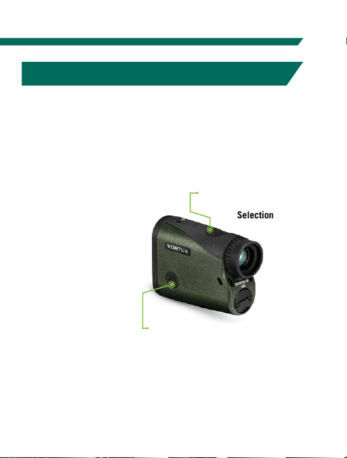
Brightness Selection
Choose between Five Brightness Settings
The Crossfire™HD 1400 provides
five illumination settings. Press the
“Measure” button to toggle through
the five Brightness settings. Press
the “Menu” button to save your
desired setting. and move back to
the Range Mode Setting.
To exit Mode/Display Selection and save settings, press
and hold the “Menu” button for two seconds. Settings
will also save when the Crossfire™HD 1400 powers
down automatically.
TARGETING MODE EXPLANATIONS
The Crossfire™HD 1400 provides three target modes:
Normal Mode, First Mode, and Last Mode.
Normal Mode
Your Crossfire™HD 1400 comes preset to Normal target
mode. This is the standard mode providing the range of
the target with the strongest range result. Normal Mode is
the recommended target mode for most situations.
First Mode
This mode displays the closest
distance when ranging. This mode
is ideal for ranging a smaller target
in front of other larger or more
reflective objects.
Note: If unsure about the range, simply
range again.
Last Mode
This mode displays the farthest
distance when ranging. This mode
is ideal for ranging a specific target
behind a group of objects like
brush, trees, rocks, etc.
Note: If unsure about the range, simply
range again.
For additional information on Targeting Modes, please visit
VortexOptics.com
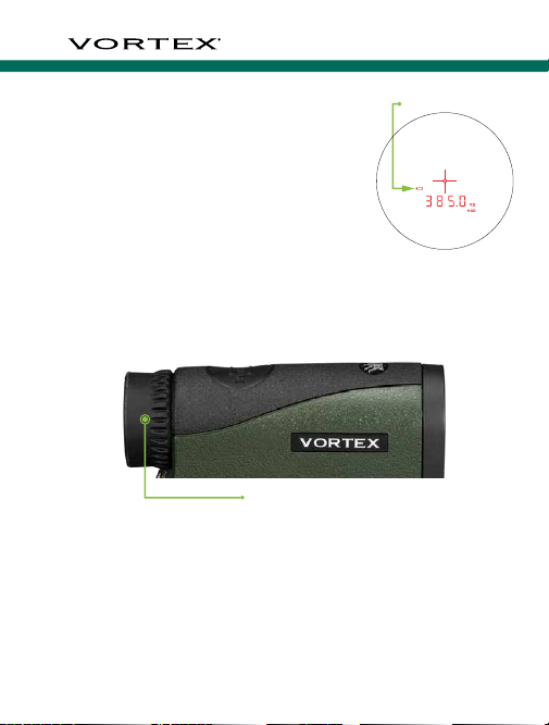
Range captured