Vortex RH9521-12 User manual

RAINWATER HARVESTING
INSTALLATION GUIDE
RH9521-12
High Capacity Vortex Rainwater Fine Filter
for
Above or Below Grade Application

RH9521-12 Vortex Filter
Operation and Maintenance
Overview
The RH9521-12 Vortex F lter harvests up to 95% of the
rooftop ra nwater runoff from a roof area up to 33,000 sq.
ft. Part culate s separated and d verted from the ra nwater
through the vortex act on to protect the harvested water
qual ty pr or to enter ng the storage tank (c stern). The
Vortex F lter s used pr mar ly for below ground nstallat ons
where mult ple downspouts are connected to a s ngle trunk
l ne. The RH9521-12 can be used for above ground
appl cat ons and can be mounted w th a custom-made
stand or bracket, suppl ed by others. The trunk l ne feeds nto the centrally located Vortex F lter.
• Part cles larger than 380 m crons are d verted nto the storm dra n.
• The full cross-sect on of the ra nwater dra nage system rema ns cont nuously open n the
RH9521-12 system. There are no restr ct ons or obstruct ons n the f lter on wh ch debr s can
collect.
• The f lter element develops t’s max mum eff c ency when the f lter mesh has been completely
wetted. After a dry per od, th s can take up to 2 m nutes. Th s f rst flush act on d verts the ent re
n t al flow of water nto the storm dra n. After the f lter s completely saturated, f ltered water w ll
be del vered to the c stern.
• If necessary, (for deeper underground nstallat on) an extens on can be nstalled up to ground
level (accessory).
• The ra nwater nlet can be turned 360° n relat on to the lower sect on. The central dra n outlet s
vert cal so that p pes can be connected n any d rect on.
Installation
Pre-plann ng s cr t cal. It s recommended that the f lter be n place before trunk l nes are run and the
tank s bur ed for below ground appl cat ons and pr or to construct ng a platform for above ground
appl cat ons.
1

Below Ground
Remove the steel or aluminum cover and the internal packing material. Prior to installing the filter, a
12" pipe will need to be buried with a 90° elbow to receive the discharge pipe at the bottom of the
filter. This pipe will need to be installed to carry first flush water and debris to grade or to storm as
applicable.
Place the stainless steel base over the elbow on a firm base of gravel or pre-poured concrete slab.
The base plate should rest level on the concrete platform or compacted area with the end of the
elbow visible through the round opening in the base plate. Make certain the base plate rests flat on
the ground or concrete slab. If there are void areas, they must be filled in.
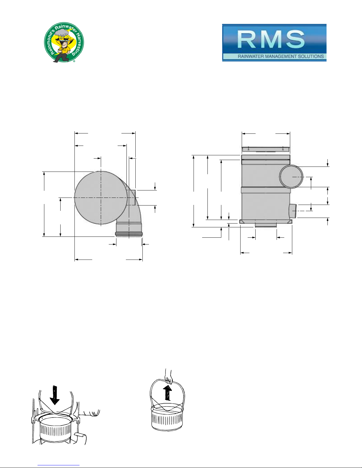
Insert the housing of the RH9521-12 into the open elbow through the opening in the stainless steel
base plate. It is critical that the vertical pressure of the RH9521-12 housing is absorbed completely by
the base plate. If any of the weight is not distributed properly, ad ustments to the base plate will be
necessary.
Rotate the rainwater inlet to the required direction to meet the incoming trunk line from the
downspouts. Rotate the clean water outlet to the required direction to connect to the tank.
Remove the pipe inlet protector from the rainwater inlet on the filter by removing the rubber seal ring
from the inlet bushing. Push the inlet protector out from the inside and replace the rubber seal ring in
the inlet bushing. Make the connection from the trunk line to the filter using a minimum of 40" of
horizontal 12" pipe to reduce the velocity of flow and calm the water to maximize efficiency. The 8"
inlet pipe to the tank should be attached to the clean water outlet on the filter and the inlet of the tank
using a minimum 1/8" fall per linear foot to ensure gravitational flow to the tank.
Once all connections are made and the filter has been checked to ensure it is level and plumb,
backfill the filter using gravel or wet sand.
If the top of the filter housing is below grade, an extension can be added to the filter. The child
protection plate must be removed from the ring and moved to the top ring once installed. The
extension is then placed in the ring on the top of the filter and secured using stainless steel screws
with washers and nuts. An additional top ring will be necessary to support the top of the extension
and receive the child protection plate and lid. Once the exact length of the extension is determined,
remove the excess.
Secure the intermediate ring to the top of the extension ring using stainless steel screw with washers
and nuts and attach the child protection plate. The lid can then be placed on the filter and the
remaining backfilling can take place.
Note: Please see the additional installation notes included at the end of this section.
2

Above Ground
Remove the steel or aluminum cover and the internal packin material.
Create a level and stable platform above the stora e tank for which the base plate of the filter can
sit. It is important that the platform is desi ned to ensure the wei ht of the filter is absorbed by the
base plate. Do not hang filter or strap filter. Hanging or strapping the filter could change the shape of
the filter and will reduce filter efficiency and cause filter to malfunction. A safety rail should be
constructed around the platform to provide a safe area to view and maintain the filter.
Connect and divert all downspouts to a 12" trunk line to the vortex filter rainwater inlet of the filter
usin the standard minimum of 1/8" fall per linear foot.
Remove the pipe inlet protector from the rainwater inlet on the filter by removin the rubber seal rin
from the inlet bushin . Push the inlet protector out from the inside and replace the rubber seal rin in
the inlet bushin . Make the connection from the trunk line to the filter usin a minimum of 10' of
horizontal 12" pipe to reduce the velocity of flow and calm the water to maximize efficiency. The 8"
inlet pipe to the tank should be attached to the filtered water outlet on the filter and the inlet of the
tank usin a minimum 1/8" fall per linear foot to ensure ravitational flow to the tank. Connect a 12"
pipe to the bottom openin on the filter to carry the first flush water and debris to rade or storm as
applicable.
Once all connections are made, be sure the filter has been installed level and plumb.
Note: Please see the additional installation notes included at the end of this section.
Additional Installation Notes:
1. Ensure the lid is never obstructed or buried. Access is necessary for maintenance.
2. The vortex filter inlet and outlets rotate to fit installation needs.
3. Lon er filter handles are available for deeper installations.
4. Adequate space (36") above filter lid must be allowed for filter removal.
5. When connectin a smaller inlet pipin , an eccentric pipin connector must be used to
ensure connectin pipe's invert is level.
NOTE: When required, the
use of an eccentric reducer
is required to reduce turbulence.
120"(305 cm) required min.
3

6. Be sure to contact your supplier before deviating from t ese instructions.
7. T e filter s ould never be buried at a dept over 48". If t e filter must be placed below
ground deeper t an 48", it will be necessary to place t e filter in a vault. Placing t e filter
more t an 48" below ground wit out a vault could compromise t e structural integrity of t e
filter ousing.
Top View Side View
Maintenance:
T e ousing of t e RH9521-12 is maintenance-free. It consists of non-corrosive plastic. T e filter
mes is virtually self-cleaning by t e action of water flowing over t e vertical mes . Nevert eless, a
t in film will build up on t e mes over a period of time. Usually t is does not effect t e efficiency of
t e appliance, but we recommend taking out t e filter insert from time to time and spraying any
openings t at ave become clogged from t e inside wit a strong jet of water (garden spray or
ig -pressure cleaner). Cleaning can also e carried out by and using a small brus (not a wire
brus ) and normal dis was ing liquid.
Removing The Filter:
• Lower t e filter andle onto t e top of t e
filter, position t e flat part under t e lugs
and lift t e filter out.
• Do not leave t e filter andle attac ed after
use. It will impede t e water flow and lower
t e efficiency of t e filter.
11 3/4"
(300) DIA
16 1/8"
(410)
7 7/8"
(200) DIA
35 7/8" (913)
31 7/8" (810)
28" (710) DIA
34 3/4"
(880)
20 3/4"
(525)
7 7/8"
(200) DIA
30 1/2" (776)
SQ Base Plate
11 3/4"
(300) DIA
4 1/4"
(110) 2 1/4"
(56)
28 1/4"
(719) DIA
45 15/16"
(1067)
37 11/16"
(957)
34 7/8"
(884)
20"
(510)
11 3/4"
(300)
DIA
4

Accessories:
Extension pipes are a ailable for the installation of the RH9521-12. These raise the inspection
opening to ground le el. They are fitted onto the final ring, which then acts as an intermediate ring.
The extension pipes are fitted with a final ring on one side to pro ide for the insertion of the manhole
co er and make pa ing around the co er possible.
Components:
1 Cover
2 Filter
3 Lifting Lug
4 Opening
5 Locating Ring for lid
or extension tube
6 Upper Housing
7 Housing Ring
8 Rainwater Inlet
9 Lower Housing
10 Filtered water Outlet
11 Waste water Outlet
12 Deflecting ribs
13 Stream in level
14 Clean water collection ring
15 Inlet seal
16 Filter element seal
17 Steel baseplate
18 Filter lifting handle
19 Extension tube (accessory)
19
5
3
6
7
9
17
12
13
2
1
4
8
15
16
14
10
11
4 5
18
5

Damage in transit
Products are carefully checked before shipping, but the risk
of damage during transport cannot be guaranteed.
• Check the goods for content and damage on receipt.
• Any damage is the responsibility of the carrier, register any
claim with them immediately.
• Contact your supplier before returning any goods.
JAY R.
SMITH MFG. CO.
®
MEMBER OF MORRIS GROUP INTERNATIONAL
POST OFFICE BOX 3237
MONTGOMERY, ALABAMA 36109-0237 (USA)
TEL: 334-277-8520 FAX: 334-272-7396 www.jrsmith.com
CUSTOMER
DRIVEN
SMITH
®
MEMBER OF:
®
ASPE
®
S
A
N
I
T
A
R
Y
E
N
G
I
N
E
E
R
I
N
G
P
r
e
v
e
n
t
i
o
n
R
a
t
h
e
r
T
h
a
n
C
u
r
e
SINCE 1926
PM 1204 D
WARNING: Cancer and Reproductive Harm - www.P65Warnings.ca.gov
Table of contents
Other Vortex Water Filtration System manuals
Popular Water Filtration System manuals by other brands

Doughboy
Doughboy Media Master 1600 owner's guide

Thermo Scientific
Thermo Scientific Barnstead Smart2Pure operating instructions

Watts
Watts Hydro-Safe Steam Max-S1 Installation, operation and maintenance manual

INOXPA
INOXPA 83700 Installation, service and maintenance instructions

GOK
GOK 13512 Series Installation and operating manual

Du Pont
Du Pont WFPT200 installation instructions