Vortex W2W Series User manual

Controls User Manual
Water-to-Water Heat Pump
W2W-series
with electronic controller
Basic Version
iStat6 Control

W2W Heat Pump Controller - Basic
Page 2 of 7 rev 1505
Table of Contents
Controller Basics..............................................................................................................3
Controller Keypad ............................................................................................................4
USER MODE ...................................................................................................................4
ADMIN MODE..................................................................................................................4
Heat Pump Operation ......................................................................................................4
Desuperheater..............................................................................................................5
Freeze Protection.............................................................................................................5
Alarm Conditions and Lockout .........................................................................................5
Controller Wiring Detail....................................................................................................6
Control Parameters – User and Admin Mode ..................................................................7

W2W Heat Pump Controller - Basic
Page 3 of 7 rev 1505
This document describes usage and operation of the controller for the Vortex Water-to-
Water (W2W) heat pump. It is recommended that the installing contractor read through
this short manual in order to become familiar with the correct system setup procedure, and
to take advantage of the various features available. The basic program uses standard Y
and O inputs to operate the heat pump. Vortex also sells heat pumps with advanced
control features which measure storage tanks directly and can utilize outdoor reset to
adjust water temepratures.
Controller Basics
The controller operates the heat pump compressor, refrigerant valves, and system pumps.
Through its LCD display and keypad, important system parameters may be configured and
operating conditions may be monitored.
When the controller keypad has not been pressed for a few minutes, the backlight will turn
off and the display may go blank. Simply press any one of the buttons to wake up the
controller. By default, the controller will display a short message describing the operating
status of the system. Table 1 provides a list of the different possible status messages and
their meaning. There are also a number of small icons that may appear around the edges
of the display according to the current operating status. Table 2 below gives an
explanation of the different icons.
Table 1 - status messages
Message
Meaning
READY No thermostat calls, but system is ready
DELAY Compressor call delayed to prevent short-cycling
NORMAL Heat pump operating normally
FRZ SRC Source-side water is below freeze protection setpoint, compressor stopped
FRZ LD Load-side water is below freeze protection setpoint, compressor stopped
REF PRES Refrigerant high or low pressure switch activated, compressor stopped
LOCK-OUT System has been locked due to recurring alarm conditions, call for service.
Table 2 - display icons
Icon Meaning
Flame Compressor call at Y1_IN
Snowflake Cooling signal at O_IN
Sun Desuperheater pump on

W2W Heat Pump Controller - Basic
Page 4 of 7 rev 1505
Controller Keypad
By using the option and setting keys, different parameters and their settings may be
displayed and modified. Use the option key to scroll through the available parameters,
and use the setting key to modify the parameter’s current setting (if available). By default,
the control will remain in ‘user’ mode, in which a limited selection of parameters may be
accessed. By entering ‘admin’ mode, additional parameters may be made available.
Please exercise caution while in ‘admin’ mode, as these settings are meant to be
accessed by the experienced user or installing contractor. A description of each of the
modes is found below.
USER MODE
This is the basic display and operating mode, in which only a limited selection of
parameters may be accessed and modified. Refer to Table 3 for description of each item
displayed.
ADMIN MODE
This is the advanced display and configuration mode. It is intended only for the properly
trained contractor. To enter ‘admin’ mode, press any button to illuminate the display
backlight, then press and hold the two option buttons at the same time (‘user’ will be
displayed at first, hold until ‘admin’ is displayed). You can now scroll through the display
items by using the lower two option buttons, and adjust certain values using the upper two
setting buttons. To return the control to ‘user’ mode simply wait a few minutes or press
and hold both option buttons. Use Table 4 as a quick reference on the items available in
this mode. Detailed descriptions on important parameters are found below.
Heat Pump Operation
There following parameters may be useful in system commissioning and troubleshooting.
OFF_MIN (default is 5 minutes) – The anti short-cycle delay setting. The counter will
begin at the end of a heating or cooling call, or upon initial unit power-up.
COMP_AUTO (default=ON) – “Automatic” compressor mode - set this to OFF to prevent
the compressor from running. This may be useful in basic system troubleshooting. Be
sure to set back to ON when done to allow the system to operate normally.
# Cycles – Counts the number of heating & cooling cycles that have occurred. This may
be useful in determining the operation history of a heat pump.
Run hrs – Counts the total elapsed time that the heat pump has run, in hours. This may
be useful in determining the operation history of a heat pump.
SRC_TMP – The measured source-side leaving water temperature, in degrees
Fahrenheit.

W2W Heat Pump Controller - Basic
Page 5 of 7 rev 1505
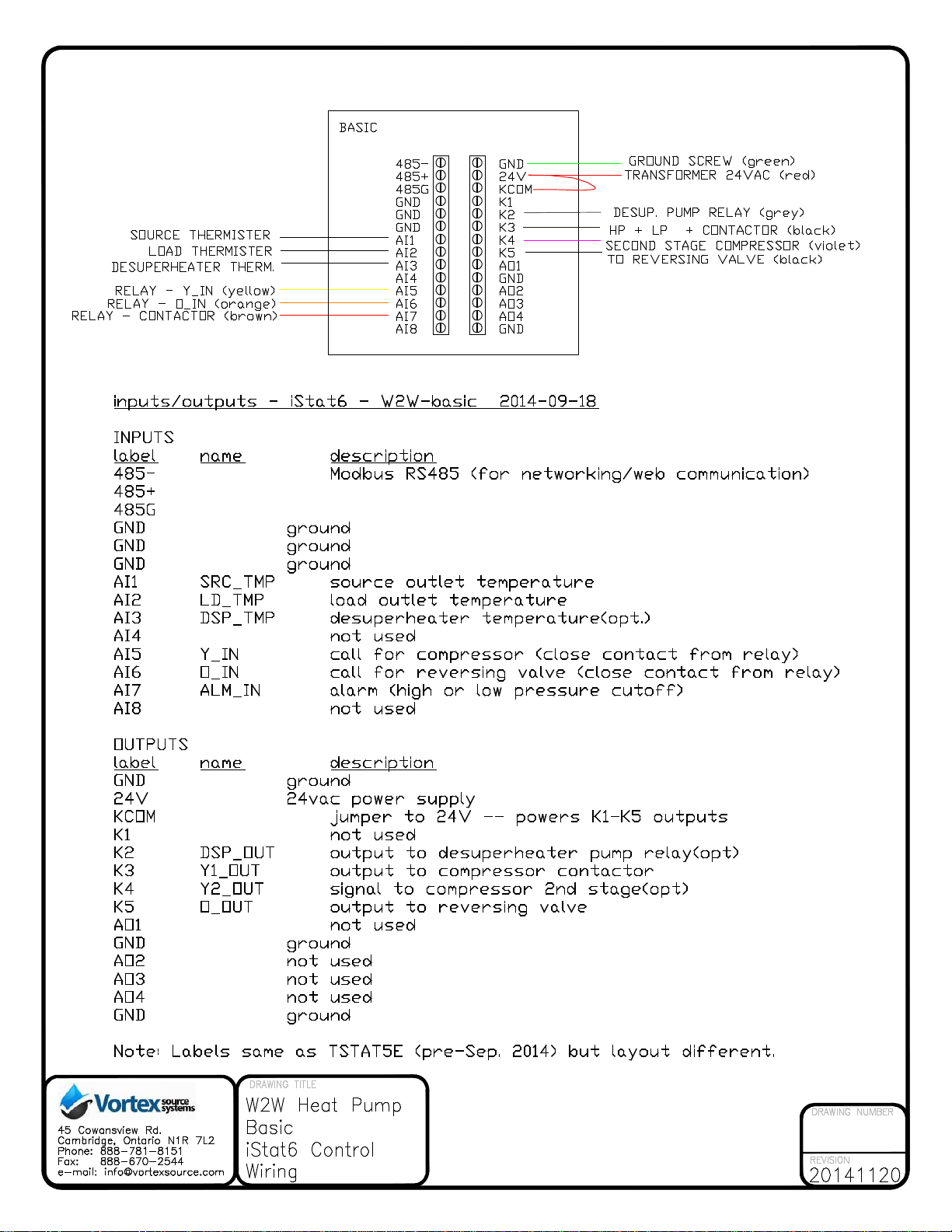
LD_TMP – The measured load-side leaving water temperature, in degrees Fahrenheit.
Desuperheater
For W2W heat pumps equipped with an optional desuperheater (hot water booster), the
following parameters apply:
DSP_TMP – The measured desuperheater temperature, in degrees Fahrenheit.
DSP_MAX (default is 140oF) – Maximum allowable desuperheater temperature. When the
measured temperature exceeds this setting, the desuperheater pump will not be brought
on.
Freeze Protection
The W2W heat pump controller measures the source- and load-side leaving water
temperatures to help prevent the system from freezing. By default, the freeze protection
level is set based on water. If an antifreeze solution is used, these levels may need to be
changed to match that of the true freezing point of the solution. The parameters below are
used to modify freeze protection settings:
LD Min &SRC Min (default is 34oF) – the minimum allowable load and source leaving
water temperatures. If the measured temperature drops below this setting, the
compressor will be shut off. This value should be set slightly above the freeze point of the
water or antifreeze solution used in the source/load loop.
Alarm Conditions and Lockout
There are a number of possible operating conditions which can result in a system alarm,
causing the call to the compressor to be interrupted. When an alarm occurs, a short status
message will be displayed, as outlined in Table 1 on page 3 of this manual. If three alarm
conditions occur within 24 hours of one another, the system controls will “lock out” and no
longer allow the heat pump to run. If this occurs, there may be an issue with the heat
pump, and so a qualified technician should be contacted for service.
LOCK-OUT – The system has locked out due to a recurring alarm condition. Contact a
qualified technician for service. Qualified technicians may reset alarms and lockouts using
the parameters below:
LAST_TXT – will display the last alarm message that occurred. To reset this, set
LAST_RST to ON for a few seconds, and then set back to OFF. It is important to write
this down before resetting, in order to help with system troubleshooting.
ALM_CTR – will count the number of alarm conditions encountered over the last 24 hours.
If the alarm counter reaches three, the system will be locked out. To reset the alarm

W2W Heat Pump Controller - Basic
Page 6 of 7 rev 1505
counter, set ALM_RST to ON for a few seconds and then set back to OFF. Compressor
should then be allowed to come back on once the delay period has passed.
Controller Wiring Detail
The controller diagram below shows the wire connections to the control mounting plate.
Depending on the model of W2W heat pump, some connections may not be used.
To remove the control, use a small Phillips screwdriver to loosen the screen on the bottom
of the control. The control pulls out from the bottom.

W2W Heat Pump Controller - Basic
Rev_Q06 Page 7 of 7
Control Parameters – User and Admin Mode
Table 3 - User Mode Parameters
Line 1 Line 2 Set.*Description Notes
Status #### D Displays status text.
LAST_ERR #### D Displays last fault text.
SRC_TMP ###.# F D Source (Ground) heat exchanger outlet water temperature
LD_TMP ###.# F D Load (Tank) heat exchanger outlet water temperature
# Cycles #### D Counts the # of compressor on cycles (lifetime)
Run hrs #### D Counts number of hours of compressor run time.
W2W Basic ##.## D Program name Default setting is 1
* Note: “D” in the set column indicates this parameter is for display only, and cannot be modified using the controller.
Table 4 – Admin Mode Parameters
Line 1 Line 2 Set.*Description Notes
ALM_RST (0)Off/(1)On Manual reset of alarm counter. Default setting is 0
LAST_ERR #### D Displays last fault text.
LAST_RST (0)Off/(1)On Manual reset of last fault. Default setting is 0
SRC_TMP ###.# F D Source (Ground) heat exchanger outlet water temperature
LD_TMP ###.# F D Load (Tank) heat exchanger outlet water temperature
DSP_TMP ###.# F D Desuperheater water temperature
DSP_MAX #### F Maximum allowed desuperheater water temperature. Default setting is 140
DSP_DB #### F Thermostat deadband for desuperheater pump. Default setting is 10
SRC Min #### F Source HX outlet minimum allowed water temperature Default setting is 34
LD Min #### F Load HX outlet minimum allowed water temperature Default setting is 34
OFF_MIN #### m Time in minutes between compressor cycles. Default setting is 5
# Cycles #### D Counts the # of compressor on cycles (lifetime)
Run hrs #### h D Counts number of hours of compressor run time.
COMP_AUTO (0)Off/(1)On Compressor in "auto" mode. Turn off to lock out compressor for testing. Default setting is ON
W2W Basic ##.## D Program name Default setting is 1
Modbus #### Modbus address Default setting is 123
* Note: “D” in the set column indicates this parameter is for display only, and cannot be modified using the controller.

Table of contents
Other Vortex Water Pump manuals

Vortex
Vortex HZ 401 Operating and maintenance manual

Vortex
Vortex BWO 155 User manual

Vortex
Vortex CDX2532G User manual

Vortex
Vortex BW 152 User manual

Vortex
Vortex BLUEONE BWO 155 User manual

Vortex
Vortex BW-SL 154 User manual

Vortex
Vortex BlueOne BWO 155 SL User manual

Vortex
Vortex B series User manual

Vortex
Vortex BW 152 User manual

Vortex
Vortex BLUEONE BWO 155 User manual
Popular Water Pump manuals by other brands

SkyLink
SkyLink SK80 Operation and maintenance manual

Edson
Edson 120A Operation manual

Giant
Giant P200 Series Operating instructions/ repair and service manual

Pentair
Pentair Berkeley 10VT Series Installation, operation and maintenance manual

SKC
SKC Pocket Pump TOUCH operating instructions

PeriBest Pumps
PeriBest Pumps I12 manual