manuals.online logo
Brands
  1. Home
  2. •
  3. Brands
  4. •
  5. Vortice
  6. •
  7. Fan
  8. •
  9. Vortice LINEO 100 QUIET User manual

Vortice LINEO 100 QUIET User manual

COD. COD. 5.671.084.018 10/12/2021
Libretto istruzioni
Instruction booklet
Notice d’emploi et d’entretien
Betriebsanleitung
Manual de instrucciones
Instructieboekje
Bruksanvisning
Käyttöohjeet
Manual de instrucţiuni
Инструкция по эксплуатации
Návod na používanie
LINEO 200 QUIET ES
LINEO 100 QUIET ES
LINEO 125 QUIET ES
LINEO 150 QUIET ES
LINEO 160 QUIET ES
11
Product description
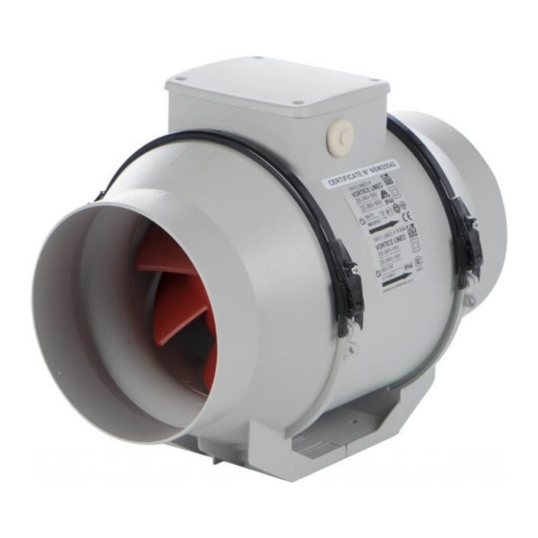
The appliance you have purchased is a silenced in-line centrifugal extractor fan designed to expel air through a
ventilation duct.The product is made of an outer shell in thermoplastic material co-molded with the polyurethane
soundproofing part, the other parts of the product are made of thermoplastic resin. It has an electronically
controlled two-speed brushless motor with maximum and minimum speed settings.
Compliance
• These appliances are designed for use in residential and
commercial properties.
• This appliance can be used by children aged from 8 years and above
and persons with reduced physical, sensory or mental capabilities or
lack of experience and knowledge if they have been given
supervision or instruction concerning use of the appliance in a safe
way and understand the hazards involved. Children shall not play
with the appliance. Cleaning and user maintenance shall not be
made by children without supervision.
• The appliance must be installed by a professionally qualified
electrician.
•The electrical system to which the product is connected must be in
compliance with applicable regulations.
•An omnipolar switch with a contact opening distance of 3 mm or
higher should be provided for installation, enabling complete
disconnection under overvoltage category III conditions.
•Products equipped with single-phase wiring (M) engines ALWAYS
require connection to 220-240V (or only 230V where required)
single-phase lines. Any kind of modication shall be considered as
product tampering and shall nullify the relative warranty.
• The control accessories must be installed in premises with a room
temperature that does not exceed 25°C.
Duct and window - wall fan units
Precautions must be taken to prevent gas coming from the gas flue
pipe or from other fuel combustion units from entering into the room.
ENGLISH
!
12
Safety/warnings
ENGLISH
• Do not use this appliance for functions other thant hose described in this instruction booklet.
• After removing the appliance from its packaging, ensure that it is complete and undamaged.
If in doubt contact a professionally qualified electricianor VORTICE*. Do not leave packaging within the reach
of children or infirm persons.
• Certain fundamental rules must be observed when using any electrical appliance, including:
a) do not touch it with wet or damp hands;
b) do not touch it while barefoot.
• If you decide to stop using the appliance, switch it off and disconnect it from the power supply, storing it out of
reach of children and infirm persons
• Do not operate the appliance in the presence of inflammable vapours (alcohol, insecticides, petrol,etc.)
• Do not sit or place objects on or in the appliance.
Warning:this symbol indicates precautions that must be taken to avoid injury
•Do not make modifications of any kind to this appliance.
•Do not expose this appliance to the weather (rain, sun, etc.).
•The inside of the appliance should be cleaned only by qualified personnel (fig. 24).
•Do not immerse the appliance or any parts of it in water or other liquids. Refer to the relevant instructions to
clean the appliance (fig. 23-25).
•Regularly inspect the appliance for visible defects. If any are found, do not operate the appliance and contact
VORTICE* immediately.
•If the appliance does not function correctly or develops a fault, contact VORTICE* immediately and ensure that
only original VORTICE spares are used for any repairs.
•Should the appliance be dropped or suffer a heavy blow, have it checked immediately by VORTICE*.
•The appliance is double insulated and therefore does not need to be earthed.
•The electrical power supply / socket to which the appliance is to be connected must be able to provide the
maximum electrical power required by the appliance. If it cannot do this, contact an electrician to make the
necessary modifications.
•Switch off the appliance at the installation's main switch: a) if the appliance does not function correctly; b)
before cleaning the outside of the appliance; c) if the appliance is not going to be used for any length of time.
•The appliance cannot be used to control activation of water heaters, room heaters, etc. and it must not exhaust
into the hot air flues of such appliances.
•The room must have an adequate source of replacement air for this appliance to function effectively. Moreover,
if there is any non-sealed combustion based appliance such as a water heater, gas stove, etc. in the same
room, air replacement must be sufficient for all appliances to work effectively together.
•The appliance must discharge into a single duct (dedicated to this product).
•Keep the appliance’s inlet and outlet grilles free to ensure an optimum flow of air.
•The appliance’s outlet and inlet ports must always be connected to a suitable duct (fig. 2).
•The maximum environment temperature for appliance operation is 60°C, with the exception of
model 200 for which it is instead 50°C.
• Specifications for the power supply must correspond to the electrical data on data plate A (fig.3)
•This symbol means that the operation must be performed by professionally qualified personnel.
N.B.
• All versions of 100-125-150-160-200 appliances are fitted with a safety overtemperature device.
• (Fig. 13.1) LINEO 100 QUIET ES and LINEO 150 QUIET ES are provided with two fittings that allow to
reduce the product diameter (inlet and outlet side) respectively from 125 to 100 mm and from 160 to
150 mm.
*(or an authorized VORTICE dealer if you are outside the UK-Ireland territory).
Caution: this symbol indicates precautions that must be taken to avoid damaging the
appliance
!
Typical applications
LINEO (100-125-150-160) QUIET ES: fig. 1-2.
LINEO (200) QUIET ES: fig. 1.1-2.1.
Installation
Fig. 3 ÷ 22.
Fig.3: B=Inlet; C= Outlet.
Wiring diagram
Fig. 18 ÷ 22.
Initial configuration
The installer must configure appliance operation by following the steps described later on.
Selecting the product model: see below. This step is carried out in the factory; the instructions provided in this
booklet may only be of use if it becomes necessary to reset the status following accidental tampering with the
dip-switch.
Selecting the operating mode: see below. There are two modes: with two speeds V1 and V2, which can be
selected via an external switch, or with speed that can be adjusted via an external potentiometer.
Setting the V1 and V2 values (for two-speed operating mode).
Selecting the product model
The model is selected by setting the dip-switch 1 indicated in the figure as described in the table below.
13
ENGLISH
Model SW1
Int. 1 Int. 2 Int. 3 Int. 4
LINEO 100 QUIET ES /
LINEO 125 QUIET ES OFF OFF OFF ON
LINEO 150 QUIET ES /
LINEO 160 QUIET ES OFF OFF ON OFF
LINEO 200 QUIET ES OFF ON OFF ON
ON
1 2 3 4
OFF
DIPSWITCH
12
SW 1 : MODEL
SW 2 : SETUP
TRIMMER
LINEO (100 --> 200) QUIET ES
Selecting the operating mode
Setting the V1 and V2 values
The appliance leaves the factory with default nominal settings V1=VMIN, V2=VMAX
Values V1 and V2 can be adjusted as follows:
Two-speed mode:
cut off the power supply
set the dip-switch SW2 indicated in the figure:
Int.2=ON; Int.3=OFF; Int.4=OFF
ON
1 2 3 4
OFF
Adjustable speed mode:
cut off the power supply
set the dip-switch SW2 indicated in the figure:
Int.2=OFF; Int.3=OFF; Int.4=OFF
ON
1 2 3 4
OFF
14
ENGLISH
Isolate the power
To set the trickle and boost variable speeds.
Set the SW2 dip-switch as follows:
1 to off, 2 to off, 3 to off, & 4 to on
ON
1 2 3 4
OFF
When the power is switched on, the trickle speed (V1) runs at the
factory default speed.
The trickle / default speed (V1) can be adjusted to the desired flow
rate using the potentiometer.
A small flat head screw driver will be required.
The trickle (V1) speed should set 100 rpm lower than the desired
boost (V2)
The trickle speed value can now be saved by switching 1 to on.
The boost (V2 default) can now be adjusted
using the potentiometer.
ON
1 2 3 4
OFF
Once the desire boost flow rate is achieved it can be set
by switching 1 to off.
ON
1 2 3 4
OFF
Isolate the power
To complete the commissioning and prevent tampering
set 1, 2, 3 & 4 to off
ON
1 2 3 4
OFF
Restoring nominal values
If necessary, the nominal factory-set values for V1 and V2 can be restored using the following procedure:
Operation
Depending on the mode selected during installation:
-two-speed mode: the appliance operates continuously; two speeds V1 and V2 can be selected using an
external switch
-adjustable speed mode: the appliance can operate at a speed which is adjusted between Vmin and Vmax
(via an external potentiometer). The VORTICE ON/OFF control box + potentiometer (code 12826 / 12828, on
request) can also be used.
Maintenance and cleaning
Fig. 23 ÷ 25.
Cut off the power supply
Set the dip-switch SW2 indicated in the figure: Int.3=ON
ON
1 2 3 4
OFF
Restore the power supply:
V1 and V2 are automatically restored to the nominal factory-
set values corresponding to the selected model, as described above.
The restoring of nominal values is indicated by two quick flashes of an
LED on the card.The motor is deactivated automatically
Cut off the power supply
Reset the dip-switch SW2 indicated in the figure: Int.3=OFF
ON
1 2 3 4
OFF
15
ENGLISH
Disposal
This product complies with Directive 2012/19/EU on the management of waste electrical and electronic
equipment (WEEE).
The crossed-out wheeled bin symbol on the appliance indicates that, at the end of its life, the
product should not be discarded together with household waste but must be taken to a separate
collection point for electrical and electronic equipment. This will avoid negative effects on the
environment and health, and will encourage correct treatment, disposal and recycling of the
materials from which the product is made.
Contact the municipal authority for the location of this type of facility. Alternatively, the distributor is obliged to
take back the appliance to be disposed of free of charge in exchange for the purchase of an equivalent
appliance.
16
ENGLISH
Technical specification
PRODUCT V Hz
Power
(10V/8V/
6V/ 4V)
[W]
Airflow
(10V/8V/
6V/ 4V)
[m3/h]
Pressure
(10V/8V/
6V/ 4V)
[mmH2O]
RPM
(10V/8V/
6V/ 4V)
Sound
pressure level
[LpA [db(A)] 3m
-IRRADIATED-
(10V/8V/
6V/ 4V)
INSULATION
CLASS
Max room
temperature [°C]
LINEO 100
QUIET ES 220-240 50-60 23 - 14,7
8,3 - 6,2
300 - 250
175 - 135
24,8 - 11,4
5,8 - 3,5
2510 - 2050
1450 - 1140
30,9 - 24,8
15,9 - 9,9 II 60
LINEO 125
QUIET ES 220-240 50-60 24 - 16
8,8 - 6,6
380 - 320
225 - 180
23,7 - 11
5,6 - 3,3
2210 - 1865
1340 - 1080
28,7 - 25,1
16,4 - 11,3 II 60
LINEO 150
QUIET ES 220-240 50-60 31 - 20
10,6 - 7,7
515 - 430
305 - 250
24,2 - 14,7
7,5 - 4,6
2030 - 1700
1240 - 1015
31 - 26
18,6 - 13,7 II 60
LINEO 160
QUIET ES 220-240 50-60 31 -19,7
10,6 - 7,7
525 - 435
315 - 250
23,9 - 14,4
7,5 - 4,5
2035 - 1685
1245 - 1010
29,2 - 24,7
17,4 - 12,5 II 60
LINEO 200
QUIET ES 220-240 50-60 88 - 52,4
25,3 -15,2
1145 - 945
720 - 570
33,6 - 22,9
13,9 - 8,6
2700 - 2245
1705 - 1380
35,8 - 30,9
24,8 - 19,7 II 50
LINEO (100 - 125 - 150 - 160) QUIET ES
71
2
FIGURE
APPLICAZIONI TIPICHE
LINEO (100 - 125 - 150 - 160) QUIET ES
1
FIGURES
FIGURES
ABBILDUNGEN
FIGURAS
AFBEELDING
FIGURER
KUVAT
FIGURI
OBRÁZOK
TYPICAL APPLICATIONS
APPLICATIONS TYPIQUES
TYPISCHE ANWENDUNGSARTEN
APLICACIONES TÍPICAS
TOEPASSINGEN
TYPISKA ANVÄNDNINGSOMRÅDEN
ASENNUSESIMERKIT
APLICAțII TIPICE
ТИПИЧНЫЕ ОБЛАСТИ ПРИМЕНЕНИЯ
TYPICKÉ APLIKÁCIE
LINEO (200) QUIET ES
LINEO 200 QUIET ES
72
1.1
2.1
Huomio:
FI
73
Attenzione:la bocca di mandata del prodotto deve sempre essere collegata a
un condotto.
Caution:the appliance's outlet port must always be connected to a
suitable duct.
Attention :la bouche de refoulement du produit doit toujours être reliée à un
conduit.
Achtung:der Luftauslass des Geräts muss stets an einen Kanal
angeschlossen sein.
Atención:la boca de expulsión del producto debe estar siempre conectada
a un conducto.
IT
EN
FR
DE
ES
la bocca di mandata e aspirazione del prodotto deve sempre essere
collegata a un condotto (fig. 2).
the appliance’s outlet and inlet ports must always be connected to a
suitable duct (fig. 2). .
La bouche d'arrivée et d'aspiration du produit doit toujours être reliée
à un conduit (fig. 2). .
Die Auslass- und Einlassöffnungen des Geräts müssen immer an
einen geeigneten Kanal angeschlossen werden (Abb. 2).
La boca de salida y de aspiración del producto siempre deberá
conectarse a un conducto (fig. 2). .
De uitgangs- en ingangspoorten moeten altijd op een geschikte
leiding zijn aangesloten (Afb. 2).
Apparatens utgångar och ingångar ska alltid vara kopplade till en
lämplig ledning (fig. 2).
Laitteen lähtö- ja tuloportit tulee aina liittää asianmukaiseen
kanavaan (Kuva 2).
Orificiul de evacuare şi aspiraţie a produsului trebuie să fie
întotdeauna conectat la o conductă (fig. 2).
Выходные ивходные отверстия прибора всегда должны быть
подключены кподходящему воздуховоду (Рис. 2).
Let op:
Varning:
NL
SV
Huomio:
FI
Aten∑ie:
RO
Внимание:
RU
Prívodný a sací otvor výrobku musí byťvždy napojený na potrubie
(obr. 2).
SK
Pozor
:
LINEO (100 - 125 - 150 - 160) QUIET ES
LINEO (200) QUIET ES
74
INSTALLAZIONE
3
INSTALLAZIONE
INSTALLATION
INSTALLATION
INSTALLATION
INSTALACIÓN
INSTALLATIE
INSTALLATION
ASENNUS
INSTALARE
УСТАНОВКА
POSTAVLJANJE
75
4
12
5
67
LINEO (100 - 125 - 150 - 160) QUIET ES
76
8
LINEO QUIET
100
125
150
160
6 mm
11
9
10
77
2
1
12
13
(LINEO 100 QUIET ES /
LINEO 150 QUIET ES )
13.1
78
LINEO (200) QUIET ES
4A
12
5A
6A 7A
LINEO QUIET ES
200
8 mm
79
8A 9A
10A
11A
80
2
1
12A
13A
LINEO 100 QUIET ES
Ø14 mm Ø16 mm
81
14 15
16
17
LINEO (100 —> 200) QUIET ES
12 POLES SWITCH (DPST)
1
2
2
4
4
3ON/OFF SWITCH (SPST)
DRY CONTACT FOR
ALARM SIGNALLING
(250VAC, max current 3A)
POTENTIOMETER
(FROM 5 KOHM TO 10 KOHM) 3
PCB/SCHEDA
PCB Control Port Description
---------------------------------------
P0 = Potentiometer 0V = GND
PI = Potentiometer Input Signal = 0-10V
P10 = Potentiometer 10V = +10V
S1-S2 = dry contact for MAX/MIN speed
R1-R2 = dry contact for optional Alarm
WIRING TO AN EXTERNAL STANDARD POTENTIOMETER /
COLLEGAMENTO CON POTENZIOMETRO ESTERNO STANDARD
N
N
L
L
P0
PI
P10
S1
R1
R2
S2
LINEO (100-125-150-160-200) QUIET ES
82
SCHEMI PER COLLEGAMENTO ELETTRICO
18
WIRING DIAGRAM
SCHÉMAS POUR LE BRANCHEMENT ÉLECTRIQUE
SCHALTPLAN FÜR DEN ELEKTRISCHEN ANSCHLUSS
ESQUEMAS DE CONEXIÓN ELÉCTRICA
SCHEMA’S VOOR ELEKTRISCHE AANSLUITING
KOPPLINGSSCHEMAN
SÄHKÖKAAVIOT
SCHEME PENTRU CONECTAREA ELECTRICĂ
СХЕМЫ ЭЛЕКТРИЧЕСКИХ СОЕДИНЕНИЙ
SCHÉMA ZAPOJENIA
PCB/SCHEDA
PCB Control Port Description
---------------------------------------
P0 = Potentiometer 0V = GND
PI = Potentiometer Input Signal = 0-10V
P10 = Potentiometer 10V = +10V
S1-S2 = dry contact for MAX/MIN speed
R1-R2 = dry contact for optional Alarm
WIRING TO THE “POTENTIOMETER” + ON/OFF” CONTROL BOX TYPE 503 (CODE 12826)
COLLEGAMENTO ALLA SCATOLA COMANDI TIPO 503 CON POTENZIOMETRO E TASTO ON/OFF (CODICE 12826)
LINEO (100-125-150-160-200) QUIET ES
12 POLES SWITCH (DPST)
2DRY CONTACT FOR
ALARM SIGNALLING
(250VAC, max current 3A)
1L
N
2
CONTROL BOX
/ SCATOLA COMANDI
NLN1L1S3S2S1SCBCBNOBNC
P0
PI
P10
S1
S2
R2
R1
NL
SURFACE MOUNTING
or FLUSH TYPE 503 / MONTAGGIO
A PARETE oppure A INCASSO 503
12 POLES SWITCH (DPST)
2
3
LOW/HIGH SPEED SWITCH
SPST
DRY CONTACT FOR
ALARM SIGNALLING
(250VAC, max current 3A)
1
L
N
2
3
MIN
MAX
P0
PI
P10
S1
S2
R2
R1
PCB/SCHEDA
PCB Control Port Description
---------------------------------------
P0 = Potentiometer 0V = GND
PI = Potentiometer Input Signal = 0-10V
P10 = Potentiometer 10V = +10V
S1-S2 = dry contact for MAX/MIN speed
R1-R2 = dry contact for optional Alarm
WIRING TO AN EXTERNAL LOW/ HIGH SPEED SWITCH /
COLLEGAMENTO A INT. ESTERNO PER MAX E MIN.VELOCITÀ
NL
LINEO (100-125-150-160-200) QUIET ES
83
19
20

Other manuals for LINEO 100 QUIET

3

This manual suits for next models

4

Other Vortice Fan manuals

Vortice Ariett I User manual

Vortice

Vortice Ariett I User manual

Vortice TIRACAMINO TC 10 M User manual

Vortice

Vortice TIRACAMINO TC 10 M User manual

Vortice Nordik Design 1S User manual

Vortice

Vortice Nordik Design 1S User manual

Vortice VORT PRESS 110 LL User manual

Vortice

Vortice VORT PRESS 110 LL User manual

Vortice AXIAL K User manual

Vortice

Vortice AXIAL K User manual

Vortice CA ES Series User manual

Vortice

Vortice CA ES Series User manual

Vortice VORT NRG EVO 005 User manual

Vortice

Vortice VORT NRG EVO 005 User manual

Vortice VORTICEL E User manual

Vortice

Vortice VORTICEL E User manual

Vortice VORT MAX S User manual

Vortice

Vortice VORT MAX S User manual

Vortice VORT PRESS HABITAT 45/135 LL User manual

Vortice

Vortice VORT PRESS HABITAT 45/135 LL User manual

Vortice NORDIK HVLS SUPER BLADE E User manual

Vortice

Vortice NORDIK HVLS SUPER BLADE E User manual

Vortice LINEO 100 QUIET User manual

Vortice

Vortice LINEO 100 QUIET User manual

Vortice VORT QUADRO MICRO 80 User manual

Vortice

Vortice VORT QUADRO MICRO 80 User manual

Vortice VORTICE LINEO V0 User manual

Vortice

Vortice VORTICE LINEO V0 User manual

Vortice PENTA ES EP User manual

Vortice

Vortice PENTA ES EP User manual

Vortice HRI-E ONE User manual

Vortice

Vortice HRI-E ONE User manual

Vortice CA-V0 User manual

Vortice

Vortice CA-V0 User manual

Vortice NORDIK STORM User manual

Vortice

Vortice NORDIK STORM User manual

Vortice RXC/Hi Series User manual

Vortice

Vortice RXC/Hi Series User manual

Vortice Caldopro Plus User manual

Vortice

Vortice Caldopro Plus User manual

Vortice BRA.VO Qe User manual

Vortice

Vortice BRA.VO Qe User manual

Vortice CA V0 E User manual

Vortice

Vortice CA V0 E User manual

Vortice LINEO 100 QUIET User manual

Vortice

Vortice LINEO 100 QUIET User manual

Vortice LINEO 250 ES User manual

Vortice

Vortice LINEO 250 ES User manual

Popular Fan manuals by other brands

Titon CME3 Q Plus A product manual

Titon

Titon CME3 Q Plus A product manual

Ruck Ventilatoren DVA EC30 Series Assembly instruction

Ruck Ventilatoren

Ruck Ventilatoren DVA EC30 Series Assembly instruction

KOBE KPF400 Operator's manual

KOBE

KOBE KPF400 Operator's manual

Hunter 23898 Installation and operation guide

Hunter

Hunter 23898 Installation and operation guide

Beper P206VEN161 User instructions

Beper

Beper P206VEN161 User instructions

Beper P206VEN150 manual

Beper

Beper P206VEN150 manual

Rowenta Essential VF411 Series user guide

Rowenta

Rowenta Essential VF411 Series user guide

Ryobi R18HAC Original instructions

Ryobi

Ryobi R18HAC Original instructions

Modern Forms Slim installation instructions

Modern Forms

Modern Forms Slim installation instructions

Wallair W-Style RE Premium 100 installation manual

Wallair

Wallair W-Style RE Premium 100 installation manual

Fantech FTC-P-18-5 Technical manual

Fantech

Fantech FTC-P-18-5 Technical manual

S&P ARTIC TOWER M Installation manual and operating instructions

S&P

S&P ARTIC TOWER M Installation manual and operating instructions

minkaAire New Era instruction manual

minkaAire

minkaAire New Era instruction manual

OBH Nordica AIRLINE 1381 Instructions of use

OBH Nordica

OBH Nordica AIRLINE 1381 Instructions of use

Excelair EVHF46120M instruction manual

Excelair

Excelair EVHF46120M instruction manual

Somogyi home CMF64 instruction manual

Somogyi

Somogyi home CMF64 instruction manual

Envirovent fliterless infinity fan 230v installation guide

Envirovent

Envirovent fliterless infinity fan 230v installation guide

VENCHA Raven instruction manual

VENCHA

VENCHA Raven instruction manual

manuals.online logo
manuals.online logoBrands
  • About & Mission
  • Contact us
  • Privacy Policy
  • Terms and Conditions

Copyright 2025 Manuals.Online. All Rights Reserved.