Voscom VOS-0800FT/R Series User manual

VOS-0800FT/R series
8-Channel Simplex Audio Transmission
Installation Manual
Fiber Optic Transmission Systems
VOSCOM TECHNOLOGIES CO.,LIMITED
WWW.VOSCOM.COM
TM

Important Safety Instructions EN_1
1. Readthese instructions. Keep these instructions. Heed allwarnings. Follow all instructions.
5. Donot use this apparatus near water. Cleanonly with dry cloth.
7. Donot block any ventilation openings. Install in accordance with the manufacturers
instructions.
8. Donot install near any heat sources such as radiators, heatregisters, stoves,or other
apparatus (includingamplifiers) that produce heat.
9. Donot defeat the safety purpose of the polarized or grounding-type plug. A polarized plug
has twoblades withone wider than the other. Agrounding type plug has two blades and a third
grounding prong. The wideblade or the third prong are provided for your safety. Ifthe provided
plug doesnot fitinto your outlet consult an electrician for replacement of the obsolete outlet.
10. Protectthe power cord from being walked on or pinched particularly at plugs,convenience
receptacles, andthe points where they exit from the apparatus.
13. Referall servicingto qualifiedservice personnel. Servicing is required when the apparatus
has beendamaged in any way, suchas power-supply cord or plug is damaged, liquid has been
spilled or objects havefallen into the apparatus,the apparatushas been exposed to rain or
moisture, doesnot operatenormally,or has been dropped.
14. Apparatusshall not be exposed to dripping or splashing and that no objects filled with liquids,
such asvases shall be placed on the apparatus.
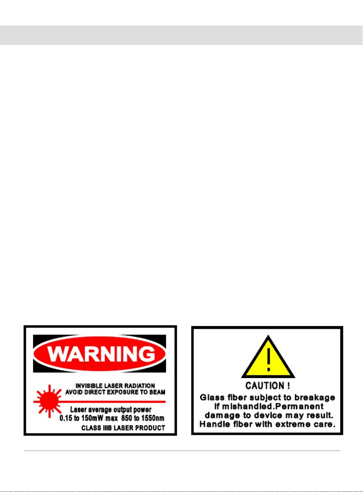
15. WARNING: To reduce the risk of fire or electric shock, do not expose this apparatusto rain or
moisture.
16. Installation should be done only by qualified personnel and conform to all local codes.
20. CAUTION: These servicing instructions arefor useby qualified service personnel only.To
reduce therisk of electric shock do not perform any servicing other than that contained in the
operating instructionsunless youare qualifiedto do so.
Website:www.voscom.com

Product Overview En_2
The VOS-0800FT/R can transmission8-Channel
simplex analog auido oversinglemode or multimode
optical cable.
Stand-alone orrack-mount. The cards can be inserted
into our 14 slots,19inch 4U or 6U rack-mountable
card cage (VOS-CH04 or VOS-CH06).
System Diagram:
Model Number
Transmitter Receiver Fiber Mode Wavelengths Optical
Power
Budget
Maximum
Transmission
Distance
Multi-Mode 1310nmVOS-0800FMRVOS-0800FMT
•The OpticalPower Budgetdata fitMulit-mode(62.5/125 m),Single-Mode(9/125 m).
•When using50/125 m multimode fiber, subtract3 dBfrom the optical power budget.
•Optical transmissiondistance is limited to optical loss of thefiber and any additional loss introduced by connectors,
splices andpatch panels.
•Maximum transmissiondistance is also limited by fiber bandwidth.
•Power adapteris manufactured by thirdparty and is supplied with fitted screw-terminal outputcables.Power
adapter included(for standalone) US, European, UK or Australian powerplug.
•Please feelfree to consult factory for anyspecial requirement and customization
Note:
16dB 2km
Single-Mode
VOS-0800FSRVOS-0800FST 12dB 20km
Models and Optical Power Budget:
•24-Bit Digitally Encoded Audio over onefiber
•Multi-mode Fiber Support for Distances up to 2.0 km
•Single-Mode Fiber Support for Distances up to 100 km
•No EMI or RFI and noground loops
•Stand alone or rack-mount
Features:
Note: More detailspecification please find inthe datasheetor our website: www.voscom.com
Audio
88
1310nm
Microphone
1 Fiber opticCable
Speaker
VOS-0800FT
Transmitter VOS-0800FR
Receiver
8 xAudio 8 xAudio

Panel & Cable Connection En_3
Installation Instructions:
NOTE1: Digital video optic transmitterand receivershould be used in pairs, one is Transmitter
(LED is red), theother is Receiver (LED is green).
FRONT PANEL
FTX
REAR PANEL
DC5V
1 2 3 4 5 6 7 8 1 2 3 4 5 6 7 8 1 2 3 4 5 6 7 8
EXT1 EXT2 EXT3 IP/EXT
12
None
3
1
1
2
3
Fiber Optic Connector, FC/PC or ST/PC
Stand-alone Power supply Connector, DC5V3A Input.
Audio Connector, Terminal Block,analog audio input (Transmitter)/output (Receiver)

Panel & Cable Connection En_4
Transmitter (Audio): 8-Channel Simplex Audio Connection (Input)
NOTE: AUDIO SIGNAL AND IMPEDANCE MODE
1) Audio Signal: The audiois Mono Audio in default, can support Stereo audio, but you
should consultfor us before the order.
2) Impedance Mode: The audio is unbalanced mode in default, can support 600 ohm
balanced audio, but you should consult for us before the order
Connect Audio1
Connect GND1
Input
8 Pin Terminal Block
1
2
3
4
5
6
7
8
Connect GND2
PIN
Connect Audio2
Connect Audio4
Connect GND4
Connect Audio3
Connect GND3
Input
1 2 3 4 5 6 7 8
EXT1
Input
Input
Input
Input
Input
Input
Connect Audio5
Connect GND5
Input
8 Pin Terminal Block
1
2
3
4
5
6
7
8
Connect GND6
PIN
Connect Audio6
Connect Audio8
Connect GND8
Connect Audio7
Connect GND7
Input
1 2 3 4 5 6 7 8
EXT2
Input
Input
Input
Input
Input
Input
Transmitter EXT1 Terminal Block: 1ch~4ch audio input
Transmitter EXT2 Terminal Block: 5ch~8ch audio input
Website:www.voscom.com

Panel & Cable Connection En_5
Receiver (Audio): 8-Channel Simplex Audio Connection (Output)
NOTE: AUDIO SIGNAL AND IMPEDANCE MODE
1) Audio Signal: The audio is Mono Audio in default, can support Stereo audio, but you
should consultfor us before the order.
2) Impedance Mode: The audio is unbalanced mode in default, can support 600 ohm
balanced audio, but you should consult for us before the order
Connect Audio1
Connect GND1
Output
8 Pin Terminal Block
1
2
3
4
5
6
7
8
Connect GND2
PIN
Connect Audio2
Connect Audio4
Connect GND4
Connect Audio3
Connect GND3
Output
1 2 3 4 5 6 7 8
EXT1
Output
Output
Output
Output
Output
Output
Connect Audio5
Connect GND5
Output
8 Pin Terminal Block
1
2
3
4
5
6
7
8
Connect GND6
PIN
Connect Audio6
Connect Audio8
Connect GND8
Connect Audio7
Connect GND7
Output
1 2 3 4 5 6 7 8
EXT2
Output
Output
Output
Output
Output
Output
Receiver EXT1 Terminal Block: 1ch~4ch audio output
Receiver EXT2 Terminal Block: 5ch~8ch audio output
Website:www.voscom.com

Stand-alone Installation En_6
The VOS-0800FT transmitter/VOS-0800FR receivercan be mounted into a rack or canbe usedas
a stand-alonemodule. As a stand-alone module, the unit can be placed on a desktop or can be
mounted to a wall.
NOTE: Before mounting the VOS-0800FT transmitter/VOS-0800FR receiver, please ensure that
there is adequate space at both ends forviewing the front-panel LEDsand for making the various
rear-panel cableconnections.
Stand-alone Mounting Size: 176.5mm x 158mm x 59mm
Website:www.voscom.com

Rack-mount Installation En_7
Installation Instructions
Typical Configurations:
1:Install the video card into a standard 19inch rack, usinguser-supplied rack-mounting
hardware. Becareful to not damage exposed objects on the back of the card cage unit.
2:If asecondary earth ground connectionis needed, a grounded wire with a ground lug can be
attached to the rackusing the protruding screw provided on the right side of the chassis.
3:If desired, blank panels may beinstalled to cover unused slots. A single blank panel coversa
single slot opening.
4:Each fiber optic plug-in module is equipped with a POWER LED indicator that illuminates
when power is applied to the rack unit.
5:Fiber optic plug-in modules(video cards) can be installed into anyof theavailable 14slots
of thecard cage. Most modules require onlya single slot width, but others, such as the 8-Ch
video Series, require two slot widths.
VOS-CH04:
19 inch4U,14 video card slots, suit for 1-ch,2-ch,4-ch,8-ch(two slots)video cards.
Support oneslide-in power supply AC100V~AC240V
VOS-CH06:
19 inch6U,16 video card slots, suit for 1-ch,2-ch,4-ch,8-ch(two slots)video cards.
Support two slide-in power supply AC100V~AC240V, one for redundancy.
Website:www.voscom.com
The VOS-0800FT transmitter/VOS-0800FR receivercan be installed into our rackmount chassis,
VOS-CH04 orVOS-CH06, which can be mounted into an industry-standard 19-inch equipmentrack.

Troubleshooting En_8
Indicator Status Meaning Possible Cause Corrective Action
Power LED
Light Power isbeing applied
to the module. --- No actionrequired.
Not Light Power isnot being
applied to the module.
Check powerconnection.
If moduleis rackmounted,
reseat moduleor power
supply asnecessary.
Power connectionis
faulty.
Power supplyhas failed. Replace powersupply.
Loss ofpower occurs due
to trippedcircuit
breaker(s), blownfuse(s),
or faultyelectrical
service.
Check circuit breaker(s),
fuse(s), orelectrical
service asnecessary.
LED indicators on thefront-panel of the transmitter/receiverallow youto monitor signal status,
laser status,data activity, contact closure activation, and operatingpower. Table A~D provide
information aboutthe front-panelindicators and associated troubleshooting guidelines.
Table A: Power Links
Indicator Status Meaning Possible Cause Corrective Action
Video LED(VIDEO 1,VIDEO 2....)
Light Incoming video signal
is present on thechannel. --- No actionrequired.
Not Light
on Transmitter Incoming video signal
is not present on the
channel.
Check power connection
to the video source.
Video source is not
powered on.
Video source is not
connected to the
transmitter.
Check BNC connections.
Coaxial cable is
defective. Replace cable.
Table B: Video Links
Not Light
on Receiver Incoming video signal
is not present on the
channel.
Optical signal is not
being receivedfrom the
transmitter. Optic Fault
LED is also not light.
Refer tothe Optic Fault
LED section in this table.
Video source is not
powered on. Check power connection
to the video source.
Video source is not
connected to the
transmitter.
Check BNC connections.
Coaxial cable connected
to the transmitter is
defective.
Replace cable.
Website:www.voscom.com

Troubleshooting En_9
Indicator Status Meaning Possible Cause Corrective Action
Data(RS485/RS232/RS422) LED
Flashing
Data is being transmitted
onto the fiber by the data
port or is being received
from thefiber by the
data port.
--- No actionrequired.
Table C: Data Links
Indicator Status Meaning Possible Cause Corrective Action
Optic LED
Light The optical signal is being
received andlaser is
operatingproperly.
--- No actionrequired.
Not Light
Table B: Optic Links
Not Light
Data isnot being
transmitted ontothe
fiber bythe data port or
is notbeing received
from thefiber by the
data port.
Data isnot present on
the channel. No actionrequired.
Data connectionis faulty. Check dataconnections.
Data communication
cable isdefective. Replace cable.
The optical signal is
not beingreceived.
Remote fibermodule is
not poweredon. Check power connections.
Replace powersupply if
necessary.
Fiber optic cable is not
connected. Check fiberoptic
connections.
Fiber optic cable
connectors aredirty or
are damaged.
Clean, polish, or replace
fiber opticcable
connectors asnecessary.
Fiber optic cable is
defective. Replace cable.
A problemexists with
the optical power
budget.
Verify thatlosses in fiber
optic cable do not exceed
the optical power budget
specification of the fiber
optic link. If the losses do
exceed theoptical power
budget, contactProduct
Support.
Website:www.voscom.com

Return & Warranty Policy En_10
Warranty Introduction
All VOSCOM manufactured productsare warrantedto be free from defects in manufacturing and
materials forthe warranty term of 3 years. VOSCOM will repair or replace any equipment or parts
proved tobe defectiveduring the term of the warranty.
VOSCOM shall not beobligated to replace or repair equipment that has been damaged by fire,
war, acts of God, or similar causes, or equipment that has been serviced by unauthorized
personnel, altered,improperly installed or abused.
This Returnand Warranty Policy Statement applies to VOSCOM equipment purchased directly
from VOSCOMTechnology Co.,Ltd. If you did not acquire the VOSCOM equipment directly, return
the equipmentto the place of purchase.
Returning VOSCOM products
Before youcan return any product to VOSCOM, you mustobtain a Return Material Authorization
(RMA). Thisapplies to all product returns, including warranty repair/replacements, nonwarranty
repairs, advancereplacements, and credit returns.
To obtain an RMA, (Download from www.voscom.com), and please complete the RMA asmuch
detail aspossible, thensend the RMA to our customer service support:
FAX: +86-571-87389390
Customer Servicewill provide you with an RMA number andan RMA acknowledgment form that
confirms yourrequest.
Once youhave theRMA, repackage the product appropriately and attach the RMA
acknowledgement formon the outside of the package. Then send the product to the return
location givenby the customer service center.
All productsmust be returned freight prepaid within 30days of obtaining an RMA. We reserve
the rightto cancel the RMA after 30 days. If you fail to returnthe product within the 30 days,
please contactCustomer Service to get a new RMA.
We will not accept unauthorized returns or freight collection returns; we will return these to
you atyour expense.
If areturned product contains parts that are no longer available orrepairable, wewill contact
you todiscuss resolution and return of the material.
Website:www.voscom.com

En_11
Warranty repair/replacements
Subject to the terms of thelimited warrantyin effect at the time of purchase, VOSCOM will
repair or replace a product that fails to meet the terms provided,within the product's warranty
period. The actual warranty period starts from either:
a): The dateof shipment from VOSCOM's facility (point of origin)
b): The manufacturer'sdate code (if the shipment date is unknown).
For allwarranty repairs, VOSCOM will coverparts and labor. We willreturn equipment via the
same incomingshipment methodat no additional charge.
Non-warranty repairs
For allnon-warranty repairs, VOSCOMwill provide you with a repair estimate that includes
charges for parts, labor (in half-hourincrements), and all shipping. Repair chargesmay be
based on a flatrate or parts and labor, andwill varybased on actual equipment and condition.
You may payfor non-warranty repaircharges by purchase order.
Advance replacement
Advance replacementproducts are new or like-new refurbished products and carry a full original
equipment warranty. VOSCOM will send advance replacementproduct to replace defective
equipment that has failed upon initial install for up to 60 daysfrom the original date of shipment.
We will ship advance replacements in the next business day.
Our repair department will evaluate thereturned product to determine whether it is a warranty
or non-warranty replacement and bill you accordingly. We will invoice advance replacements at
shipment and credit youupon receipt of the defective product. If we determine, however, that the
returned product is in good working order or that performance issues were due to improper
installation, misuse, abuse, or other user-relatedcauses, we will issue no credit and you will
remain responsible for payingthe invoice.
Note: Advance replacementis not available forcustom products.
Credit returns
VOSCOM will refund or credit new, standard production items that are unused and in the original
unopened shipping cartons for a period of 60 days fromthe original date of shipment. All returned
merchandise is subject to a 20% restocking fee. Products that have failedupon initial install within
60 daysfrom the date of shipment (or date of manufacture if shipment date is unknown) may be
returned for credit without a restocking fee. (Products purchased as part of a kit must be returned
through Advance replacement.)
As withadvance replacements,if we determine that the returnedproduct isin good working
order orthat performance issues were due to improper installation, misuse, abuse, or other
user-related causes,we will issue no credit and you will remain responsible for payingthe invoice.
Note: Credit isnot availablefor custom products.
Return & Warranty Policy
Website:www.voscom.com

Packing List & Support En_12
Manufacture Packing List:
Fiber OpticTransmitter 1
Fiber OpticReceiver 1
Power Adapter 2
User Manmual 1
Network Cablewith RJ-45 connector (If the product with RJ-45 port)
Note:
1): VOSCOM reservesthe right to change specifications without notice.
2): You can download the latest PDF document here: www.voscom.com
3): Online Technical Support please E-mail:[email protected]
4): More detail product information please E-mail: [email protected], or contact
with our sales staff.
5): Return defective products please download RMA here: www.voscom.com
6): Get an
acknowledgment RMA number please complete the RMA as much detail as possible
Website:www.voscom.com

WARNING
TO REDUCE THE RISK OF FIRE OR SHOCK HAZARD, DO
NOT EXPOSE THIS PRODUCT TO RAIN OR MOISTURE.
DO NOT LOOK INTO OPTICAL PORTS WITH POWER ON.
Headquarters Information: Distributor Information:
VOSCOM TECHNOLOGIES CO., LIMITED
Hangzhou , Zhejiang , P.R.CHINA 310004
Tel:+86-571-87389389
Fax:+86-571-87389390
Web:www.voscom.com
E-Mail:[email protected]
Table of contents
Other Voscom Transmitter manuals
Popular Transmitter manuals by other brands

Moore Industries
Moore Industries THZ2 user manual

DEGA
DEGA NS III LCD instruction manual

Ametek
Ametek Universal III 509-7X Series Installation and operating instructions

SEIKAKU TECHNICAL GROUP
SEIKAKU TECHNICAL GROUP VT-22P instruction manual

INVISIBLE FENCE
INVISIBLE FENCE ICT 700 owner's manual

M-system
M-system RB instruction manual

BAYKON
BAYKON TX 1 Operational manual

ADT
ADT ADT-UDACT Product information

ACR Electronics
ACR Electronics COBHAM B406-4 Abbreviated component maintenance manual

Hitron
Hitron HEV0118H user manual

elero
elero TempoTel 28 260.0001 operating instructions

Gems Sensors & Controls
Gems Sensors & Controls UCL-510 manual