Vox VTX150 neodymium User manual

E 2

IMPORTANT SAFETY INSTRUCTIONS
•Read these instructions.
•Keep these instructions.
•Heed all warnings.
•Follow all instructions.
•Do not use this apparatus near water.
•Mains powered apparatus shall not be exposed to dripping or
splashing and that no objects filled with liquids, such as
vases, shall be placed on the apparatus.
•Clean only with dry cloth.
•Do not block any ventilation openings. Install in accordance
with the manufacturer's instructions.
•Do not install near any heat sources such as radiators, heat
registers, stoves, or other apparatus (including amplifiers) that
produce heat.
•Do not defeat the safety purpose of the polarized or
grounding-type plug. A polarized plug has two blades with
one wider than the other. A grounding type plug has two
blades and a third grounding prong. The wide blade or the
third prong are provided for your safety. If the provided plug
does not fit into your outlet, consult an electrician for
replacement of the obsolete outlet. (for USA and Canada)
•Protect the power cord from being walked on or pinched
particularly at plugs, convenience receptacles, and the point
where they exit from the apparatus.
•Only use attachments/accessories specified by the
manufacturer.
•Unplug this apparatus during lightning storms or when
unused for long periods of time.
•Turning off the power switch does not completely isolate this
product from the power line so remove the plug from the
socket if not using it for extended periods of time.
•Install this product near the wall socket and keep the power
plug easily accessible.
•WARNING—This apparatus shall be connected to a mains
socket outlet with a protective earthing connection.
•Refer all servicing to qualified service personnel. Servicing is
required when the apparatus has been damaged in any way,
such as power-supply cord or plug is damaged, liquid has
been spilled or objects have fallen into the apparatus, the
apparatus has been exposed to rain or moisture, does not
operate normally, or has been dropped.
•Do not install this equipment on the far position from wall
outlet and/or convenience receptacle.
•Do not install this equipment in a confined space such as a
box for the conveyance or similar unit.
•Excessive sound pressure from earphones and headphones
can cause hearing loss.
•Use only with the cart, stand, tripod, bracket, or table
specified by the manufacturer, or sold with the apparatus.
When a cart is used, use caution when moving the cart/
apparatus combination to avoid injury from tip-over.
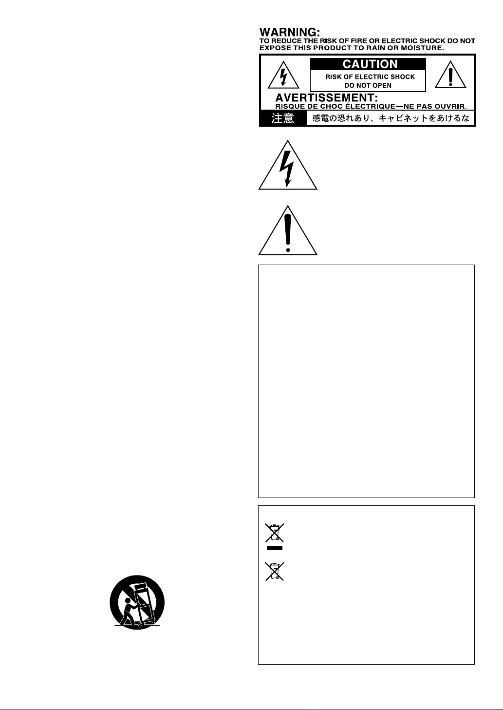
The lightning flash with arrowhead symbol
within an equilateral triangle, is intended to
alert the user to the presence of uninsulated
“dangerous voltage” within the product's
enclosure that may be of sufficient
magnitude to constitute a risk of electric
shock to persons.
The exclamation point within an equilateral
triangle is intended to alert the user to the
presence of important operating and
maintenance (servicing) instructions in the
literature accompanying the product.
THE FCC REGULATION WARNING (for USA)
This equipment has been tested and found to comply with
the limits for a Class B digital device, pursuant to Part 15 of
the FCC Rules. These limits are designed to provide
reasonable protection against harmful interference in a
residential installation. This equipment generates, uses, and
can radiate radio frequency energy and, if not installed and
used in accordance with the instructions, may cause
harmful interference to radio communications. However,
there is no guarantee that interference will not occur in a
particular installation. If this equipment does cause harmful
interference to radio or television reception, which can be
determined by turning the equipment off and on, the user is
encouraged to try to correct the interference by one or more
of the following measures:
•Reorient or relocate the receiving antenna.
•Increase the separation between the equipment and
receiver.
•Connect the equipment into an outlet on a circuit different
from that to which the receiver is connected.
•
Consult the dealer or an experienced radio/TV technician for help.
Unauthorized changes or modification to this system can
void the user’s authority to operate this equipment.
Notice regarding disposal (EU only)
When this “crossed-out wheeled bin” symbol is
displayed on the product, owner’s manual, battery, or
battery package, it signifies that when you wish to
dispose of this product, manual, package or battery
you must do so in an approved manner. Do not
discard this product, manual, package or battery
along with ordinary household waste. Disposing in
the correct manner will prevent harm to human
health and potential damage to the environment. Since the
correct method of disposal will depend on the applicable
laws and regulations in your locality, please contact your
local administrative body for details. If the battery contains
heavy metals in excess of the regulated amount, a chemical
symbol is displayed below the “crossed-out wheeled bin”
symbol on the battery or battery package.
*All product names and company names are the trademarks or
registered trademarks of their respective owners.

3
Table of Contents
Introduction.............................................................................................. 4
Welcome!................................................................................................................................. 4
Main features ........................................................................................................................... 4
Quick start ............................................................................................... 5
Setup ....................................................................................................................................... 5
Checking out the preset programs .......................................................................................... 5
Switching between the user programs .................................................................................... 6
Top and rear panels.................................................................................. 7
Top panel ................................................................................................................................. 7
Rear panel ............................................................................................................................. 11
About the three operating modes ............................................................ 13
Preset mode (recalling preset programs).............................................................................. 13
Manual mode......................................................................................................................... 13
Channel Select mode (recalling user programs) .................................................................. 14
Creating and saving sounds .................................................................... 14
Creating a sound ................................................................................................................... 14
Adjusting the noise reduction ................................................................................................ 15
Saving a program .................................................................................................................. 16
Checking the original values saved in a program ................................................................. 16
Restoring the factory settings ............................................................................................... 17
Using the tuner ....................................................................................... 18
Using a foot switch (VOX VFS5) .............................................................. 19
Foot switch operations in Channel Select mode ................................................................... 19
Foot switch operations in Preset or Manual modes .............................................................. 19
Using a foot controller (VOX VC-12SV) .................................................... 20
Expression pedal setting ....................................................................................................... 20
Assigning a function to the expression pedal (Quick Assign) ............................................... 21
If you don’t want any function to be assigned to the expression pedal ................................ 22
Minimum and maximum values for the expression pedal ..................................................... 22
Signal path ............................................................................................ 24
What is Valvetronix Pro? ........................................................................ 24
About the amp models and effect types ................................................... 25
Amp models .......................................................................................................................... 25
Pedal effects .......................................................................................................................... 30
Modulation and delay effects ................................................................................................ 32
Reverb effects ....................................................................................................................... 35
Troubleshooting ...................................................................................... 36
Specifications ......................................................................................... 38
Song preset program.............................................................................. 39
Program sheet........................................................................................ 40

4
Introduction
Welcome!
Thank you for purchasing the VOX Valvetronix Pro VTX150 Neodymium
modeling guitar amplifier.
To help you get the most out of your new amplifier, please read this manual
carefully.
Get ready to enjoy amazing guitar tones from your new VTX150 Neodymium.
Main features
•This amp uses the VOX Valve Reactor power amp circuit featuring the EL84
(6BQ5) vacuum tube that amps such as the VOX AC30 use as their power tube,
generating real tube amp sounds that reproduces the feel and tone of the
original amplifier.
•Sophisticated modeling technology is used to provide forty-four different amp
models.
•Twenty-five high-quality effects are built-in. You can use up to four effects
including noise reduction simultaneously (or up to five effects if you use
“multiple effects”).
•You can create a sound using the desired amp and effect, and save it in the
memory as one of eight programs (two banks x four channels). Programs can
be switched while you perform, either from the top panel or from a foot switch
connected to the rear panel (Channel Select mode). For each amp model, three
preset programs—Basic, Effect and Song—are provided, giving you a total of
132 programs (Preset mode). The song programs reproduce the tones of classic
hits played by famous guitarists.
•Manual mode lets you use the VTX150 Neodymium as a conventional guitar
amp. The physical positions of the actual knobs will be applied to the sound.
•By connecting an optional (separately sold) VC-12SV foot controller or VFS5
foot switch, you can use your foot to switch programs, turn effects on/off, or
use tap tempo to set the delay time or modulation speed. If a VC-12SV foot
controller is connected, you’ll be able to save and access a total of 16 programs,
as well as control a wah pedal or volume pedal, further expanding your live
performance possibilities.
•The power level control lets you adjust the output wattage of the power amp.
•An extension speaker output jack is provided. By connecting your favorite
guitar speaker cabinet (150W 8 ohms), you can obtain up to 300W of output
power.

5
•You can use the effects loop jacks to insert an external effects processor in a
loop connection.
•The built-in auto tuner lets you tune a guitar that’s connected to the INPUT
jack.
•The AUX IN jack lets you connect a CD/MP3 player, enabling you to play
guitar along with recorded music.
Quick start
This Quick Start section is for those of you who would like to start using your
new amp right away.
This manual contains information that will help you take full advantage of
your Valvetronix amp, so be sure to read the rest of it after reviewing the Quick
Start section.
HINT: Illustrations of the top panel and rear panel are provided in “Top
and rear panels” (p. 7), so you can refer to them as you try out your amp.
Setup
1. Turn the MASTER volume (p. 8) control on the amp all the way down.
2. Connect the included power cable to the AC power connector on the rear
panel, and plug the other end into an AC outlet.
3. Plug the cable that’s connected to your guitar into the INPUT jack on the top
panel.
4. Turn on the POWER switch.
5. Slowly raise the MASTER volume to adjust the volume.
HINT: The POWER LEVEL control adjusts the output level of the power
amp.
NOTE: There may be no sound for several seconds until the vacuum tube
warms up. This is not a malfunction.
Checking out the preset programs
1. Press the top Panel PRESET switch.
The PRESET LED will light up (Preset mode).

6
2. Turn the AMP selector to choose an amp model.
A preset program for a sound that is typical of each amp model will be re-
called, and the GAIN, VOLUME, TREBLE, MIDDLE, BASS, and effect settings
will switch automatically.
HINT: The amp models are organized into four banks, each bank containing
eleven models (a total of forty-four). Press the AMP switch to change banks.
Each time you press this, the AMP LED will switch to green, orange, red, or
blue and you’ll switch to amp banks STD, SPL, CST and EXT. Each of the forty-
four amp models has three preset programs (a total of one hundred and thirty-
two programs). In Preset mode, pressing the PRESET switch will cycle the
PRESET LED among green, orange, and red, switching among preset programs
1 (basic), 2 (effect), and 3 (song).
Each song program reproduces the tone of a hit played by a famous guitarist.
See the chart on page 39 for a list of the songs presets included with your
amplifier.
Switching between the user programs
1. Press one of the top panel CHANNEL switch (CH1, CH2, CH3, or CH4).
The LED for the CHANNEL switch you pressed will light up, and the user
program specified for that channel will be recalled (Channel Select mode).
HINT: The user programs are organized into two banks, each bank con-
taining four channels (a total of eight programs). Press the CHANNEL
BANK switch to switch banks. Each time you press it, the BANK LED will
change between green and red, switching between channel banks 1 and 2.
If an optional (separately sold) VC-12SV foot controller is connected,
you’ll be able to use four banks (a total of 16 programs). To switch to
banks 3 or 4, use the VC-12SV’s BANK UP/DOWN switches and foot
switches [1]–[4].
HINT: You can store your own favorite sounds in a program. For details,
please refer to “Saving a program” (p. 16).

7
PRESET LED
PRESET switch
MANUAL LED
Top and rear panels
In this chapter we're going to take a look at the top and rear panels of your
Valvetronix amp.
Top panel
1
2
4
3
5 6 7
8 9
1. INPUT section
INPUT jack
This is where you plug in your guitar.
2. PRESETS/MANUAL section
PRESET switch and LED, MANUAL LED
Use this to switch to Preset mode or Manual mode,
and to select preset programs (basic, effect, song).
Pressing the PRESET switch repeatedly will cycle
the program among basic, effect, and song. Press the
PRESET switch for more than one second to engage
Manual mode.
In Preset mode you can use the AMP switch/selector to select typical sounds
(preset programs) for each amp model. The PRESET LED will be lit green
(basic), orange (effect), or red (song) when you’re in Preset mode.
In Manual mode, the sound will reflect the physical position of all knobs
except the VALUE and DEPTH knobs. This lets you use the VTX150 Neody-
mium just as if it was a conventional guitar amp. The MANUAL LED will be lit
when you’re in Manual mode.

8
AMP LED
AMP selector
AMP switch
3. AMP section
Here you can adjust the settings for the amp using
the traditional VOX “chicken head” knobs.
AMP switch and selector, LED
Here you can select the amp mode.
Each time you press the AMP switch, the bank and
AMP LED color will change as follows:
• STD (Standard): green
• SPL (Special): orange
• CST (Custom): red
• EXT (Extra): blue
Use the AMP selector to choose a model within the selected amp bank.
The operation of the gain circuit, and the response of the tone controls and
their location within the circuit are all switched according to the amp model
that you select here.
In Preset mode (i.e., when the PRESET LED is lit-up), you can recall preset
programs that contain sounds and effect settings that are typical of each amp
model.
GAIN control
This adjusts the pre-amp gain of the selected amp model.
VOLUME control
This adjusts the volume of the selected amp model.
TREBLE, MIDDLE, BASS controls
These adjust the tone for the high, mid, and low-frequency ranges. The
changes that are produced by each control will differ depending on the amp
model that you’ve selected.
MASTER volume
This adjusts the volume that is output from the pre-amp to the Valve Reactor
power amp. This setting will change the amount of the Valve Reactor’s distor-
tion.
NOTE: The MASTER volume setting is not programmed.
NOTE: The amount of Valve Reactor distortion is also affected by the
GAIN control and VOLUME control. With some settings, there will be
almost no distortion.

9
PEDAL selector VALUE knob
TUNER (BYPASS) LEDs
BANK switch
BANK LED
TUNER (BYPASS) switch
CHANNEL LED
CHANNEL switch
4. CHANNEL/TUNER section
BANK and CHANNEL switches, LEDs
Use the BANK switch to
select the channel bank.
In Channel Select mode,
the BANK LED will be
lit-up green or red.
Use the CHANNEL
switches to select chan-
nels. The LED of the selected channel will be lit up. To save a new program,
hold down the desired CHANNEL switch for two seconds or longer.
If you want to save a new program in a different bank, hold down the BANK
switch for 0.5 seconds or longer (until the BANK LED starts blinking) and
select the desired destination bank (p. 16 “Saving a program”).
HINT: If you’re using the optional (separately sold) VC-12SV foot control-
ler and bank 3 or 4 is selected, the BANK LED will be unlit. Use the VC-
12SV’s BANK UP/DOWN switches to select bank 3 or 4.
When the tuner function is turned on, the BANK and CH 1–4 LEDs will indicate
the string number (a pitch note closest to the input sound) (p. 18 “Using the
tuner”).
TUNER (BYPASS) switch and LED
Pressing the TUNER (BYPASS) switch will turn all effects off (bypass), and
engage the tuner function. If you want to tune your instrument with the amp
output muted, press the TUNER (BYPASS) switch for one second or longer.
When the tuner function is turned on, the TUNER (BYPASS) LEDs will display
the tuning status (p. 18 “Using the tuner”).
5. PEDAL section
Here you can adjust the settings for pedal
effects.
For details on each effect, please refer to “Pedal
effects” (p. 30).
PEDAL selector
This selects the effect type. When you switch
the effect type, the parameter settings of the effect will be initialized.
VALUE knob
This adjusts the parameters of each effect.
To turn the pedal effect off, rotate this knob all the way to the left.

10
REVERB knob
6. MODULATION/DELAY section
Here you can adjust the settings for
modulation effects, delay effects, and
other effects, such as pitch shift.
For details on each effect, please refer to
“Modulation and delay effects” (p. 32).
MOD/DELAY selector
This selects the modulation type, delay type, or other effect type. When you
switch the effect type, the parameter settings of the effect will be initialized.
DEPTH knob
This adjusts the parameter of each effect, such as the depth of the effect.
You can also adjust the modulation speed and other parameters by holding
down the TAP switch and rotating the DEPTH knob.
To turn the modulation/delay effect off, rotate this knob all the way to the left.
TAP switch, LED
This sets the speed of modulation-type effects, or the delay time of delay
effects. The interval between two presses of the switch will be set as the speed
or time.
The LED will blink at intervals of the specified speed or time.
HINT: To set a precise speed or time that matches the tempo of a song,
press the TAP switch several times in rhythm with the song.
If you selected PITCH SHIFT, pressing the TAP switch repeatedly will change
the pitch setting.
If you selected FILTRON, pressing the TAP switch repeatedly will toggle
between UP and DOWN for the envelope. When UP is selected, the TAP LED
will light up.
You can also adjust the speed, pitch, or other parameters by holding down the
TAP switch and rotating the DEPTH knob.
For details, please refer to “Modulation and delay effects” (p. 32).
7. REVERB section
Here you can adjust the settings for reverb effects.
For details on each effect, refer to “Reverb effects” (p. 35).
REVERB knob
Depending on the position of the knob, this selects the reverb
type (ROOM, SPRING, or HALL) or adjusts the mix amount
of the reverb sound.
If you turn the control all the way to the left, the reverb effect will turn off.
MOD/DELAY selector TAP LED
TAP switch
DEPTH knob

11
POWER LEVEL control
PHONES jack
AUX IN jack
8. POWER LEVEL control
This adjusts the output wattage of the power amp.
When using only the VTX150 Neodymium itself: 0W–150W
When using an extension speaker: 0W–300W
NOTE: The power level setting is not saved in the
program.
9. AUX IN/PHONES section
AUX IN jack
Connect the analog output of an audio device to this jack. You
can connect a CD or MP3 player here, and then play along on the
guitar while listening to your favorite songs.
PHONES jack
Use this jack if you want to output directly to a mixer or record-
ing device, or when you want to use headphones. The signal that is output
from this jack is taken from directly before the power amp, and the cabinet
response of the guitar amp will be applied to it.
NOTE: If you plug a cable into this jack, sound will not be output from
the internal speaker or the extension speaker.
NOTE: Be sure to connect the headphones to this jack in stereo. If you
connect them in monaural, the sound will not be output through the
headphones.
Rear panel
1
2
5
36
4
1. POWER switch
This switch turns the power on or off.
2. AC power connector
This is where you connect the included power cord.

12
3. FX LOOP (Effect loop) jacks
These are loop jacks for connecting an external effects processor.
Connect the SEND jack to the input of your external effects processor. Connect
the RETURN jack to the OUTPUT of your external effects processor.
4. VOX BUS port
Connect the optional (separately sold) foot controller here.
For details on using the foot controller, please refer to “Using a foot controller
(VC-12SV)” (p.20).
NOTE: Never connect anything to this port other than the VC-12SV.
5. FOOT SW (foot switch) jack
You can connect an optional VOX VFS5 foot switch here.
For more information on using the VOX VFS5, please refer to “Using the foot
switch (VOX VFS5)” (p. 19).
NOTE: You must connect or disconnect the VFS5 while the power is off.
Malfunctions or damage may occur if you connect or disconnect the foot
switch while the power is on.
NOTE: Take care that you don’t mistakenly connect the VFS5 to the
EXTENSION SP jack.
6. EXTENSION SP (Extension speaker out) jack
You can connect a guitar speaker cabinet here.
If a protective cap that guards against accidental insertion is attached, remove
it first.
IMPORTANT: In order to ensure correct operation, you must strictly
observe the following points.
a) Use only an 8 ohm external speaker; no other impedance may be
used.
b) Do not connect a speaker whose rated input is less than 150 watts.
Doing so may damage your speaker.
c) You must use a speaker cable to connect the speaker. Don’t use a
shielded cable of the type used to connect a guitar to an amp.
d) You must turn off the power before connecting this cable. The amp
may malfunction if you connect or disconnect this cable while the
power is on.

13
About the three operating modes
Preset mode (recalling preset programs)
In Preset mode you can use the AMP switch/selector to recall programs for
each amp model: “basic” programs containing typical sounds for that amp
model, “effect” preset programs, and “song” preset programs that replicate
tones from hit songs. Each program will automatically switch the settings for
GAIN, VOLUME, TREBLE, MIDDLE, BASS, and effects. For details on the hit
songs that are programmed for each amp model, please refer to the table at end
of this owner’s manual.
Switching to Preset mode
If the PRESET LED is dark, you’re not in Preset mode. Press the PRESET
switch; the PRESET LED will light up, and you’ll be in Preset mode.
Recalling a preset program
Each of the forty-four amp models contains three preset programs: “basic,”
“effect,” and “song” (a total of one hundred and thirty-two programs).
With the PRESET LED lit, use the AMP switch/selector. The preset program
specified for each amp model will be selected, regardless of the position of the
top panel control knobs or EFFECTS selector. If you recall a preset program
while the effects bypass is enabled, the bypass will be cancelled.
In preset mode, pressing the PRESET switch will make the PRESET LED cycle
through green, orange, and red, switching among preset programs Basic,
Effect, and Song.
Manual mode
When the VTX150 Neodymium is in Manual mode, it will behave like a conven-
tional guitar amp. In other words, the sound will reflect the actual position of all
the top panel selectors and control knobs (except for the VALUE and DEPTH
knobs).
Switching to Manual mode
If the MANUAL LED isn’t lit, the unit is not in Manual mode. Press and hold
down the PRESET switch for one second or longer; the MANUAL LED will
light up, and the unit will enter Manual mode.
NOTE: In Manual mode, if you adjust a parameter setting that is not affected
by a knob position (such as the effect parameter and the noise reduction
settings), the adjusted setting will be saved automatically, and that same
setting will be recalled the next time the unit enters Manual mode. However, if
at that time the PEDAL or MOD/DELAY selector is set to a different position
than previously, the default parameter settings for that effect type will be
loaded.

14
Channel Select mode (recalling user programs)
In Channel Select mode you can use the BANK switch and CHANNEL
switches to recall the programs that are saved in each channel of the bank; all
of the amp and effect parameters will switch automatically.
Switching to Channel Select mode
If the BANK and CHANNEL LEDs aren’t lit, you’re not in Channel Select
mode. Press the BANK switch or a CHANNEL switch; the BANK and CHAN-
NEL LEDs will light up, and you’ll be in Channel Select mode.
Switching channels
Press a CHANNEL switch to change channels. The program specified for that
channel will be selected, regardless of the position of the top panel selectors
and control knobs. If you press the BANK switch, the bank will change, and
the channel of the same number that had been selected in the previous bank
will be selected.
HINT: If an optional (separately sold) VOX VFX5 foot switch or VC-12SV
foot controller is connected to the rear panel, you can use your foot to
switch banks or channels. For details, please refer to “Using a foot switch
(VOX VFS5)” (p.19) and “Using a foot controller (VC-12SV)” (p.20).
Creating and saving sounds
You can create a sound either by starting with an existing program that’s close
to what you have in mind and then editing it, or by creating the sound “from
scratch” (i.e., from an initialized state).
Creating a sound
Here’s how to create a sound from scratch.
1. Enter Manual mode.
2. Use the TUNER (BYPASS) switch to bypass the effect (the TUNER (BYPASS)
LEDs will be lit up).
If you want to use an effect, you’ll add it last.
3. Use the AMP switch/selector to select the amp that you want to use.
HINT:
For details on the amp models, please refer to “Amp models” (p. 25).

15
4. Adjust the top panel knobs such as GAIN, VOLUME, TREBLE, MIDDLE, and
BASS.
5. Turn the VALUE knob to set the noise reduction. This setting is also saved in
the program. For details, please refer to “Adjusting the noise reduction” (p. 15).
HINT: Adjust the noise reduction so that there’s no unwanted noise when
you’re not playing your guitar.
6. Press the TUNER (BYPASS) switch once again to defeat bypass (the TUNER
(BYPASS) LEDs will be dark).
7. Set the effect.
If you plan not to use effects, set the VALUE, DEPTH, and REVERB knobs to
the “OFF” position. If the knobs have already been set to “OFF,” set them to
any position other than “OFF,” then set them back to “OFF.”
If you plan to use effects, select an effect, and adjust it as desired.
For example if you want to add delay, turn the MOD/DELAY selector to
“A.DELAY.” If the selector is already at “A.DELAY,” turn it to some other effect
type and then back to “A.DELAY.”
Use the TAP switch and DEPTH knob to set the delay time or delay level (the
amount of delay sound that is added).
DELAY LEVEL: Turn the DEPTH knob (without holding down a
switch).
DELAY TIME: Press the TAP switch twice (at the desired timing
interval).
DELAY FEEDBACK: Turn the DEPTH knob while holding down the TAP
switch.
HINT: For details on the effect types, please refer to “About the amp
models and effect types” (p. 25).
Adjusting the noise reduction
Here’s how to adjust the way that noise is suppressed.
NOTE: Noise reduction is specified individually for each program. In
Preset mode or Channel Select mode, the noise reduction setting will be
lost if you switch to a different program or to Manual mode or turn off the
power before saving.
1. Press the TUNER (BYPASS) switch to make the TUNER (BYPASS) LEDs light
(Effect Bypass On).
2.
Turn the VALUE knob to adjust the sensitivity of the noise reduction. Turning
the knob toward the right will produce stronger noise reduction. If the knob is
turned all the way to the left, noise reduction will be off and will have no effect.

16
NOTE: Depending on the guitar you’re using, raising the noise reduction
too high may cause notes to be cut off.
3.
Press the TUNER (BYPASS) switch to make the TUNER (BYPASS) LEDs go dark.
Saving a program
When you’ve created a sound that you like, here’s how to save (write) it.
HINT: If you’re saving to a channel in the same bank, proceed from step 3.
1. Hold down the BANK switch for 0.5 seconds or longer. The BANK LED will
blink.
2. Press the BANK switch to select the save-destination bank.
HINT: If an optional (separately sold) VC-12SV foot controller is con-
nected, you can use the controller’s BANK UP/DOWN switches to select
the save-destination (banks 1–4).
HINT:
If you decide to cancel the Write operation, press the TUNER (BYPASS)
switch
at this point. The LED will stop blinking, and you’ll return to the
previous mode.
3. For two seconds or longer, hold down the CHANNEL switch of the channel in
which you want to save the sound. The LED will change from blinking lit. The
program will be saved in that channel, and that bank and channel will be
selected.
NOTE: The program that was previously in that location will be overwrit-
ten; i.e., the program that had been in the channel you selected in step 3
will be lost.
NOTE: The setting of the TUNER (BYPASS) switch is not saved in the
program.
NOTE: If you’re creating your sound in Preset mode or Channel Select
mode, the changes that you made will be lost if you switch to another
program, to Manual mode or turn off the power before saving.
Checking the original values saved in a program
The original value indication lets you check the parameter settings that are
saved in a program.
When you turn a knob to change the value of a parameter, the PRESET LED (if
you’re in Preset mode) or the LED of the selected channel (if you’re in Channel
Select mode) will momentarily go dark when the edited value matches the
value that’s stored in the program.

17
HINT: When you’ve found a program that you like, and are interested in
knowing the actual settings, you can use this original value indication to
find out.
NOTE: The MASTER volume and POWER LEVEL controls are not pro-
grammable, so the original value indication is not available for these
controls. The original value indication will not appear when the tuner
function is turned on in Channel Select mode, nor when the unit is in
Manual mode.
Restoring the factory settings
Here’s how to restore all settings of the VTX150 Neodymium to their factory-
set state.
NOTE: This operation will erase all programs that had been saved to
channels, and will initialize the factory-set programs.
NOTE: This will also initialize the effect and noise reduction settings that
you made in Manual mode.
1. Turn off the power.
2. While holding down the CH1 and CH4 switches, turn on the power. When the
BANK and CHANNEL LEDs start blinking, release the two switches you had
been holding down.
HINT: If you decide to cancel initialization at this point, press the TUNER
(BYPASS) switch.
3. Press the TAP switch. The BANK and CHANNEL LEDs will change from
blinking to lit, and initialization will begin. In one or two seconds, initialization
will be completed, and the unit will enter Preset mode.
NOTE: Never turn off the power while initialization is in progress.

18
Using the tuner
The tuner function lets you tune a guitar that’s connected to
the INPUT jack.
HINT: If an optional (separately sold) VC-12SV foot
controller is connected, you can use your foot to use the
tuner function. For details, please refer to the VC-12SV
owner's manual.
1. Press the TUNER (BYPASS) switch. All effects will be by-
passed and the tuner function will be turned on.
Bypass indicator (No valid signal is input.)
HINT: If you want to tune your guitar with the amp output muted, hold
down the TUNER (BYPASS) switch for one second or longer. When the
amp is muted, the TUNER (BYPASS) LEDs will blink.
2. Play any open string.
NOTE: Be careful not to play other strings accidentally.
3. Tune the string casually so that, from among five LEDs (BANK LED and CH 1–
4 LEDs) only the LED that corresponds to the string lights up.
6th (E) 5th (A) 4th (D) 3rd (G) 2nd (B)
1st (E)
4. Tune the guitar precisely while observing the TUNER (BYPASS) LED indica-
tors.
Sharp
Slightly sharp
In tune
Slightly flat
Flat
5. Press the TUNER (BYPASS) switch again to complete tuning.

19
Using a foot switch (VOX VFS5)
If you connect an optional
VOX VFS5 foot switch (sold
separately) to the rear panel
FOOT SW jack, you’ll be able
to switch banks/channels and
turn effect bypass on/off using your foot.
NOTE: You must connect or disconnect the foot switch while the power is
off. Malfunctions or damage may occur if you connect or disconnect the
foot switch while the power is on.
NOTE: Do not press two or more foot switches simultaneously. Doing so
may cause malfunctions.
Foot switch operations in Channel Select mode
Switching banks/channels (BANK, CH1–4 switches)
In Channel Select mode, you can press the VFS5’s switches to change the bank
or channel.
NOTE: You can’t change to Channel Select mode by pressing the VFS5’s
switches in Preset or Manual modes. Nor can you save a program by
holding down the VFS5’s CH1–4 switches.
NOTE: Use of the top panel will not be reflected by the VFS5’s LEDs.
Tap to set the speed/time (CH1–4 switches)
You can set the speed of a modulation effect or the time of a delay effect by
pressing the CHANNEL switch of the same number as the selected channel.
The time will be set to the interval between two presses of this switch.
Foot switch operations in Preset or Manual modes
Tap to set the speed/time (CH3 switch)
In Preset or Manual modes, you can set the speed of a modulation effect, or the
time of a delay effect by pressing the VFS5’s CH3 switch. The time will be set
to the interval between two presses of this switch.
Effect on/off (CH1, 2, 4 switches)
In Preset or Manual mode, you can press the VFS5’s CH1, 2 or CH4 switches to
turn PEDAL, MOD/DELAY, and REVERB effects on/off respectively.

20
NOTE: The effect on/off setting is independent for each program. In
Preset mode or Channel Select mode, any changes you make will be lost if
you don’t save the edited program before switching to another program
or to Manual mode, or before turning off the power.
Using a foot controller (VOX VC-12SV)
If an optional (separately sold) VOX VC-12SV foot controller is connected, the
number of user programs is increased to 16 (4 banks x 4 channels), and you’ll
be able to select banks 3 and 4 which cannot be selected from the amp itself.
HINT: For details on
how to save a
program to bank 3
or 4, please refer to
“Saving a program”
(p.16).
The VC-12SV also allows
you to control the following with your foot.
-Switch banks or channels (only in Channel Select mode)
-Use the volume pedal to control the volume
-Use the expression pedal to control parameters
-Use the foot switches to turn individual effects on/off
-Use a foot switch to activate the tuner
-Use a foot switch to set the delay time and modulation speed (the Tap
function)
NOTE: Please do not connect VTX150 Neodymium to the VOX BUS SUB
connector. Two VTX150 Neodymium units can not be controlled by the
VC-12SV.
HINT: For details on connecting and operating the VC-12SV, please refer
to the VC-12SV owner’s manual.
HINT: The VC-12SV operation when the VTX150 Neodymium is in Preset
mode is the same as when it is in Manual mode. For details on operation
in Manual mode, please refer to the VC-12SV owner’s manual.
Expression pedal setting
Each of the VTX150 Neodymium's programs assigns a function to the expres-
sion pedal, allowing you to use the expression pedal to control not only wah
but a variety of other effect parameters.
HINT: If you select AUTO WAH, the expression pedal will automatically
function as a wah pedal.
Table of contents
Other Vox Amplifier manuals

Vox
Vox BC108 User manual

Vox
Vox MV50 High Gain User manual

Vox
Vox Valvetronix VT120+ User manual

Vox
Vox Berkeley II V1081 User manual

Vox
Vox VALVETRONIX AD15VT User manual

Vox
Vox av30 User manual

Vox
Vox Valvetronix AD212 User manual

Vox
Vox NIGHT TRAIN EFGSJ1 User manual

Vox
Vox Valvetronix AD120VTH User manual

Vox
Vox Night Train 50H G2 User manual

Vox
Vox AGA30 User manual

Vox
Vox DA10 User manual

Vox
Vox Valvetronix VT30 User manual

Vox
Vox Night Train 50 User manual

Vox
Vox AGA150 User manual

Vox
Vox Classic Plus AC100 User manual

Vox
Vox AC4TV User manual

Vox
Vox VALVETRONIX AD10VT User manual

Vox
Vox BRIAN MAY SPECIAL VBM1 User manual

Vox
Vox PATHFINDER BASS 10 User manual