Vox V301H User manual

1
Vox Continental models
V301H, 301J, 303J
TROUBLE-SHOOTING
COMBO-ORGANS

2
TOPICS
1. Examine for cold-solder joints
2. Repair a lied track
3. Diagnose faulty transistors in a divider circuit (including use of a signal tracer).
4. Test a tuning coil
SAFETY
• Always power-down by disconnecng at the wall socket.
DO NOT power-down using the instrument on-o switch as that leaves AC supply
voltage sll present in the machine.
• Always power-down before performing physical work on any components.
• Know where AC supply voltage is present in the instrument. Likely suspect points are
at the terminaon of the AC supply cable, at on-o switches and power-on indicator
lamps.
• Before working on an instrument, put an insulang barrier around any exposed AC
supply connecons. The barrier could be temporary, or consider a permanent x
such as ng heat-shrink tubing.
• Look for any situaons where AC supply and signal wires are mixed together. Aim to
achieve reliable physical separaon. This may also help with any hum or clicks and
pops issues.
Exposed wiring at on-o switches is a common hazard

3
1. EXAMINE FOR BAD SOLDER JOINTS
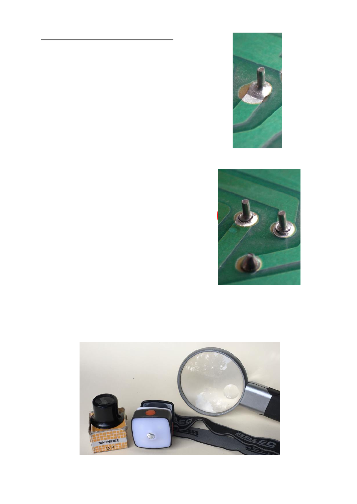
Good solder joints have a bright surface nish
and concave contour, with the lead wire
protruding from the joint. The concave shape is
the result of surface tension and is a posive
indicaon that the solder has bonded to the
component lead.
Be suspicious of any joints which appear as a
‘blob’ of solder with no lead protruding.
Cracked joints are not always this easy to spot.
Be suspicious of any joints which are
mechanically stressed or subject to vibraon.
Examples are connectors, wire terminaons or
heavier components. These will be the rst joints
to give problems.
Less extreme cracking in a joint may only be
visible under magnicaon with good lighng.
To repair a joint, rst remove the exisng solder.
Examine and, if necessary, mechanically clean
the surfaces before resoldering.
Photo credit, Wikimedia
Commons
Some helpful items when fault-nding; jeweller’s loupe, head torch and
illuminated magnifying glass
Photo credit, Wikimedia
Commons

4
Use a temperature controlled soldering iron, set to around 450C.
While it may seem counter-intuive, the possibility of track or component damage is
reduced by having a hot iron, so geng the joint made quickly.
This is an 80 Wa unit which provides ample heang capacity for circuit card repairs.
The combinaon of good solder-sucker and uxed copper-braid will
greatly assist the removal of solder, especially where the card has copper
tracks on one side only.
A hobby-blade is useful to (gently) scrape surfaces clean, backed up by a
ux-pen to aid resoldering. The dried ux can be le in-place.

5
2. HOW TO PREVENT A LIFTED TRACK
To avoid a lied track, use your soldering iron and de-soldering aids with care and avoid
any mechanical force which could push the copper track away from the card substrate.
Accidents can sll happen. This was the result of
simply inserng the leads of a new component.
To make a repair, if using a heavier gauge nned copper wire, form hooks to go around the
component lead ends. For longer wires, solder the wire to the original track at one or more points.
Alternavely, if the component lead is long
enough, it can be bent over to form a bridge to
a good secon of track.
A card of fuse-wire can be a handy source of
two smaller wire sizes. Wrapping the wire
around the component leads achieves a good
mechanical connecon prior to soldering.

6
Both hand and machine soldered cards oen were not cleaned in manufacture. The ux residue is
safe to leave, but doesn’t look great. Isopropyl alcohol is the best solvent. As a scrubbing tool a
toothbrush works well, but should not be used where digital integrated circuits are involved.
Special an-stac brushes are available in that situaon.
Hold the card vercal to sluice the dirty uids away, but ensuring that the uids don’t get onto, or in,
any connectors.
A light spray of circuit board lacquer will leave your card looking beer than new.

7
3. DIAGNOSE FAULTY TRANSISTORS IN A DIVIDER CIRCUIT
Many organ types use a series of divide-down circuits to derive the descending octaves of
a given note.
A typical divide-down stage comprises a pair of transistors plus peripheral resistors and
capacitors. Depending on how it’s been drawn, it’s usually possible to recognise the
crossed-connecon transistor pairs in an keyboard circuit diagram.
A divide-down stage is also known as a bistable ip-op, or latch. It has two stable output
states (o and on) and is triggered to change states by an input signal.
In a keyboard, the output of one stage is also the input to the next, each stage in turn
producing the next lowest octave.
Example of a divide-down stage from a VOX Connental 301
Output Input

8
VOX divider cards
Card A is from a UK manufactured Connental, circa 1965. It uses PNP transistors
Card B is also from a UK manufactured double-manual Connental (with percussion).
It uses NPN transistors.
Both are built on the same printed circuit biscuit and have male pin connectors. However,
they are not interchangeable as they have opposite power supply voltage polaries.
Card C is from a US manufactured Connental, model V301H, circa 1966.
It uses PNP transistors and has female socket connectors.
The following pages will explore PNP and NPN transistors.
VOX DIVIDER CARDS

9
PNP TRANSISTORS
Tesng a BC556 PNP transistor

10
NPN TRANSISTORS
Tesng a BC337 NPN transistor

11
With some experimentaon, it’s possible to determine whether an unknown device is PNP
or NPN, and which leg is the base.
The test will not dierenate between emier and collector, but with reference to the
circuit diagram it’s usually possible to idenfy these by observing what components are
connected to that leg. (Oen, the emier will be connected to circuit ground, but it’s not
guaranteed.)
Diodes and transistors are the two components which can be successfully tested in-circuit.
Aempts to test resistors and capacitors in-circuit will, at best, only give indicave
readings. For an accurate result, rst de-solder one leg of the component and li it away
from the circuit card track.
A Google search of the part number will usually nd the data and pin-out info for any
transistor.
Three methods of fault nding a divider card will be discussed in the following pages:
a) In the instrument, using the keyboard
b) In the instrument using an audio probe
c) On the bench using an audio probe or oscilloscope

12
3a. DIAGNOSE A FAULTY CARD(S) USING THE KEYBOARD
• With only the 16’ drawbar out, play a descending chromac scale. Listen for any notes
which are missing, quiet, or the wrong octave
• Tag any faulty keys with masking tape, note the fault on the tape
• Repeat these two steps with only the 8’ drawbar out, then only the 4’ out
• At the end of this process, you will have a good picture of where any faults are located
If a note is missing in all octaves
and footages, it’s likely you have a
faulty oscillator.
This topic will be covered later in
the document.
If a note is missing in just one octave and one
footage, it’s likely to be the result of a broken
contact spring.
Replacement of a broken spring is not covered
here.
In all other cases, if you have a note (or
notes) not playing, or playing higher
than it should be, it’s likely to be due to
at least one faulty divider stage.
In this case, remove the card for bench
tesng.

13
An audio signal tracer is a simple, but useful, test tool which will be referred to in following
pages. A quick Google search will nd several design approaches to making your own.
In the example below a 0.1mfd 400 volt capacitor is used to block any DC voltage and a
potenometer included to allow the sensivity to be readily controlled.
The components are housed in a small box complete with a guitar socket. In this way it can
be used plugged into a small pracce amp.
WARNING
A signal tracer must only be used to check low-level audio signals.
For your safety, DO NOT use an audio probe in circuit areas where mains AC voltage,
or any high voltages, may be present.
SIGNAL TRACER
Ground connector
Probe point

14
3b. DIAGNOSE A FAULTY CARD(S) USING A SIGNAL TRACER
With the cards in the instrument:
• Touch the probe on each of the six audio outputs of each card, moving from the
highest to lowest octave
• Listen for an even progression of tones
• Tag any faulty cards nong the faulty octave (s)
UK and USA cards have the same pinout arrangement for the six octaves the cards
generate.

15
3c. BENCH TESTING
• The following checks can be done with an audio probe or oscilloscope.
• The cards can be safely powered from a 9 volt baery
• A simple test jig can be helpful. A small press-buon switch in the baery circuit is
useful when checking for reliable oscillator start-up and avoids constant connecng and
disconnecng of the baery.
While not having the exact same pitch
spacing as the card, a six or eight-way
‘Molex’ connector allows easy connecon
to the male pins.
** The baery polarity shown here is for a
PNP card.
Reverse the polarity for an NPN card
Here, a length of medium gauge nned
copper wire with the end folded over
double makes an adequate male connector
pin for tesng purposes

16
3c. BENCH TESTING cont.
Once it’s been established that you have at least one faulty divider stage, you will need to
locate the relevant components. For both UK and USA cards, the sequence of divider
stages one to six begins nearest the oscillator circuit.
Idenfy each pair of transistors which comprise a divider stage. In the UK cards above, the
output of each stage is on the collector of the right-hand-side transistor of each pair
(where it connects to the 2K2 resistor) as shown by the red arrows.
In the USA card above, several of the resistors and capacitors for each stage are located on
the vercal ‘couplates’. The yellow wires connect the output of one stage to the input of
the next. The stage output can also be found on the centre leg (collector) of the le-hand-
side transistor of each pair, as shown by the red arrows. Always start your tesng from the
highest frequency end, which in all cases is nearest to the oscillator.

17
These oscilloscope traces illustrate a correctly working divider stage. Each rising edge (red
line) of the input signal triggers a change of state in the output signal, so halving the
frequency, which equates to lowering the note by one octave.
Two fault condions were seen in the
instrument I repaired. Either the divider stage
was not switching at all (atlining) or the
switching was not reliable (failure to latch) as
shown in the trace. Either fault will aect all
following stages.
OUTPUT
Each divider has a simple resistor-capacitor network which shapes the square-wave
divider output into a, more musical, rounded sawtooth paern, sll rich in harmonics.

18
For all eight cards repaired from a USA
manufactured Connental, low-gain transistors
were the cause of every divider fault.
A transistor gain test funcon is included in
many digital mul-meters. Select the correct
test for the type of transistor you are working
with (PNP or NPN) and be sure to insert the
transistor leads into the correct sockets.
In technical literature, gain may be shown under the
term ‘hfe’. It is the rao of collector current divided by
the base current at some nominated test condion. The
design gain of a transistor will be presented in a range
(say 70-250).
Early type transistors as found in a Connental typically
have gains considerably lower than can be expected
from more modern devices. This example has a gain of
sixty.
This group represents a typical range of gain values (20 –92) in transistors from a USA
manufactured Connental. A gain of less than 30 will almost certainly cause faults in a
divider stage. It seems likely that, at least for this generaon of devices, the transistors
may loose gain over me.
Note also that the gain of these transistors was measured at room temperature.

19
The gain of a transistor is temperature dependant. In the images above, the same
transistor is tested for gain at room temperature, then chilled with freeze spray.
This result suggests that chilling is not a useful test when looking for a marginal transistor,
as the gain of even a ‘good’ transistor will be reduced to the point that it would cease to
work in a divider stage.
However, to ush out any marginal transistors, it may be a useful to cool a divider card in a
refrigerator before tesng.

20
REPLACEMENT OF FAULTY TRANSISTORS
There are two opons when replacing faulty transistors.
If you have access to transistors of the same part number, you may prefer to use those to
maintain authencity. Especially if your card has germanium PNP transistors, it would be
prudent to source replacements of the same part number, or a near equivalent. Gain test
the replacement parts before ng, and select the higher gain devices for use.
If your card has silicon NPN transistors, then any modern general purpose NPN transistor
should be ne as a replacement. Types BC337, BC546, BC547 have been used successfully.
Transistor pin orientaon for a UK manufactured card. The pin
orientaon is the same for both the PNP and NPN versions of the card.
B C E
Transistor pin orientaon for a USA manufactured card.
Here, BC337 transistors have been ed as replacements.
Note that the base and collector legs have been crossed to match the
transistor pin orientaon to the circuit card hole placement.
C B E
B C E
This manual suits for next models
2
Other Vox Musical Instrument manuals

Vox
Vox VUP-33-SOW User manual

Vox
Vox SDC-1 mini User manual

Vox
Vox Giulietta VGA-5TPS User manual

Vox
Vox Giulietta VGA-3PS User manual

Vox
Vox CONTINENTAL TYPE 1 HARMONICA KEY OF A User manual

Vox
Vox Bobcat S66 User manual

Vox
Vox Starstream Series User manual

Vox
Vox Continental Organ User manual

Vox
Vox Giulietta VGA-3D User manual

Vox
Vox Electric Ukulele User manual
Popular Musical Instrument manuals by other brands

SAWTOOTH
SAWTOOTH ST-WDCP-88 Operation instructions

Kawai
Kawai CN470 owner's manual

Yamaha
Yamaha CLAVINOVA CLP-635 Firmware update guide

Percussion Play
Percussion Play Freechimes Diatonic Symphony installation instructions

Yamaha
Yamaha Portable Grand YPG-225 owner's manual

Roland
Roland V-ACCORDION FR-5 owner's manual