Voxx Directechs DS3+ User manual

HONDA7
INSTALLATION GUIDE
This product is intended for installation by a professional installer only! Attempts to install this
product by a person other than a trained professional may result in severe damage to a vehicle’s
electrical system and components.
2021-11-24
© 2021 VOXX•DEI LLC.
DS3+ / DS4+
Designed by Installers for Installers

Contents
Introduction ..................................................................................................................................................................................... 3
Vehicle application guide ...................................................................................................................................................... 4
Pre-installation and application warnings ............................................................................................................................ 5
Wiring diagram............................................................................................................................................................................... 6
Module programming .................................................................................................................................................................. 12
Pairing Remotes..................................................................................................................................................................... 15
8556T Temperature Sensor.................................................................................................................................................. 15
8504D Combo Sensor......................................................................................................................................................... 15
RF Systems ............................................................................................................................................................................. 15
When used in conjunction with Directed SmartStart®....................................................................................................................................................................................... 16
D2D port configuration ........................................................................................................................................................ 16
Manual Transmission .................................................................................................................................................................... 17
LED diagnostics and troubleshooting .......................................................................................................................................... 18
Soft reset................................................................................................................................................................................20
Hard reset..............................................................................................................................................................................20
Tach learning procedure (not needed with Virtual Tach)........................................................................................................... 21
Initializing Virtual Tach (not needed with hardwired or data tach applications)............................................................. 21
Hybrid Vehicles..................................................................................................................................................................... 21
Limited Lifetime Consumer Warranty...........................................................................................................................................22
Quick Reference Guide................................................................................................................................................................23

3DS4+ HONDA7
© 2021-11-24 VOXX•DEI LLC. All rights reserved.
Introduction
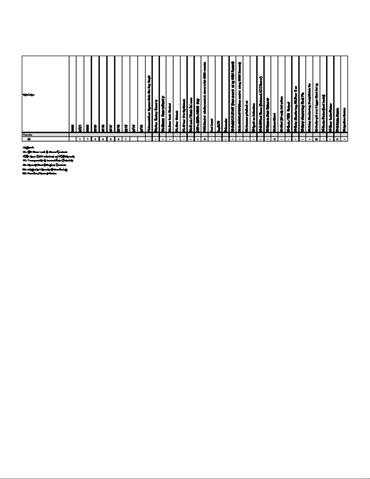
This guide provides information on the installation of the DS3/DS3+ and DS4/DS4+ modules as a digital solution. Using these modules in a
digital configuration require the module to be flashed with vehicle specific firmware. Refer to our website (www.directechs.com) and click on
the DIRECTLINK text in the header for additional information.
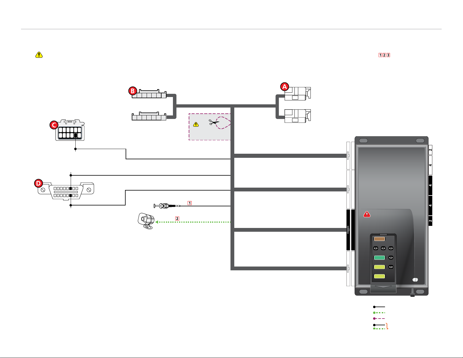
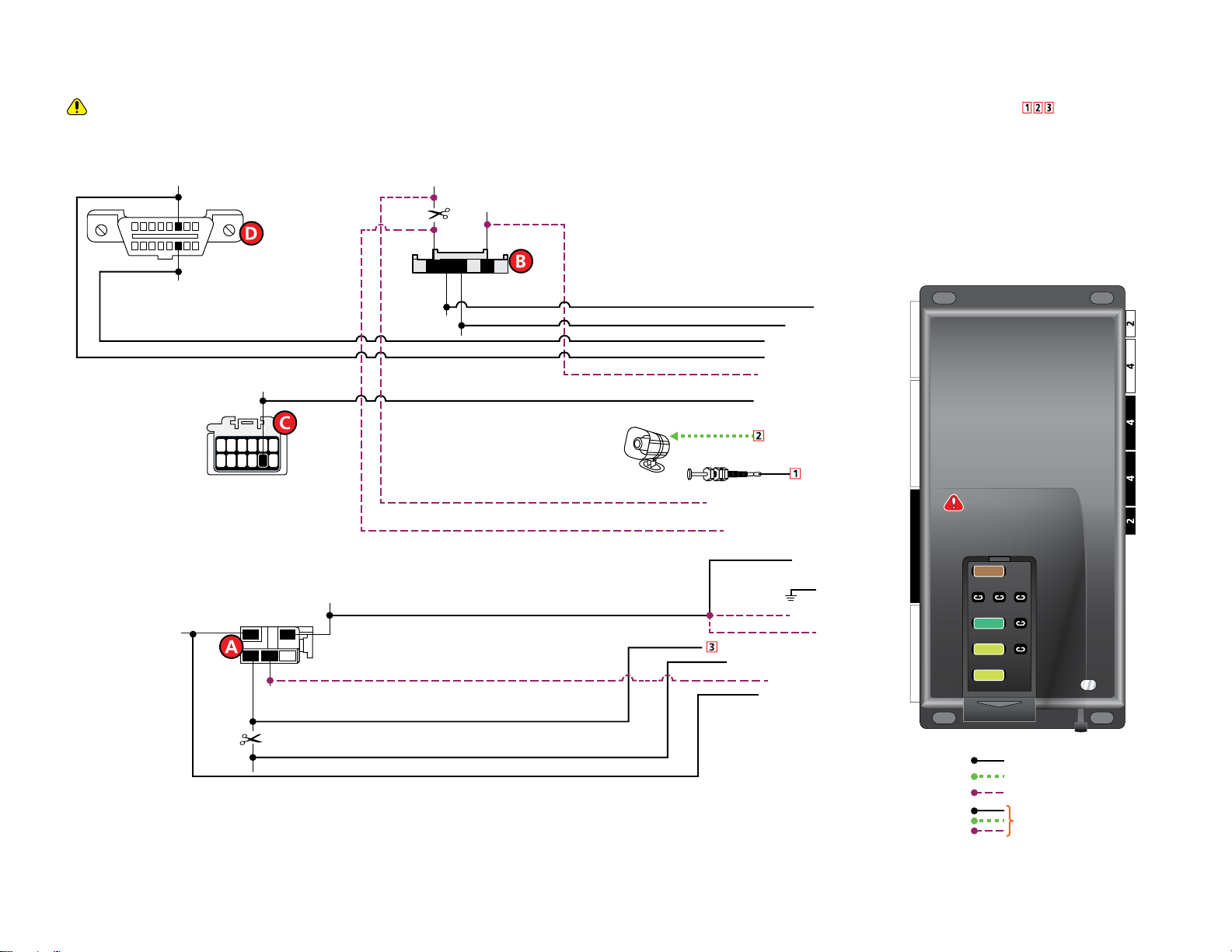
DS3/DS3+ and DS4/DS4+ modules provide an all-in-one solution for most modern vehicles, and include remote start, keyless entry, security,
and immobilizer bypass capabilities. T-harnesses may also be used in many applications for easy installation.
The following methods are available to configure modules:
• Web: www.directechs.com (DS3/DS3+ and DS4/DS4+)
• Desktop Application: Directlink DT (DS3/DS3+ and DS4/DS4+)
• Mobile Device: Directlink App (DS4/DS4+ only)
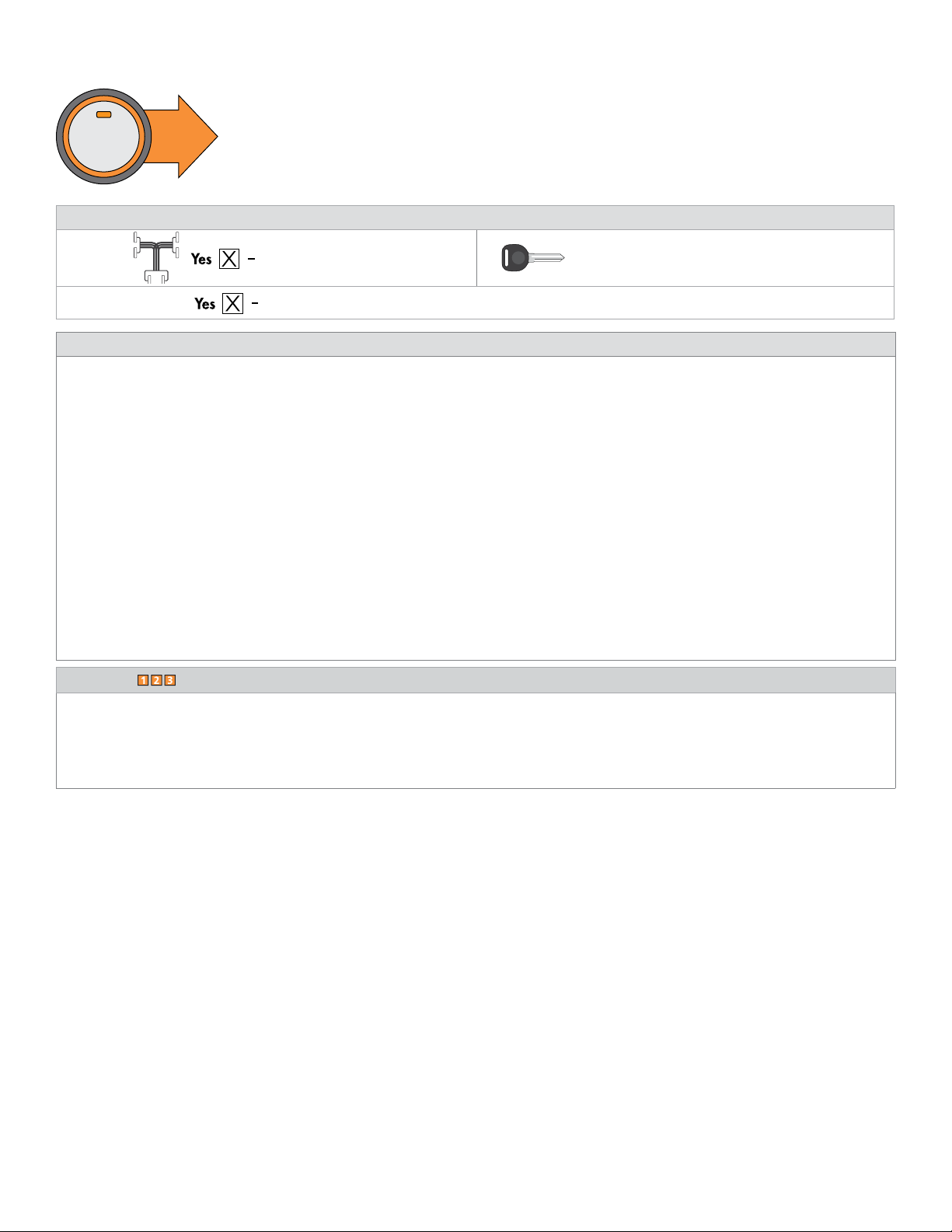
When Flashing via Directlink DT (Desktop app) or via the Web, an XKloader2 will be required.
To configure via Web or DirectLink DT (mobile app):
1. Disconnect the main module from any (+) 12V power source.
2. Connect the module to your computer using the XKLoader2.
3. Follow the steps in the pop-up window that will be displayed when the module is detected.
Notes:
•Flashing via web is only possible using Internet Explorer on Windows 8, 8.1, and 10.
•This method is not compatible with any other browser (Edge, Chrome, Firefox, etc.)
•When using Windows 11 or newer, Directlink DT is mandatory.
The DS4/DS4+ module is designed to be configured using the DirectLink application through mobile devices.
FLASH REQUIRED!
FLASH REQUIRED!
To download the DirectLink mobile application, visit the Google Play or Apple store. They can also be
configured via Web and DirectLink DT. The DS4/DS4+ features are built in Bluetooth® 4.0, allowing you to
configure and control your system. The DS3/DS3+ module is not equipped with Bluetooth®, therefore is not
compatible with the DirectLink app for mobile devices.
To configure via DirectLink DT (mobile app):
1. Follow and complete the wiring diagram(s) related to your installation through the app.
2. When installation is complete, select Configure DS4/DS4+.
3. Follow the on-screen instructions.
4 White

4DS4+ HONDA7
© 2021-11-24 VOXX•DEI LLC. All rights reserved.
Vehicle application guide
The following table lists the vehicles and features which are compatible with this product. The number assigned to each year allows you to
determine which installation type should be used for your vehicle.

5DS4+ HONDA7
© 2021-11-24 VOXX•DEI LLC. All rights reserved.
Pre-installation and application warnings
START HERE This section highlights important information for this specific firmware and will assist in pricing accordingly, as
well as bringing awareness to any operational or vehicle limitations.
Compatibilities and Requirements
T-Harness
compatible THHON3 Keys
required for
programming 1Keys required
for operation 0
Vehicle Takeover Refer to the Quick Reference Guide section for more details.
Firmware notes
Important! A DS4+ module is required for this installation, as the Relay harness (H2), 10-pin white connector is used.
The optional Plug & Play THHON3 T-Harness is sold separately.
Important! All T-Harness wires NOT listed in the diagram are NOT required for the installation. Loose wires such as Siren Output and
Hood Input may need to be pulled from the tapped section of the T-Harness. Refer to the “Wiring diagram with T-Harness” for more
information on connections and installation instructions.
Important! DO NOT turn vehicle Ignition ON with ANY vehicle connectors disconnected, including during module programming.
Failure to do so may result with errors in the instrument cluster or hidden error messages.
It is possible to get a "Keyless Starting Error" message when remote started. This message will disappear when the vehicle is started
with the key.
Power liftgate and sliding door controls are ONLY available when the engine is OFF (where applicable).
Key2GO may be required if the interface does not program using the traditional method. Refer to "Module programming" for more
information.
Unless specified otherwise, all connectors are displayed from the wire side, with the exception of the OBDII diagnostic connector.
It is important to check that the fuses are positioned correctly in the module. Proper fuse positioning is displayed on each wiring
diagram.
Refer to the "Vehicle connections" section following the installation diagram.
Footnotes
[1] The installation of an aftermarket hood pin is ONLY required on vehicles that are NOT equipped with a factory hood pin or if NOT
supported in data.
[2] The siren is ONLY required when enabling the security features during module flashing.
[3] The Green wire is OPTIONAL for starter disable and anti-grind applications.

6DS4+ HONDA7
© 2021-11-24 VOXX•DEI LLC. All rights reserved.
Wiring diagram
Type 1a - Wiring diagram with T-Harness (THHON3)
Refer to "Pre-installation and application warnings" for important information, such as the description of each special note referenced in the diagram ( ).
123456
789101112
16
8
9
1
Wiring diagram with T-Harness (THHON3)
HS CAN High 1: Orange/Green
HS CAN Low 1: Orange/Brown
(-) Parking Lights Output: Lt. Blue/Black
OBDII
Diagnostic Connector
Siren
Hood Pin (-) Hood Input: Gray
(+) Siren Output: Brown/Red
Immobilizer Control Unit
(gray connector right of steering column under ignition switch) Ignition Switch
(white connector)
THHON3 (Optional T-Harness)
Headlight Switch
(white connector)
Cut the
Brown/White loop.
IMPORTANT:
Position the
fuses correctly!
Slide to open
MAIN (5A) (+)
(-) RLY3 PK LIGHT (15A) (+)
(-) ACC & START (30A) (+)
(-) FLEX RLY (20A) (+)
IGN (20A) (+)
5
30
20
20
22 810 12
22-pin White Connector
10-pin White Connector
12-pin Black Connector
8-pin White Connector
Security Only
Mandatory Connections
Remote Start Only
Legend:
Remote Start + Security
F-CAN High: White or Gray, pin 6
F-CAN Low: Red or Blue, pin 14
(-) Parking Lights: Gray, pin 8

7DS4+ HONDA7
© 2021-11-24 VOXX•DEI LLC. All rights reserved.
Type 1b - Wiring diagram
Refer to "Pre-installation and application warnings" for important information, such as the description of each special note referenced in the diagram ( ).
123456
789101112
16
8
9
1
Wiring diagram
(+) 12V Input: Red: 6 & 12
12
534
Siren
Hood Pin
(-) Hood Input: Gray: 21
(+) Siren Output: Brown/Red: 11
(-) Parking Lights:
Gray, pin 8
Immobilizer Data: Yellow/Black: 8
B-CAN High:
Pink, pin 4
B-CAN Low:
Blue, pin 5
Immo. Data: Pin 2
72
3
456 1
HS CAN Low 2: Tan: 1
HS CAN High 2: Tan/Black: 2
HS CAN High 1: Orange/Green: 4
F-CAN High: White or Gray, pin 6
F-CAN Low: Red or Blue, pin 14
OBDII
Diagnostic Connector
HS CAN Low 1: Orange/Brown: 3
(-) Parking Lights: Lt. Blue/Black: 10
(+) Starter Output (vehicle side): Violet: 7
(+) Starter Intput (connector side): Green: 6
Ignition Interrupt (vehicle side): Blue/White: 1
Ignition Interrupt (connector side): Blue: 3
(+) Ignition: Pin 2
(+) Accessory: Pin 4
(+) Starter:
Pin 5
(+) 12V:
Green
or
White, p
in 1
(+) 12V Input: Red/Black: 2
(+) Accessory Output: Orange: 8
(+) 12V Input: Red: 5
(+) Ignition Input/Output: Pink: 10
(-) Ground: Black: 10
Ignition Interr.: Pin 6
Cut
Ignition Switch
(white connector)
Headlight Switch
(white connector)
Immobilizer Control Unit
(gray connector right of steering column under ignition switch)
Cut
IMPORTANT:
Position the
fuses correctly!
Slide to open
MAIN (5A) (+)
(-) RLY3 PK LIGHT (15A) (+)
(-) ACC & START (30A) (+)
(-) FLEX RLY (20A) (+)
IGN (20A) (+)
5
30
20
20
22 810 12
Security Only
Mandatory Connections
Remote Start Only
Legend:
Remote Start + Security

8DS4+ HONDA7
© 2021-11-24 VOXX•DEI LLC. All rights reserved.
Type 1 - Vehicle wiring reference chart
This section provides vehicle wiring information to guide you through the various stages of your installation. Refer to
www.directechs.com for additional information.
Locating components in the vehicle
Wire Information Connector Information
Function Color Pin Polarity Location Color Pins Ref.
Honda Fit 2017
(Data) HS CAN Low 2 Blue (B-CAN) 4 Data Immobilizer Control Unit on ignition switch Gray 7 B
(Data) HS CAN High 2 Pink (B-CAN) 5 Data Immobilizer Control Unit on ignition switch Gray 7 B
(Data) HS CAN Low 1 Red (F-CAN) 14 Data OBD-Data Link Connector 16 D
(Data) HS CAN High 1 White (F-CAN) 16 Data OBD-Data Link Connector 16 D
(Data) Immo. Data Blue (S-NET) 2 Data Immobilizer Control Unit on ignition switch Gray 7 B
(-) Parking Light Output Gray 8 (-) Headlight switch. White 12 C

9DS4+ HONDA7
© 2021-11-24 VOXX•DEI LLC. All rights reserved.
Module programming
Refer to "LED diagnostics and troubleshooting" for more information and for troubleshooting purposes.
To connect the module:
1Ensure vehicle is in a safe location and cannot move forward during programming. For vehicles
equipped with a manual transmission, make sure the gearshift is in the neutral position.
2
Connect the 12-pin main power harness to the module.
DS3+: Wait until the LED turns on solid red then proceed to the next step.
DS4+: The LED turns ON solid blue for 1 second to confirm Bluetooth communication.
Wait until the LED turns ON solid red, then proceed to the next step.
4 2442
22 810 12
Must connect
12-pin FIRST SolidSolid
DS3+ DS4+
Solid
1 Sec
OR
3Connect the remaining harnesses to the module. Connect
remaining
harnesses
4Press once (1) on the Push-to-Start (PTS) button to turn the ignition ON, and wait until the LED turns
OFF. &Off
5Press once (1) more on the PTS button to turn the ignition OFF.
6Pair remotes (if applicable).
Pair
remotes*
AFTERMARKET
7
DATA/Hardwired Tach Learning: When using Data Tach, it is recommended to follow
the Tach Learning procedure; however, when using a Hardwired Tach, the procedure
is mandatory.
For more information, refer to the Tach Learning procedure section.
Initialize
tachometer
TACH
0
1
2
345
6
7
8
* Your aftermarket remote may differ from the model shown in the illustrations. For information on how to pair a specific remote, please refer
to its corresponding owner documentation, which can be found inside the product packaging of the complete system or on
www.directechs.com.
You have successfully completed the module programming sequence.

10 DS4+ HONDA7
© 2021-11-24 VOXX•DEI LLC. All rights reserved.
Module programming for convenience features only (skip transponder programming)
Refer to "LED diagnostics and troubleshooting" for more information and for troubleshooting purposes.
To connect the module:
1Ensure vehicle is in a safe location and cannot move forward during programming. For vehicles
equipped with a manual transmission, make sure the gearshift is in the neutral position.
2
Connect the 12-pin main power harness to the module.
DS3+: Wait until the LED turns on solid red then proceed to the next step.
DS4+: The LED turns ON solid blue for 1 second to confirm Bluetooth communication. Wait until
the LED turns on solid red, then proceed to the next step.
4 2442
22 810 12
Must connect
12-pin FIRST SolidSolid
DS3+ DS4+
Solid
1 Sec
OR
3Connect remaining harnesses to the module then press the programming button five (x5) times.
The LED turns ON solid orange.
Connect
remaining
harnesses
4 2442
22 810 12
Solid
Press &
Release x5
4Turn ignition ON and wait until the LED turns OFF.
START
Key IN
ON
OFF
Off
5Turn ignition OFF. START
Key OUT
ON
OFF
6Pair remotes (if applicable).
Pair
remotes*
AFTERMARKET
* Your aftermarket remote may differ from the model shown in the illustrations. For information on how to pair a specific remote, please refer
to its corresponding owner documentation, which can be found inside the product packaging of the complete system or on
www.directechs.com.
You have successfully completed the module programming sequence.

11 DS4+ HONDA7
© 2021-11-24 VOXX•DEI LLC. All rights reserved.
Module programming for security-only installations
Refer to "LED diagnostics and troubleshooting" for more information and for troubleshooting purposes.
To connect the module:
1Ensure vehicle is in a safe location and cannot move forward during programming. For vehicles
equipped with a manual transmission, make sure the gearshift is in the neutral position.
2
Connect the 12-pin main power harness to the module.
DS3+: Wait until the LED turns on solid red then proceed to the next step.
DS4+: The LED turns ON solid blue for 1 second to confirm Bluetooth communication.
Wait until the LED turns ON solid red, then proceed to the next step.
4 2442
22 810 12
Must connect
12-pin FIRST SolidSolid
DS3+ DS4+
Solid
1 Sec
OR
3Connect the remaining harnesses to the module. Connect
remaining
harnesses
4Press once (1) on the Push-to-Start (PTS) button to turn the ignition ON, and wait until the LED turns
OFF. &Off
5Press once (1) more on the PTS button to turn the ignition OFF.
6Pair remotes (if applicable).
Pair
remotes*
AFTERMARKET
* Your aftermarket remote may differ from the model shown in the illustrations. For information on how to pair a specific remote, please refer
to its corresponding owner documentation, which can be found inside the product packaging of the complete system or on
www.directechs.com.
You have successfully completed the module programming sequence.

12 DS4+ HONDA7
© 2021-11-24 VOXX•DEI LLC. All rights reserved.
Pairing Remotes
To enter pairing:
1Open the driver side door.
2
Turn the vehicle ignition to the ON position.
OR
Press the PTS button to turn the ignition ON.
* The number of times the PTS button is pressed depends on the vehicle.
START
Key OUT
ON
OFF
START
Key IN
ON
OFF
START
Key IN
ON
OFF
START
Key IN
ON
OFF
OR
3
Within 10 seconds, press and release once, and then press and hold
the programming button on the Control Center (antenna) or the LED/Valet Pod
(standalone switch) until the LED starts flashing then release the button.
* Your antenna may differ from the model shown in the illustration.
Press &
Release
& && OR
*
*
Note: Connected devices become registered within 4 to 6 seconds.
8556T Temperature Sensor
The 8556T Temperature Sensor is optional, but included with your DS3+/DS4+ module.
When used, the Temperature Sensor must be plugged into the 2-pin black connector of your module.
Note: When the system is configured as a remote starter, the temperature is reported by the 8556T Temperature
Sensor. When security features are enabled, it is reported by the 8504D Combo Sensor.
8504D Combo Sensor
The 8504D Combo Sensor is optional, but included with the purchase of a DS4SU security package.
The Combo Sensor is preset for the majority of applications; however, it can be adjusted using the DirectLink
application, as well as a compatible LED or LCD remote. Please refer to the instructions included with the DS4SU for
more information on how to make adjustments.
Note: When the system is configured as a remote starter, the temperature is reported by the 8556T Temperature Sensor.
When security features are enabled, it is reported by the 8504D Combo Sensor.
IMPORTANT: The Combo Sensor must be paired to the device before it can be used.
RF Systems
An RF System consists of one or multiple remotes, a Control Center (antenna), and an antenna cable – various combinations exist. An RF
System allows the vehicle owner to control the system with enhanced range. Two-way models are available. Please follow the instructions
included with the kit for appropriate installation and programming information.

13 DS4+ HONDA7
© 2021-11-24 VOXX•DEI LLC. All rights reserved.
When used in conjunction with Directed SmartStart®
To enable D2D communication between the DS3+/DS4+ and the Directed SmartStart®one of the following actions must be performed
before providing power to the Directed SmartStart®unit:
SmartStart with Loops – The brown loop must be cut.
SmartStart with Pigtails – The gray wire must be connected to a ground source.
Loops Pigtails
DO NOT connect the Directed SmartStart®2-pin power harness when using the DS3+/DS4+. Power and ground will be provided by
the D2D connector on the module. Refer to the Directed SmartStart®documentation for further details.
D2D port configuration
Caution! Do not connect the Control Center (antenna) or any digital sensors (8504D) to the white D2D1 port.
The white D2D1 port is reserved ONLY for SmartStart, Module flashing or 3rd Party bypass. The two black D2D2 ports are reserved for the
Control Center (antenna) and digital sensors (8504D).

14 DS4+ HONDA7
© 2021-11-24 VOXX•DEI LLC. All rights reserved.
Manual Transmission
IMPORTANT! Directed does not approve nor support installations of manual transmission and remote starts on any electronic vehicles
(EV), OEM Remote Start Activation firmware, vehicles with convertibles and/or removable tops, including but not limited to Jeep Wrangler,
Honda S2000, Mazda Miata, and other such vehicles.
This system supports manual transmission installations.
Refer to “Directwire” section at www.directechs.com for further information on vehicle-specific wiring connections.
When flashing the module for Manual Transmission on the Directechs website:
1. In the Remote Start Features section, select the desired configurations for Manual Transmission Initialization & Manual Transmission
Completion.
Manual Transmission Initialization
Sets how the manual transmission sequence is initialized
Remote (Default)
2x Parking Brake
1x Parking Brake
With foot on brake, set e-brake, remove foot brake, press ANY button on Directed
remote. Ready mode is activated. Parking lights will flash 5 times confirming.
With foot on brake, setting the parking brake ON, OFF, ON within 10 seconds
then removing foot brake will initialize the manual transmission ready mode.
Parking lights will flash 5 times confirming.
Feature visible to Installer
With foot on brake, setting the parking brake ON then removing foot brake will
initialize the manual transmission ready mode. Parking lights will flash 5 times
confirming.
Manual Transmission Completion
Sets how the manual transmission sequence is ended.
Note 1: For PTS vehicle specific instructions, please see the bottom of the “Vehicle Specific Install
Guide” for manual transmission sequence procedures.
Note 2: The trunk input trigger is considered a “door” for manual ready mode. If trunk or any other
door is opened, manual transmission ready mode will be canceled.
Door closed &
Remote (Default)
Door closed with
passive locking
Door closed
To complete the manual ready mode sequence and shut down the remote start,
turn off the ignition (engine stays running), exit the vehicle with your keys, shut all
doors and press lock on the Directed remote.
To complete the manual ready mode sequence and shut down the remote start,
turn off the ignition (engine stays running), exit the vehicle with your keys, 8
seconds after the last door is closed, the remote starter will shut down, the door
will automatically lock and the system will arm at the same time.
To complete the manual ready mode sequence and shut down the remote start,
turn off the ignition (engine stays running), exit the vehicle with your keys, 8
seconds after the last door is closed, the remote starter will shut down. Doors will
stay unlocked.
Feature visible to Installer
2. In addition, if no Clutch Output is pre-configured in the firmware, an output can be configured when flashing the module under the
Programmable Input/Output section. Use any available positive (+) or negative (-) outputs depending on the polarity of the clutch
switch listed on Directwire, set it to Starter.
3. Note: A Relay may be required depending on your vehicle.
See Tech Tips 10000 - Clutch Bypass for Remote Start - https://directechs.blob.core.windows.net/techtips/10000.pdf
4. Additional connections may be required if these functions are not supported by the firmware.
Connection Description
(-) E-Brake Status Input
(Black/White, pin 17)
Must be connected to a working emergency brake in the vehicle. Although most vehicles have simple (-) trigger
emergency brake circuits note some vehicles do not and may require unique integration methodologies.
(-) Door Trigger Input
(Green, pin 20) OR (+)Door
Input (Violet, pin 13)
Must be connected to a working door trigger in the vehicle, which monitors all doors. The unit must monitor the door
pins to allow the Ready Mode process to be enabled.
Note: Some vehicles may require unique integration methodologies for this circuit. For more information, refer to
www.directechs.com.
(AC) Tachometer Input
(Violet/White, pin 22)
Must be connected to a working tachometer signal in the vehicle (fuel injector, ignition coil, true tach, etc.) and
learned successfully to the DS4+.
See Tech Tips 10001 - https://directechs.blob.core.windows.net/techtips/10001.pdf

15 DS4+ HONDA7
© 2021-11-24 VOXX•DEI LLC. All rights reserved.
LED diagnostics and troubleshooting
This section provides LED diagnostics and troubleshooting information to guide you through the various stages of your installation.
Module programming
LED Description Troubleshooting
Off Module has no power. Make sure the D2D harness is connected and that 12 Volt is present between the red and black wires. If
12 Volt is present, the module may be defective.
Solid red Waiting to begin the programming sequence. Ensure the correct programming procedure is being followed.
Flashes green & red Initialization failed. Reset the module and complete the programming again. If the issue persists, please contact Technical
Support.
Solid orange Transponder functions were skipped. (If compatible) when RXT mode is not desired or convenience features are needed, please reset the and
reprogram the module.
Flashes green
All required CAN networks has been
detected. Normal operation.
Flashes orange 1 of 2 CAN networks has been detected. OEM RS detected preform fuse removal to program interface.
Flashes orange slowly Key2GO initiated. Please follow the steps indicated in "Module programming" section to complete the Key2GO
programming.
Solid green x 3 secs
Module was successfully programmed with
all functions. Normal operation.
Solid orange x 3 secs
Module was successfully
programmed without transponder functions. Normal operation.
Module programming – Error codes
LED Description Troubleshooting
Flashes red x 1 CAN2 not detected.
Check the CAN2 Orange/Green and Orange/Brown wire connections. Wake up the data bus by
turning the ignition on and try again. If your installation does not require this connection, skip this step by
pressing the programming button 5 times.
Flashes red x 1 J1850 not detected. Check the J1850 wire connection. Wake up the data bus by turning the ignition on and try again.
Flashes red x 2 CAN1 not detected.
Check the CAN1 Tan and Tan/Black wire connections. Wake up the data bus by turning the ignition
on and try again. If your installation does not require this connection, skip this step by pressing the
programming button 5 times.
Flashes red x 3 Bypass data not detected. Check the bypass line connection. If more than one wire is used, make sure they are not inverted. Ensure
the vehicle still operates correctly using the factory key.
Flashes red x 4 Bypass processing error. The bypass calculation failed. Reset the module and try again. If the condition persists, please contact
Technical Support.
Flashes red x 5 ISO 1 not detected. The Yellow/Black wire did not detect the expected signal. Refer to "Installation (wiring diagrams &
vehicle wiring reference charts)" section to check the connections.
Flashes red x 6 ISO 2 not detected. The Orange/Black wire did not detect the expected signal. Refer to "Installation (wiring diagrams &
vehicle wiring reference charts)" section to check the connections.
Flashes red x 7 MUX not detected. The Violet/Green or Violet/Brown wire did not detect the expected voltage value. Refer to "Installation
(wiring diagrams & vehicle wiring reference charts)" section to check the connections.
External module synchronization
LED Description Troubleshooting
(Flashes red, red, then
orange) x 10
OBDII feature not supported. The diagnostic data bus was not detected, therefore the SmartStart features will be limited.
Active Ground When Running (Status)
LED Description Troubleshooting
Flashes green
Ground When Running (Status) command
received. The module has initialized the remote start sequence.
Flashes red & orange Ignition ON command received. The module has received the Ignition ON command and is processing the remote start sequence.

16 DS4+ HONDA7
© 2021-11-24 VOXX•DEI LLC. All rights reserved.
LED Description Troubleshooting
Flashes green quickly Start ON command received. The module has received the Start ON command and is processing the remote start sequence.
Flashes red x 10 PTS shutdown error. The PTS output from the module was not activated due to safety protection.
Flashes red x 21 CAN bus incorrectly detected. Verify the CAN1 and CAN2 connections. Refer to "Installation (wiring diagrams & vehicle wiring
reference charts)" section to check the connections.
Commands
LED Description Troubleshooting
Flashes orange x 1 LOCK command received.
If the bypass module fails to flash, it did not receive the signal.
Commands can come from RF or D2D.
Flashes orange x 2 UNLOCK command received.
Flashes orange x 3 TRUNK command received.
Flashes orange x 4 AUX1 command received.
Flashes orange x 5 AUX2 command received.
Flashes orange x 6 AUX3 command received.
Shutdown codes
LED Description Troubleshooting
Flashes green x 1 Takeover successful. Normal operation.
Flashes red x 1 Runsafe was not disabled. No UNLOCK command was received prior to opening the door, or the 45 second timer expired in
takeover mode.
Flashes red x 2 Brake was not detected. The brakes were not detected, which prevents the system from shutting down the vehicle.
Flashes red x 3 Smart key was not detected. The smart key was not detected, which prevents the system from shutting down the vehicle.
Flashes red x 4 Speed was detected. The vehicle was detected as moving, which prevents the system from shutting it down.
Analog error codes
LED Description Troubleshooting
Flashes red, green &
orange
DEI feature error. A feature config file mismatch was detected. Please contact Technical Support.

17 DS4+ HONDA7
© 2021-11-24 VOXX•DEI LLC. All rights reserved.
Soft reset
A module reset will only erase the steps performed in "Module programming" section. The firmware and settings flashed to the module will
not be affected.
1
If required for your installation, connect all the harnesses to the DS4+, EXCEPT the 12-pin main
power harness. Press and hold the programming button, then connect the 12-pin harness to the
module.
Connect all but the
12-pin harness
2Wait 3 seconds until the LED turns ON solid orange then release the programming button. The
LED turns ON solid red. &&
ReleaseSolid Solid
Hard reset
Warning Against Executing a Hard Reset!
A hard reset will revert the flashed firmware back to its default settings. Depending on the installation, some settings may need to be
reconfigured. Connect your module to a computer and use the web configuration tool to edit its programmable features.
1
If required for your installation, connect all the harnesses to the DS4+, EXCEPT the 12-pin main
power harness. Press and hold the programming button, then connect the 12-pin harness to the
module.
Connect all but the
12-pin harness
2After 3 seconds the LED turns ON solid orange. Keep holding the programming button until the
LED flashes red, then orange slowly.
HoldSolid Flashes
&&
3Release the programming button. The LED turns ON solid red. &
Release Solid

18 DS4+ HONDA7
© 2021-11-24 VOXX•DEI LLC. All rights reserved.
Tach learning procedure (not needed with Virtual Tach)
Data Tach: The procedure is not required as the tach comes preprogrammed. However, it is strongly recommended to learn the exact value
of the vehicle for the most consistent and reliable starting and functionality.
Hardwired Tach: The procedure is required.
Before starting the procedure:In the Data Sense settings menu, if using Data Tach, ensure the Sense Tach Status option is set to On or
Enabled. If using Hardwired Tach, ensure the option is set to Off or Disabled.
To perform the Tach Learning procedure:
1. Start the vehicle using the key.
2. Within 5 seconds, press and hold the Control Center (antenna) or Valet Pod button until the LED turns on Solid. OR Within 5 seconds
press and hold the IPB (integrated programming button) on the main module, until the LED turns ON solid green.
3. Release the button. Tachometer value is now stored in memory.
If the LED does not turn ON solid, find an alternate tach source.
Note: When the tachometer is programmed, the main module automatically enters the Tachometer engine checking mode.
Initializing Virtual Tach (not needed with hardwired or data tach applications)
To program Virtual Tach:
1. After the install is complete, remote start the engine. The programming operation may require 3 cranks of the starter before the engine
starts and runs. Do not turn off the remote start if this happens, it is a normal programming operation.
2. Once the engine begins running, let it run for at least 30 seconds.
3. Using the Remote, send the Remote start command to turn remote start off.
Virtual Tach is programmed. To reset Virtual Tach, a hard or soft module reset must be done.
Note:
• After successfully learning Virtual Tach, a small minority of vehicle starters may over crank or under crank during remote start. Use the
VirtualTach Fine tune feature, in the configuration wizard, to adjust the starter output time in 50ms increments to compensate for such an
occurrence.
• Virtual Tach can disengage the starter motor during remote starting; however, it does not address over-rev. If the customer requests the
over-rev protection capability, the tach wire or data tach must be used.
• Virtual Tach cannot be used in Manual Transmission Mode. It is also not recommended for diesel vehicles.
• To reset Virtual Tach, a hard or soft module reset must be done.
Hybrid Vehicles
For some Hybrid vehicles without Data Tach, it may be necessary to change the Engine Checking Mode option to the OFF setting and adjust
the Cranking Time setting to 2.0 or 4.0 seconds.
CAUTION: When configuring the Engine Checking Mode option to the OFF setting, there is no way to monitor or confirm if the vehicles
engine is actually running. Therefore, there is no Over-Rev protection. If the vehicle attempts to remote start, but is unsuccessful, the remote
start will keep the ignition on for the entire runtime period.

19 DS4+ HONDA7
© 2021-11-24 VOXX•DEI LLC. All rights reserved.
Limited Lifetime Consumer Warranty
VOXX DEI LLC (the Company) warrants to the original purchaser of this product that should this
product or any part thereof, under normal use and conditions, be proven defective in material or
workmanship within the Lifetime from the date of original purchase in the original vehicle, such
defect(s) will be repaired or replaced with new or reconditioned product, (at the Company’s option)
without charge for parts or repair labor. A transmitter for a vehicle security or remote start system is
warranted for 12 months from the date of original purchase.
To obtain repair or replacement within the terms of this Warranty, the product is to be delivered with
proof of warranty coverage (e.g. dated bill of sale), authorization number, specication of defect(s),
transportation prepaid, to an approved warranty station. This warranty is not transferable.
This Warranty does not cover damage to the vehicle’s electrical system or costs incurred for the
installation, removal or reinstallation of the product. This Warranty does not cover batteries, broken
LCD transmitter display screens, nor apply to any product or part thereof which, in the opinion of
the Company, has suered or been damaged through alteration, improper installation, mishandling,
misuse, abuse, neglect, accident, or by removal or defacement of the factory serial number/
bar code label(s).
This Warranty is in lieu of all other express warranties or liabilities. ANY IMPLIED WARRANTIES,
INCLUDING ANY IMPLIED WARRANTY OF MERCHANTABILITY, SHALL BE LIMITED TO THE
DURATION OF THIS WRITTEN WARRANTY. ANY ACTION FOR BREACH OF ANY WARRANTY
HEREUNDER INCLUDING ANY IMPLIED WARRANTY OF MERCHANTABILITY MUST BE
BROUGHT WITHIN A PERIOD OF 24 MONTHS FROM DATE OF ORIGINAL PURCHASE. IN
NO CASE SHALL THE COMPANY BE LIABLE FOR ANY CONSEQUENTIAL OR INCIDENTAL
DAMAGES FOR BREACH OF THIS OR ANY OTHER WARRANTY. No person or representative is
authorized to assume for the Company any liability other than expressed herein in connection with
the sale of this product.
The company does not warrant that this product cannot be compromised or circumvented. THE
EXTENT OF THE COMPANY’S LIABILITY UNDER THIS WARRANTY IS LIMITED TO THE REPAIR
OR REPLACEMENT PROVIDED ABOVE AND, IN NO EVENT, SHALL THE COMPANY’S LIABILITY
EXCEED THE PURCHASE PRICE PAID BY PURCHASER FOR THE PRODUCT WITHOUT
INSTALLATION LABOR.
Some states do not allow limitations on how long an implied warranty lasts or the exclusion or
limitation of incidental or consequential damage so the above limitations or exclusions may not apply
to you. This Warranty gives you specic legal rights and you may also have other rights which vary
from state to state.
VOXX DEI LLC, 2351 J. Lawson Blvd., Orlando, Florida 32824

DS4+ HONDA7
© 2021-11-24 VOXX•DEI LLC. All rights reserved.
Quick Reference Guide
Pit stop/idle mode
1Stop the vehicle in a safe parking spot and put the gear
in Park (P).
Put
gear in
Park
2
Press the Remote Start button on the transmitter.*
The parking lights will flash once to indicate the vehicle is
now in Pit Stop Mode. Parking lights flash x1
14:36
Press Remote
Start button*
&
3
It is safe to leave the engine running and exit the vehicle
with the factory remote in hand.
Note: We recommend that you always lock the doors of
your vehicle when leaving it unattended.
14:36
Exit vehicle
with remote
* Icon and remote appearance may differ depending on the model purchased.
List of available commands
Note that the information below is for many Viper, Clifford, Python, Autostart and AstroStart
models. Icons and commands may differ depending on the model and options purchased.
Refer to your authorized installation center for more specific information.
Button(s) Actions
Press & hold for 1 second to lock.
Press & hold for 1 second to unlock.
* Press & hold for 1 second to remote start.
* Press & hold for 5 seconds to activate the trunk release (optional).
* Icon and remote appearance may differ depending on the model purchased.
SmartStart compatible
This system is compatible with Directed SmartStart. For a complete list of supported features,
please visit www.mysmartstart.com.
Sending commands to your vehicle
Whether you want to remote start the engine, lock/unlock the doors or pop the trunk, there
are 3 possible ways you can send commands to your vehicle, using the:
• Factory remote.
• Aftermarket remote.
• Directed SmartStart application via your smartphone.
If applicable, you can also start the engine remotely by pressing the Lock button 3 times
quickly on your factory remote.
Vehicle takeover with regular key
Wait at least 2 seconds before restarting the engine or an error message can appear
in the vehicle information display.
1Close the vehicle doors, hood and trunk, then send the
Remote Start command to start the vehicle.*
14:36
Press Remote
Start button*
2Send the Unlock command on the factory or aftermarket
remote.*
14:36
Press Unlock on
either remote*
3Enter the vehicle, while making sure the factory remote is
inside with you.
14:36
Enter vehicle
with remote
4Insert your key in the ignition barrel and turn it to the
ON position.
START
Key OUT
ON
OFF
START
Key IN
ON
OFF
START
Key IN
ON
OFF
START
Key IN
ON
OFF
5Depress the brake pedal, put the car in gear and drive
off.
Ready to
drive off
* Icon and remote appearance may differ depending on the model purchased.
This manual suits for next models
1
Table of contents
Other Voxx Automobile Accessories manuals