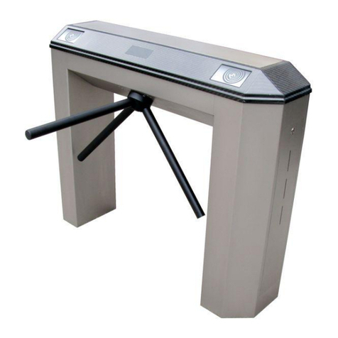
VOZROZHDENIE OXGARD CUBE C-05 User manual

VOZROZHDENIE LLC
OKPD 2 26.30.50.110
TU 26.30.50-007-33120038-2017
APPROVED BY
VZR.2515.001
TRIPOD TURNSTILE
CUBE C-05,С-05-2R MODEL
VZR.2515.001IM
INSTALLATION MANUAL
40 sheets
2021

VZR.2515.001IM
CUBE C-05 tripod turnstile
Installation Manual
2
TABLE OF CONTENTS
1General instructions....................................................................................................................... 4
2Safety precautions.......................................................................................................................... 5
3Preparing the product for installation ........................................................................................... 6
3.1 Procedure for transporting the product to the installation place .............................................. 6
3.2 Rules for unpacking the product............................................................................................. 6
3.3 Rules for visual inspection of the product ............................................................................... 6
3.4 Product installation place requirements.................................................................................. 8
3.5 Procedure for checking compliance of the installation place................................................... 9
4Product installation and dismantling........................................................................................... 11
4.1 Equipment required.............................................................................................................. 11
4.2 Product installation............................................................................................................... 11
4.3 Dismantling the product........................................................................................................ 17
5Connecting and setting the product............................................................................................ 18
5.1 Power connection................................................................................................................. 22
5.2 Control panel connection...................................................................................................... 24
5.3 Access control and management system connection (optional)............................................ 27
5.4 Control panel connection to the ACS controller .................................................................... 31
6Comprehensive inspection .......................................................................................................... 36
6.1 Visual inspection and verification of the product readiness for use....................................... 36
7Acceptance of the installed product............................................................................................ 37
APPENDIX A —Brief description of CAN2.0 data bus...................................................................... 38
APPENDIX B —Turnstile connection diagram.................................................................................. 39

VZR.2515.001IM
CUBE C-05 tripod turnstile
Installation Manual
3
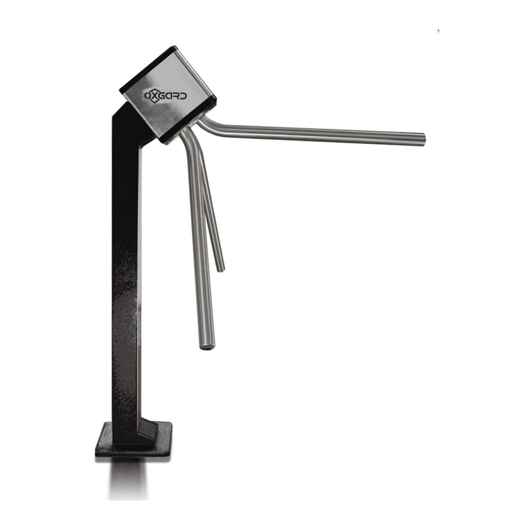
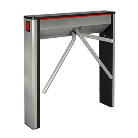
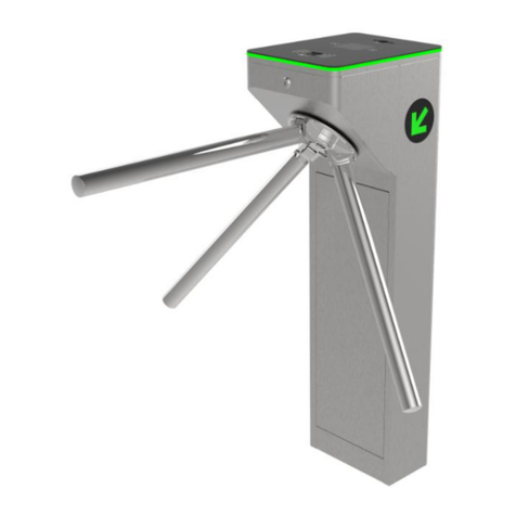
This Installation Manual (IM) applies to Oxgard CUBE C-05,C05-2R tripod
turnstile and its variants (hereinafter referred to as the product). Product firmware
version: FW С-10
Design variants:
C-05 –Electromechanical tripod turnstile.
С-05-2R electromechanical tripod turnstile + reader 2 pcs.
IM defines rules and a procedure for installation and commissioning of the
product.
Before installing the product, please read the Operation Manual
VZR.2515.001 OM as well.
Due to constant work on improving the product, changes to its design may
be made, which are not represented in this IM revision.
The following abbreviations are used in this document:
OM —Operation Manual;
IM —Installation Manual;
PSU —power supply unit;
CP—control panel symbol;
BCP 01 —basic control panel;
UCP 02 —universal control panel;
ACS —access control system;
SFAS —security and fire alarm system;
NC —normally closed connection;
NO —normally open connection.

VZR.2515.001IM
CUBE C-05 tripod turnstile
Installation Manual
4
1 GENERAL INSTRUCTIONS
For general safety when assembling and installing the product, take into
account all the recommendations and instructions contained herein.
Before starting installation work, completely de-energize the product.
DO NOT:
INSTALL THE POWER SUPPLY UNIT INSIDE THE TURNSTILE
HOUSING AS IT MAY RESULT IN ELECTRIC SHOCK TO PERSONS.
INSTALL THE TURNSTILE OUTSIDE DRY AND HEATED ROOMS.
PREVENT OR ACCELERATE MOVEMENT OF THE TURNSTILE ARMS.
APPLY PASTES AND LIQUIDS CHEMICALLY AGGRESSIVE TO
MATERIALS OF THE HOUSING WHEN CLEANING THE PRODUCT.

VZR.2515.001IM
CUBE C-05 tripod turnstile
Installation Manual
5
2 SAFETY PRECAUTIONS
Installation should be carried out with observance of “Regulations for
Operation of Consumer Electrical Installations” and “Safety Regulations for
Operation of Consumer Electrical Installations”.
The product shall only be installed by qualified personnel trained in
handling of electrical devices and instructed on safety precautions when handling
the electrical installations with voltages of up to 1000V.
ATTENTION: FAILURE TO COMPLY WITH THE SAFETY
REQUIREMENTS SPECIFIED IN THIS SECTION CAN RESULT IN DEATH AND
DAMAGE TO HEALTH, COMPLETE OR PARTIAL LOSS OF PERFORMANCE
OF THE PRODUCT AND/OR AUXILIARY EQUIPMENT.
ATTENTION: MANUFACTURER WAIVES ANY RESPONSIBILITY
FOR DEATH AND DAMAGE TO HEALTH, COMPLETE OR PARTIAL LOSS OF
PERFORMANCE OF THE PRODUCT AND/OR AUXILIARY EQUIPMENT IF
USER FAILS TO COMPLY WITH THE SAFETY REQUIREMENTS SPECIFIED
IN THIS SECTION, AND ALSO VOIDS THE PRODUCT WARRANTY.

VZR.2515.001IM
CUBE C-05 tripod turnstile
Installation Manual
6
3 PREPARING THE PRODUCT FOR INSTALLATION
3.1 Procedure for transporting the product to the installation place
The product in the original package can be transported without range
limitation by air, enclosed road and rail transport provided it is protected against
direct exposure to precipitation and dust.
In order to avoid moisture condensation after transportation at subzero
temperatures, the product shall be pre-held in a room with normal climatic
conditions for 12 hours.
Loading and unloading operations should be carried out in compliance with
safety regulations.
3.2 Rules for unpacking the product
3.2.1 Perform visual inspection of the packaging. There should be no
visible damage on the package.
3.2.2 Open the transportation box, unpack and check completeness of
the product:
1) turnstile stand;
2) CP with cable;
3) base cover.
4) barrier arms
3.3 Rules for visual inspection of the product
3.3.1 Check completeness of the product.
Completeness shall be checked according to the Logbook VZR.2515.001 LB.

VZR.2515.001IM
CUBE C-05 tripod turnstile
Installation Manual
7
3.3.2 Visually inspect the product. There should be no visible damage
on the product.
3.3.3 If any damage is found, prepare a Claim Report.
3.3.4 Figure 1 –overall dimensions of the turnstile.
Figure 1 –Overall dimensions of the turnstile

VZR.2515.001IM
CUBE C-05 tripod turnstile
Installation Manual
8
3.4 Product installation place requirements
ATTENTION: TO AVOID WAVING AND/OR OVERTURNING DURING
OPERATION, INSTALL THE TURNSTILE SECURELY. IN CASE OF PRODUCT
INSTALLATION ON LOW STRENGTH FLOOR - TAKE MEASURES FOR
FLOORS STRENGTHENING IN THE PLACE OF INSTALLATION.
Figure 2 –when installing the turnstile, it is necessary to consider the
possible free travel of the barrier arm (it makes 6 degrees on each side in STOP
mode).

VZR.2515.001IM
CUBE C-05 tripod turnstile
Installation Manual
9
Figure 2 –Possible free travel of the barrier arm in "STOP" mode
3.5 Procedure for checking compliance of the installation place
ATTENTION: THE PASSAGE ZONES SHALL BE ARRANGED TO
ALLOW RECORDING OF PASSAGES DURING TURNSTILE OPERATION
UNDER ACS CONTROL AND TO AVOID UNAUTHORIZED PASSAGES.

VZR.2515.001IM
CUBE C-05 tripod turnstile
Installation Manual
11
4 PRODUCT INSTALLATION AND DISMANTLING
4.1 Equipment required
Equipment to be used for the turnstile installation:
1) electric perforating machine
2) 12 mm carbide drill bit for drilling anchor holes in the floor (we recommend to use the
anchor with the screw of the FHII 12/15 SK type);
3) S5 key for the screws with an internal hexagon;
4) slot head screwdriver;
5) plumb or level;
6) steel shims for turnstile leveling;
7) round file;
8) side-cutting pliers.
4.2 Product installation
ATTENTION: CAREFULLY READ THIS SECTION OF THE MANUAL
BEFORE INSTALLING THE PRODUCT
4.2.1 Prepare a horizontal area at the product installation site.
4.2.2 Prepare a chase or cable conduit going from the site to the place
of installation of the PSU, CP and, where necessary, to the ACS and SFAS
connection point.

VZR.2515.001IM
CUBE C-05 tripod turnstile
Installation Manual
12
4.2.3 Turnstile installation site:
Figure 4 –prepare 3 holes (12 mm in diameter) in the floor for the turnstile
stand anchors according to the installation dimensions.
Position of mounting holes relative to the external dimensions of the
turnstile is shown in Appendix B.
The depth of the embedded hole is 120 mm, it should exceed the anchor
length by 5 mm. Insert anchors into the holes.

VZR.2515.001IM
CUBE C-05 tripod turnstile
Installation Manual
13
Figure 4 –Installation dimensions of the turnstile site

VZR.2515.001IM
CUBE C-05 tripod turnstile
Installation Manual
14
4.2.4 Figure 4 –cable routing is exercised through hole (1) at the
lower turnstile stand plate.
4.2.5 Lay the CP connection cable, PSU cable and, if provided, the
ACS and SFAS cables in the cable conduit or chase.
4.2.6 Install the turnstile stand onto the prepared site.
4.2.7 Insert cables from the CP, PSU, ACS and SFAS cables into the
turnstile housing, after passing them into the turnstile stand. Secure the cables
with cable ties.
4.2.8 Align the holes in the turnstile stand with the floor anchors
(Figure 5 –1).
Check turnstile verticality in 2 planes, if necessary, use steel shims of
required thickness for the turnstile correct installation.

VZR.2515.001IM
CUBE C-05 tripod turnstile
Installation Manual
15
Figure 5 –Preparation to install the turnstile
Fix the turnstile stand with three screws (Figure 5 –2) by screwing them
into the appropriate anchors using S5 key for the screws with an internal hexagon.
Secure the base cover with the double-sided adhesive tape.
Install the barrier arm assembly on the turnstile base
(Figure 6 –1)

VZR.2515.001IM
CUBE C-05 tripod turnstile
Installation Manual
16
Figure 6 –Barrier arm assembly mounting.
4.2.9 Remove the protective film from the turnstile housing.

VZR.2515.001IM
CUBE C-05 tripod turnstile
Installation Manual
17
4.3 Dismantling the product
4.3.1 Dismantle the product as follows for sending it for calibration or
repair:
1) turn the product power off;
2) disconnect the product from power supply;
3) disconnect the product cable part from auxiliary cables;
4) dismantle the barrier arm assembly
5) dismantle the product from the installation pad.
4.3.2 Before packing, clean the product from dust and dirt.
4.3.3 Put the product in the packing box.

VZR.2515.001IM
CUBE C-05 tripod turnstile
Installation Manual
18
5 CONNECTING AND SETTING THE PRODUCT
Connection of the PSU, CP and ACS is carried out using the control board
located in the block of barrier arms under the safety enclosure.
To conveniently connect the turnstile and get access to all necessary
contacts, the turnstile should be partially disassembled. This scope of works
includes dismantling of the safety enclosure.
To do this, unscrew the four screws (Figure 7 –1) and gently slide the
enclosure upwards, taking care not to break the cables inside the protective
enclosure.

VZR.2515.001IM
CUBE C-05 tripod turnstile
Installation Manual
19
Figure 7 –Dismounting of the turnstile safety enclosure
Slide the enclosure till the end and free access to the rotation mechanism.
Figure 8 –the appearance of the control board and layout of the
connectors for connecting the PSU, CP, ACS and SFAS is shown.

VZR.2515.001IM
CUBE C-05 tripod turnstile
Installation Manual
20
Figure 8 –Appearance of the turnstile control board
Figure 8 –The turnstile operating modes are set using the BUT button.
To select the required turnstile mode, it is necessary:
- press and hold the BUT button until a short beep. The turnstile operating
mode is selected based on the number of short beeps.
- it is necessary to release the BUT button after the required number of
signals, a long beep, which indicates that the desired mode has been written into
the controller memory, will sound.
- when the power is off, the selected mode is not reset.
This manual suits for next models
1
Table of contents