VRG Controls VPC SN Series User manual

VRG CONTROLS LLC. 1 of 36 JUNE 2021
VPC “SN” SERIES VALVE PILOT CONTROLLERS
INSTRUCTION MANUAL
VRG Controls LLC. 1 of 35 JANUARY 2019
Applicable Models:
ADDRESS:
TOLL FREE:
E-MAIL
WEBSITE:
STAY IN TOUCH!
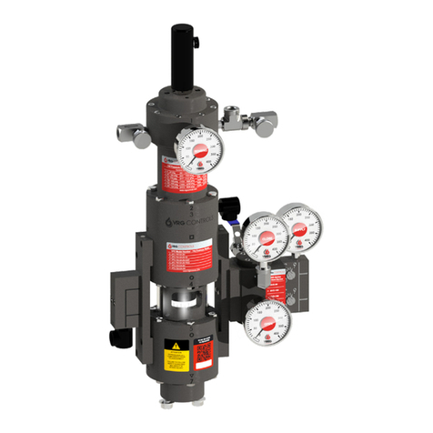
VPC “SN” SERIES VALVE PILOT CONTROLLER
INSTRUCTION MANUAL
PATENT NO.:
US 9,400,060 B2
VPC PED ATEX Tag - Proof 3
Extreme-Tough
3.05” x 1.84”
PATENT NO.:
US 9,400,060 B2
US 10,234,047 B2
PATENT NO:
US D919763S1
US 10876645
US 10234047B2
US 9400060B2

VRG CONTROLS LLC. 2 of 36 JUNE 2021
VPC “SN” SERIES VALVE PILOT CONTROLLERS
INSTRUCTION MANUAL
VPC “SN” SERIES VALVE PILOT CONTROLLERS
INSTRUCTION MANUAL
VRG Controls LLC. 2 of 35 JANUARY 2019
DESCRIPTION PAGE
Scope of Manual 3
Technical Assistance 3
Applicable Models 4
Descripon 4
VPC Valve Pilot Controller Technical Specicaons 5
Model Number Explanaon 6
VPC Controller Spring Ranges and Performance Specicaons 7
Flow Calculaons 8
How It Works Descripons 9
VPC-DA-SN (Seat & Nozzle Type) Inial Adjustment Procedure Summary 10
VPC-DA-SN (Seat & Nozzle Type) Applicaon Based Fine Tuning Seng Guidelines 11
VPC-DA-SN (Seat & Nozzle Type) Assembly Conguraon Summary 12
VPC-DA-SN Assembly Guides 13-15
Factory Quality Checklist VPC Valve Pilot Controller 16
VPC-SN Series Repair Kit BIll of Materials Packing List 17
VPC-DA-SN Pilot Annual Maintenance Checklist 18
VPC Applicaon Schemacs Table of Contents 19
VPC-DA-SN Applicaon Schemacs 20-35
TABLE OF CONTENTS
and Volume Booster

VRG CONTROLS LLC. 3 of 36 JUNE 2021
VPC “SN” SERIES VALVE PILOT CONTROLLERS
INSTRUCTION MANUAL
VRG Controls LLC. 3 of 35 JANUARY 2019
VPC “SN” SERIES VALVE PILOT CONTROLLERS
INSTRUCTION MANUAL
SCOPE OF MANUAL
This Instrucon Manual provides instrucons
for installaon, maintenance, adjustment and
troubleshoong of VRG Controls VPC“SN” Series
Valve Pilot Controllers. This product is typically
ulized in conjuncon with control valves, pneumac
actuators and a variety of other ancillarydevices and
accessories. For informaon on products other than
those manufactured by VRG Controls, please consult
the appropriate manufacturer.
WARNING
VPC - Valve Pilot Controllers ulize high pressure
ammable natural gas or other pneumac supply
as part of their standard operaon. Improper
installaon, operaon, maintenance and adjustment
of these devices can result in property damage,
personal injury or death. Only those qualied through
training should install, operate, maintain or adjust
this product. Contact your local VRG Controls sales
representave or VRG Controls direct for addional
informaon or assistance.
TECHNICAL ASSISTANCE
For technical assistance with VRG products, please
contact your local VRG Controls sales representave
or VRG Controls direct. In order to facilitate technical
assistance, we strongly recommend that obtain the
MODEL NUMBER and SERIAL NUMBER of the product
for which you require assistance prior to contact us.
MODEL NUMBER and SERIAL NUMBER may be found
on the PRODUCT ID LABEL located on the front of the
VPC product on the center face of lower poron of
the power assembly.
We recommend that you record the MODEL NUMBER
and SERIAL NUMBER of all VRG Products installed at
each applicaon locaon in the table below for future
reference.
ITEM TAG MODEL NUMBER SERIAL NUMBER
1
2
3
4
5
6
7
8
Example Run 1 Monitor Regulator VPC-700-DA-SN 08125V
INSTALLED ITEM IDENTIFICATION LOG

VRG CONTROLS LLC. 4 of 36 JUNE 2021
VPC “SN” SERIES VALVE PILOT CONTROLLERS
INSTRUCTION MANUAL
VPC “SN” SERIES VALVE PILOT CONTROLLERS
INSTRUCTION MANUAL
VRG Controls LLC. 4 of 35 JANUARY 2019
DESCRIPTION
DEFINITIONS
APPLICATIONS
Applicable Models:

VRG CONTROLS LLC. 5 of 36 JUNE 2021
VPC “SN” SERIES VALVE PILOT CONTROLLERS
INSTRUCTION MANUAL
VRG Controls LLC. 5 of 35 JANUARY 2019
VPC “SN” SERIES VALVE PILOT CONTROLLERS
INSTRUCTION MANUAL
TABLE 1.0 VPC VALVE PILOT CONTROLLER TECHNICAL SPECIFICATIONS
NOTES
1. NC Balanced Valves and NO Seat & Nozzle internal
components may be exchange/converted to meet
applicaon requirements
2. ZERO Steady State emissions achieved when VPC
properly adjusted to exhibit factory advised deadband
seng
3. Consumpon is approximate and based upon 100
psig Supply Gas with #2 Adjustable Orice Sengs and
CLOSE and OPEN gages balanced at 80% Supply Gas
Dierenal at steady state. Atmosphere emissions may
be completely eliminated when Discharge to Pressure
System incorporated.
4. Double acng VPC’s require addion of NVD No-Vent
Deviceto achieve ZERO emissions at full open and full
closed
5. Double Acng Piston Actuators Equipped with Single
Acng VPC requires addional interface instrumentaon
such as pneumac posioner or pilot-operated trigger
valve (GAP).
PATENT NO.:
US 9,400,060 B2
3-1500 psig (21-10,341 kPa)
316 SS
(Viton Oponal)
Powder Coated

VRG CONTROLS LLC. 6 of 36 JUNE 2021
VPC “SN” SERIES VALVE PILOT CONTROLLERS
INSTRUCTION MANUAL
VPC “SN” SERIES VALVE PILOT CONTROLLERS
INSTRUCTION MANUAL
VRG Controls LLC. 6 of 35 JANUARY 2019
TABLE 2.0 MODEL NUMBER EXPLANATION
VPC MODEL NUMBER IDENTIFICATION LABEL
VPC SPRING CONTROL RANGE LABEL
VPC MODEL NUMBER IDENTIFICATION LABEL VPC SPRING CONTROL RANGE LABEL
* PRESSURE APPLYED CANNOT EXCEED 30 MINUTES
MODEL MAOP SPIKE PRESSURE * BURST PRESSURE
VPC-225 225 psig 450 psig 675 psig
VPC-700 700 psig 1050 psig 2100 psig
VPC-1500 1500 psig 2250 psig 3500 psig

VRG CONTROLS LLC. 7 of 36 JUNE 2021
VPC “SN” SERIES VALVE PILOT CONTROLLERS
INSTRUCTION MANUAL
VRG Controls LLC. 7 of 35 JANUARY 2019
VPC “SN” SERIES VALVE PILOT CONTROLLERS
INSTRUCTION MANUAL
TABLE 3.0 VPC CONTROLLER SPRING RANGES AND PERFORMANCE SPECIFICATIONS
NOTES
1. Setpoint Accuracy based upon proper maintenance of
VPC Controller and adjustment to specicaon following
VPC Controller Technical Manual. Setpoint Accuracy
represents maximum control band over 24 hours when
VPC ulized WITHOUT volume booster or pneumac
posioner. When VPC ulized WITH volume booster
or pneumac posioner accuracy increases and value
should be mulplied by 0.5.
2. Maximum “GAP” Setpoint Range applicable only to
VPC-GAP Controller Conguraons. The “GAP” relates
to bracketed high-low trigger points for discrete on-o
control logic.
3. These Control Springs not recommended for this
parcular model of VPC GAP Controller.

VRG CONTROLS LLC. 8 of 36 JUNE 2021
VPC “SN” SERIES VALVE PILOT CONTROLLERS
INSTRUCTION MANUAL
VPC “SN” SERIES VALVE PILOT CONTROLLERS
INSTRUCTION MANUAL
VRG Controls LLC. 8 of 35 JANUARY 2019
Variable Descripon Unit
Qc Crical Flow Across Inlet Orice sc
P1Supply Pressure psig
Cv Flow Factor --
GSpecic Gravity of Gas --
TGas Temperature *F
TABLE 4.0 CRITICAL FLOW EQUATION
Qc=312.9 X (P1+14.7) X Cv X 1
G X (T + 460)
Where:
TABLE 5.0 FLOW COEFFICIENT TABLE (CV)
Adjustable Orice Flow Coecients
Installed Orice 01234567
Standard 0.006 0.009 0.018 0.044 0.069 0.096 0.111 0.126
Medium (M) 0.042 0.045 0.062 0.089 0.134 0.172 0.211 0.249
Large (L) 0.042 0.063 0.172 0.328 0.461 0.578 0.634 0.675
Adjustable Orice Seng
Notes:
1. Equaon above may be ulized to determine supply regulator consumpon requirements and
steady state bleed rates for control valves operated with a VGP Valve Gas Posioner.
2. VGP Adjustable Orices are typically ulized in double acng applicaons only and represents
the liming ow factor in determining ow rates and resultant stroking mes.
3. When applicaons do not ulize Adjustable Orice, then the VGP internal Balanced Valve
becomes the liming factor to determine ow rates and resultant stroking mes. VGP Internal
Balanced Valve Cv=1.45.
Variable Descripon Unit
tStroke Time Sec.
HActuator Cylinder Stroke Length in.
D Actuator Cylinder Diameter in.
Cv Liming Flow Coecient --
GGas Specic Gravity Typ. 0.6 Natural Gas
TGas Temperature *F
TABLE 6.0 ESTIMATED TRAVEL TIME
Where:
t=0.148 X G
T + 460
H X D
Cv
2
X

VRG CONTROLS LLC. 9 of 36 JUNE 2021
VPC “SN” SERIES VALVE PILOT CONTROLLERS
INSTRUCTION MANUAL
VRG Controls LLC. 9 of 35 JANUARY 2019
VPC “SN” SERIES VALVE PILOT CONTROLLERS
INSTRUCTION MANUAL
HOW IT WORKS DESCRIPTIONS:
DOUBLE ACTING VPC-DA-SN
When the SENSING pressure is equal to the VPC-DA-SN
setpoint, the net force on the VPC-DA-SN power module is
zero. This is the equilibrium or “balanced” condion where
the sensing pressure that pushes down on the sensing
diaphragm and the control spring force that pulls up on the
sensing diaphragm are equal. When the VPC-DA-SN achieves
equilibrium, the OPEN seat & nozzle assembly and CLOSE
seat & nozzle assembly will be posioned at equal openings
maintaining a constant OUTPUT pressure to the top and
boom chambers of the control valve actuator. The VPC-DA-
SN will exhibit constant emissions at this state as referenced in
Table 1.0. From this posion two possible scenarios can occur,
the sensing pressure can rise above or below the set point.
If the sensing pressure rises above the VPC-DA-SN setpoint
the net force on the VPC-DA-SN power module is downward.
The CLOSE seat & nozzle assembly will move toward closed
posion and divert pressure to the CLOSE chamber of the
double acng actuator. The OPEN seat & nozzle assembly will
open more and pressure shall be reduced on the OPEN side of
the double acng actuator. The combinaon of these acons
creates a dierenal pressure to be applied to the double
acng actuator that will move the valve toward the closed
posion.
If the sensing pressure falls below the VPC-DA-SN setpoint
the net force on the VPC-DA-SN power module is upward.
The OPEN seat & nozzle assembly will move toward closed
posion and divert pressure to the OPEN chamber of the
double acng actuator. The CLOSE seat & nozzle assembly
will open more and pressure shall be reduced on the CLOSE
side of the double acng actuator. The combinaon of these
acons creates a dierenal pressure to be applied to the
double acng actuator that will move the valve toward the
open posion.
An adjustment for sensivity is achieved via a rotang drum
at the center of the VPC-DA-SN. Rotaon of the drum to the
LEFT (Increasing Numbers) will increase the xed distance of
the internal assembly, requiring greater travel of VPC-DA-SN
internals to aect a change in CLOSE PRESSURE and OPEN
PRESSURE. Conversely, rotaon of the drum to the RIGHT
(Decreasing Numbers) will decrease the xed distance of
the internal assembly, requiring lesser travel of VPC-DA-SN
internals to aect a change in CLOSE PRESSURE and OPEN
PRESSURE.
Adjustable orices are installed upstream of the SUPPLY
PRESSURE that aect the maximum achievable ow rate to
CLOSE PRESSURE and OPEN PRESSURE independently. These
Adjustable Orices may be ulized to adjust the CLOSING and
OPENING speed of travel of the control valve actuator with
both Adjustable Orices being set equally. Alternavely, the
Adjustable Orices may be set at dierent levels to achieve a
dierence between CLOSING and OPENING speed necessary
to opmize control performance for certain applicaons.
Note that the VPC-DA-SN atmospheric emissions may be
completely eliminated by discharging exhaust to a nearby
or downstream pressure system. Addionally, addion of
an NVD No-Vent Device will eliminate emissions when the
control valve remains in the full-open or full-closed posions
such as a standby, overpressure monitor or relief type
applicaon.

VRG CONTROLS LLC. 10 of 36 JUNE 2021
VPC “SN” SERIES VALVE PILOT CONTROLLERS
INSTRUCTION MANUAL
VPC “SN” SERIES VALVE PILOT CONTROLLERS
INSTRUCTION MANUAL
VRG Controls LLC. 10 of 35 JANUARY 2019
TABLE 7.0 VPC DA-SN (SEAT AND NOZZLE TYPE) INITIAL ADJUSTMENT PROCEDURE SUMMARY
NOTES
1. Adjustment and Installaon of VRG Controls
equipment should be only be performed by qualied
personnel adequately trainedand familiar with products.
2. For technical assistance, please contact your local VRG
Controls Sales Representave or VRG Controls direct
(www.vrgcontrols.com)
STEP VPC COMPONENT ADJUSTMENT ACTION OR OBSERVATION NOTES
1SENSING PRESSURE CLOSE + VENT SENSING VALVES must be 100% bub-
ble ght for successful adjustment
2OUTPUT VALVES CLOSE OUTPUT VALVES must be 100% bub-
ble ght for successful adjustment
3SUPPLY REGULATOR Adjust to Required Pressure Refer to ACTUATOR Manufacturer
Details for required SUPPLY PRES-
SURE
4SETPOINT ADJUST SCREW → CCW to unload Control Spring
Then Clockwise ← 2.0 Turns
When CONTROL SPRING unloaded
torque will decrease noceably
5ADJUST DRUM → RIGHT unl STOP • then ← 1 Turns to ← LEFT Do not apply excessive force
6SENSING PRESSURE Apply Required Setpoint Pressure (False Signal) Recommended to ulize accurate
calibrated gage
7SETPOINT ADJUST SCREW Clockwise ← (CW) unl CLOSE PRESSURE
And OPEN PRESSURE are EQUAL regardless of value.
CLOSE and OPEN Pressures should
be steady.
8ADJUST DRUM Turn to ← LEFT (Increasing Numbers) unl either the
CLOSE OR OPEN OUTPUT decreases to TARGET BALANCE
PRESSURE Per Table 8.0.
CLOSE and OPEN OUPUT pressures
may not increase at the same rate.
Rotate drum to raise or lower out-
put pressure.
9SETPOINT ADJUST SCREW Turn clockwise ← (CW) OR counterclockwise → (CCW)
unl CLOSE PRESSURE and OPEN PRESSURE are EQUAL
regardless of value.
Rotate back & forth to achieve
Equal pressures
10 OUTPUT PRESSURE OUTPUT PRESSURE Should be steady at TARGET BAL-
ANCE PRESSURE Per Table 8.0.
REPEAT Steps 9 and 10 Unl this scenario is achieved.
11 EXHAUST EXHAUST port should vent gas connually at this stage
when CLOSE PRESSURE and OPEN PRESSURE are equal.
If the VPC is equipped with an NVD No-Vent Device the
VPC will exhibit ZERO vent (exhaust) when control valve
is FULL OPEN or FULL CLOSED and process operang
pressure is within ±2.0% maximum spring range value
from setpoint.
Inial Adjustment Achieved. Refer
to Applicaon Based Fine Tuning
Seng Guidelines (Table 8.0) for Ap-
plicaon Specic Secondary Tuning.

VRG CONTROLS LLC. 11 of 36 JUNE 2021
VPC “SN” SERIES VALVE PILOT CONTROLLERS
INSTRUCTION MANUAL
VRG Controls LLC. 11 of 35 JANUARY 2019
VPC “SN” SERIES VALVE PILOT CONTROLLERS
INSTRUCTION MANUAL
TABLE 8.0 VPC-DA-SN (SEAT AND NOZZLE TYPE) APPLICATION BASED FINE TUNING SETTING
GUIDELINES
NOTES
1. Adjustment and Installaon of VRG Controls equipment should be only
be performed by qualied personnel adequately trainedand familiar with
products.
2. For technical assistance, please contact your local VRG Controls Sales
Representave or VRG Controls direct (www.vrgcontrols.com).
3. All values represent astarng point. Dynamic tuning with VPC in “live
control” will be necessary to opmize performance.
4. In this table,Pipeline Interconnects are dened >1.0 mile downstream
piping adjacent to control valve.
5. In this table, Close-Coupled System Applicaons are dened <1.0mile
downstream pipingadjacent to control valve.
6. Increasing number on theSUPPLY & EXHAUST ORIFICE will increase
the speed of responseindependently in each direcon (faster reset rate).
Refer to VPC Applicaon Schemac to determine which Adjustable Orice
controls OPEN and CLOSE speed.
7. If system is unstable upon adjusng VPC per above guidelines, correcve
adjustment to INCREASE CLOSING speed and REDUCE OPENING speed
are suggested. Addionally, the sensivity may be decreased by increasing
the output pressure of CLOSE/OPEN gages from 50% of SUPPLY GAS
PRESSURE up to 99% by rotang ADJUSTMENT DRUM to right in direcon
of decreasing numbers.
8. All above sengs are for ACTIVE control valves. For STANDBY Monitor
Type control valves, it is recommended that the CLOSE ORIFICE that
controls CLOSING SPEED be increased to maximum seng of #6 in all cases.
See applicaon schemac for details.
9. For Close-Coupled System Applicaons where “Discharge to Pressure
System” is incorporated, PDischarge must not exceed 150 psig
10. Typically PDierenal = PSupply –PDischarge must be minimum of 100
psid. Where PDierenal < 100 psig, pleases consult VRG Controls
Actuator Volume Any
M5 (.80
S2 M5 (.90
S2 M5 (.90
S2 S3
N
N.90g
1. Adjustment and Installaon of VRG Controls equipment should be only
be performed by qualied personnel adequately trained and familiar with
products.
2. For technical assistance, please contact your local VRG Controls Sales
Representave or VRG Controls direct (www.vrgcontrols.com).
3. All values represent a starng point. Dynamic tuning with VPC in “live
control” will be necessary to opmize performance.
4. In this table, Pipeline Interconnects are dened >1.0 mile downstream
piping adjacent to control valve.
5. In this table, Close-Coupled System Applicaons are dened <1.0 mile
downstream piping adjacent to control valve.
6. Increasing number on the CLOSE and OPEN Orice will increase the
speed of response independently in each direcon (faster reset rate).
Refer to VPC Applicaon Schemac to determine which Adjustment Orice
controls OPEN and CLOSE speed.
7. If system is unstable upon adjusng VPC per above guidelines, correcve
adjustment to INCREASE CLOSING speed and REDUCE OPENING speed are
suggested. Addionally, the sensivity may be decreased by increasing the
output pressure of CLOSE/OPEN gages from 50% of SUPPLY GAS PRESSURE
up to 99% by rotang ADJUSTMENT DRUM to right in direcon of decreasing
numbers.
8. All above sengs are for ACTIVE control valves. For STANDBY Monitor
Type control valves, it is recommended that the CLOSE ORIFICE that controls
CLOSING SPEED by increasing to maximum seng of #6 in all cases.
See applicaon schemac for details.
9. For Close-Coupled System Applicaons where “Discharge to Pressure
System” is incorporated, PDischarge must not exceed 150 psig.
10. Typically PDierenal = PSupply - PDischarge must be minimum of 100
psid. Where PDierenal < 100 psig, pleases consult VRG Controls.

VRG CONTROLS LLC. 12 of 36 JUNE 2021
VPC “SN” SERIES VALVE PILOT CONTROLLERS
INSTRUCTION MANUAL
VPC “SN” SERIES VALVE PILOT CONTROLLERS
INSTRUCTION MANUAL
VRG Controls LLC. JANUARY 2019
1. When VPC-DA-SN discharges to a pressure system the
EXHAUST “EX” manifold must be replaced with full capacity
DOWNSTREAM DISCHARGE “DN” manifold.
Output DA
Internal Valve Logic SN
Acon --
Cartridge Top Flange 1
Spring Cartridge 2
700 Sensing Spacer 3
225/1500 Spacer Flange/
Adapter
3A
225/1500 Sensing Spacer 3B
Pilot Block (TOP) TRIANGLE
Pilot Block (BOTTOM) CIRCLE
Pilot Spacer (TOP) 4
Pilot Spacer (BOTTOM) 5
Pilot Block (TOP) CIRCLE
Pilot Block (Boom) RECTANGLE
Pilot Boom Flange 7
Le Hand Manifold DA “S”
Right Hand Manifold DA “EX”
DA Output Manifold “OUT 1” “OUT 2”
TABLE 11.0 APPLICATION BASED FINE TUNING SETTING GUIDELINES – VPC DOUBLE ACTING
(-1/4)
(-1/4)
(-1/4)
NOTES
1. For ACTUATOR VOLUME greater than 950 in3
NOTES
VOLUME BOOSTER
IN
OUT
BOOSTER
SENSITIVITY
ADJUSTMENT
VPC “SN” SERIES VALVE PILOT CONTROLLERS
INSTRUCTION MANUAL
VRG Controls LLC. JANUARY 2019
1. When VPC-DA-SN discharges to a pressure system the
EXHAUST “EX” manifold must be replaced with full capacity
DOWNSTREAM DISCHARGE “DN” manifold.
Output DA
Internal Valve Logic SN
Acon --
Cartridge Top Flange 1
Spring Cartridge 2
700 Sensing Spacer 3
225/1500 Spacer Flange/
Adapter
3A
225/1500 Sensing Spacer 3B
Pilot Block (TOP) TRIANGLE
Pilot Block (BOTTOM) CIRCLE
Pilot Spacer (TOP) 4
Pilot Spacer (BOTTOM) 5
Pilot Block (TOP) CIRCLE
Pilot Block (Boom) RECTANGLE
Pilot Boom Flange 7
Le Hand Manifold DA “S”
Right Hand Manifold DA “EX”
DA Output Manifold “OUT 1” “OUT 2”

VRG CONTROLS LLC. 13 of 36 JUNE 2021
VPC “SN” SERIES VALVE PILOT CONTROLLERS
INSTRUCTION MANUAL
VRG Controls LLC. 13 of 35 JANUARY 2019
VPC “SN” SERIES VALVE PILOT CONTROLLERS
INSTRUCTION MANUAL
VPC-700-DA-SN (Double Acng) Assembly Guide
Part Number: PA-0020
Corresponds with Diagrams 1 and 1A
VPC-700-DA-SN-NVD(Double Acng) Assembly Guide
With NVD No-Vent Device
Part Number: PA-0025
Corresponds with Diagrams 2, 2A, 3, AND 3A

VRG CONTROLS LLC. 14 of 36 JUNE 2021
VPC “SN” SERIES VALVE PILOT CONTROLLERS
INSTRUCTION MANUAL
VPC “SN” SERIES VALVE PILOT CONTROLLERS
INSTRUCTION MANUAL
VRG Controls LLC. 14 of 35 JANUARY 2019
VPC-700-DA-SN-DN (Double Acng) Assembly Guide
Part Number: PA-0020-DN
Corresponds with Diagrams 3, 3A, 4 and 4A
VPC-700-DA-SN-DN-NVD (Double Acng) Assembly
Guide With NVD No-Vent Device
Part Number: PA-0025-DN
Corresponds with Diagrams 5 and 5A

VRG CONTROLS LLC. 15 of 36 JUNE 2021
VPC “SN” SERIES VALVE PILOT CONTROLLERS
INSTRUCTION MANUAL
VRG Controls LLC. 15 of 35 JANUARY 2019
VPC “SN” SERIES VALVE PILOT CONTROLLERS
INSTRUCTION MANUAL
VPC-1500-DA-SN(Double Acng) Assembly Guide
Part Number: PA-0022-NO
Corresponds with Diagrams 6 and 6A
VPC-1500-DA-SN-NC (Double Acng) Assembly
Guide With NVD No-Vent Device
Part Number: PA-0022-NC
Corresponds with Diagrams 7 and 7A

VRG CONTROLS LLC. 16 of 36 JUNE 2021
VPC “SN” SERIES VALVE PILOT CONTROLLERS
INSTRUCTION MANUAL

VRG CONTROLS LLC. 17 of 36 JUNE 2021
VPC “SN” SERIES VALVE PILOT CONTROLLERS
INSTRUCTION MANUAL
VRG Controls LLC. 17 of 35 JANUARY 2019
VPC “SN” SERIES VALVE PILOT CONTROLLERS
INSTRUCTION MANUAL
TYPE
1EL-0010 Diaphragm w/Hole-700 psig, Buna Diaphragms 5
2EL-0020 Diaphragm w/Hole-1500 psi, Buna Diaphragms 1
3EL-0030 Diaphragm w/Hole-225 psig, Buna Diaphragms 1
4 EL-0200 O-Ring,-010, Buna, 3/8 x ¼ x 1/16 O-Rings 6
5 EL-0210 O-Ring,-012, Buna, ½ x 3/8 x 1/16 O-Rings 11
6 EL-0220 O-Ring,-014, Buna, 5/8 x 1/2 x1/16 O-Rings 4
7 EL-0230 O-Ring,-109, Buna, ½ x 5/16 x 3/32 O-Rings 1
8EL-0235 O-Ring,-112, Buna, 11/16 x ½ x3/32 O-Rings 4
9EL-0237 O-Ring,-116, Buna, 15/16 x ¾ x 3/32 O-Rings 1
10 EL-0240 O-Ring,-147, Buna, 2-7/8 x 2-11/16 x 3/32 O-Rings 2
11 EL-0100 Buna-N Seat Seals 2
12 N/A Mobilith SHC 220 Standard VRG Lubricant Lubricant 1
8

VRG CONTROLS LLC. 18 of 36 JUNE 2021
VPC “SN” SERIES VALVE PILOT CONTROLLERS
INSTRUCTION MANUAL
VPC “SN” SERIES VALVE PILOT CONTROLLERS
INSTRUCTION MANUAL
VRG Controls LLC. 18 of 35 JANUARY 2019
VPC-SN Double Acng Pilot Annual Maintenance Checklist
1. ________ VRG Controls recommends funconal inspecon of VPC-DA-SN Valve Pilot Controllers on an annual
basis.
2. ________ For operang regulators, VRG Controls recommends complete replacement of elastomers of VPC-DA-
SN Valve Pilot Controllers on a 5 year basis using VRG Controls repair kit.
3. ________For monitor or standby regulators, VRG Controls recommends complete replacement of elastomers of
VPC-DA-SN Valve Pilot Controllers on a 10 year basis using VRG Controls repair kit.
4. ________Isolate and remove pressure from all VPC-DA-SN components. Clean and inspect Adjustable Orice
Assemblies. Repressurize as appropriate
5. ________ Check Integrity of VPC-DA-SN Pilot Seats by increasing/decreasing measured variable (SENSING) at
least 2.0% of CONTROL SPRING RANGE above/below the setpoint such that full dierenal pressure is achieved on
CLOSE/OPEN gages. The EX port must be bubble ght.
6. ________ Soap Test All Diaphragm Mang Surfaces And Adjustable Orice Assembly to Check for Leaks.
7. ________ Replace Elastomers Ulizing VRG Controls VPC-DA-SN Series Repair Kit if leaks are found. See the
AssemblyManual for the VPC-DA-SN Series Valve Pilot Controller.
8. ________ Conrm Supply Pressure Is Correct. Refer To Original VRG Controls Packing Slip or Invoice for Details.
Also reference Table 6.0 - Applicaon Based Fine Tuning Seng Guidelines – VPC “SN” Series Double Acng (VPC-
DA-SN). If you cannot locate original packing slip or invoice to obtain original applicaon, informaon, please
contact VRG Controls or your local VRG Controls sales representave for assistance. PLEASE PROVIDE VPC SERIAL
NUMBER TO FACILITATE ASSISTANCE.
9. ________ Check sensivity of VPC-DA-SN. Conrm proper cylinder balance pressures (OPEN / CLOSE Gages)
10. ________Observe Operaon Of All Gages And Replace If Defecve.
11. ________Perform Internal Fricon Test by slightly tapping the VPC assembly when unit is adjusted to setpoint
and measured variable (SENSING) is loaded to setpoint pressure. CLOSE and OPEN gages should be equal and
steady when VPC is adjusted to setpoint. CLOSE and OPEN gages should remain stable and not move when VPC
assembly is tapped. Any change in CLOSE and/or OPEN gage values indicates internal fricon in the VPC.
12. ________ Inspect And Verify Proper Operaon Of All VPC-DA-SN Accessories.
Note: It is not necessary to replace any elastomers in VRG Controls instrumentaon or instrumentaon
accessories on a regular basis. Industry best pracces promote rebuild using a VRG Controls spare parts kit on
a 5-year frequency. VRG Controls suggested maintenance frequency should never supersede any mandated
regulatory requirements or company mandated maintenance.
(The pilot must have NVD in order to perform this test)
(Refer to Table 8.0)

VRG CONTROLS LLC. 19 of 36 JUNE 2021
VPC “SN” SERIES VALVE PILOT CONTROLLERS
INSTRUCTION MANUAL
VRG Controls LLC. 19 of 35 JANUARY 2019
VPC “SN” SERIES VALVE PILOT CONTROLLERS
INSTRUCTION MANUAL
TABLE 12.0 VPC APPLICATION SCHEMATICS TABLE OF CONTENTS
No. VPC Applicaon Actuator Mode Booster Accessory Discharge Pg.
1VPC-DA-SN PIPELINE DOUBLE ACTING - - ATM 20
1A VPC-DA-SN PIPELINE DOUBLE ACTING - VMO ATM 21
2VPC-DA-SN PIPELINE DOUBLE ACTING 2 BOOSTERS NVD ATM 22
2A VPC-DA-SN PIPELINE DOUBLE ACTING 2 BOOSTERS NVD AND VMO ATM 23
3VPC-DA-SN POWER PLANT DOUBLE ACTING 2 BOOSTERS NVD ATM 24
3A VPC-DA-SN POWER PLANT DOUBLE ACTING 2 BOOSTERS NVD AND VMO ATM 25
4VPC-DA-SN PIPELINE AND
POWER PLANT
DOUBLE ACTING - - PRESSURE SYSTEM 26
4A VPC-DA-SN PIPELINE AND
POWER PLANT
DOUBLE ACTING - VMO PRESSURE SYSTEM 27
5VPC-DA-SN PIPELINE AND
POWER PLANT
DOUBLE ACTING - NVD PRESSURE SYSTEM 28
5A VPC-DA-SN PIPELINE AND
POWER PLANT
DOUBLE ACTING - NVD AND VMO PRESSURE SYSTEM 29
6VPC-DA-SN PIPELINE AND
POWER PLANT
DOUBLE ACTING - NVD AND
BP SENSOR
PRESSURE SYSTEM 30
6A VPC-DA-SN PIPELINE AND
POWER PLANT
DOUBLE ACTING - NVD, BP SEN-
SOR, AND VMO
PRESSURE SYSTEM 31
7VPC-DA-SN PIPELINE NORMALLY OPEN 2 BOOSTERS SP SENSOR ATM 32
7A VPC-DA-SN PIPELINE NORMALLY OPEN 2 BOOSTERS SP SENSOR AND
VMO
ATM 33
8VPC-DA-SN PIPELINE NORMALLY CLOSED 2 BOOSTERS SP SENSOR ATM 34
8A VPC-DA-SN PIPELINE NORMALLY CLOSED 2 BOOSTERS SP SENSOR AND
VMO
ATM 35
DP
DP
DP
DP

VRG CONTROLS LLC. 20 of 36 JUNE 2021
VPC “SN” SERIES VALVE PILOT CONTROLLERS
INSTRUCTION MANUAL
VPC “SN” SERIES VALVE PILOT CONTROLLERS
INSTRUCTION MANUAL
VRG Controls LLC. 20 of 35 JANUARY 2019
No. VPC Applicaon Actuator Mode Booster Accessory Discharge
1 VPC-DA-SN Pipeline Double Acng - - ATM
P2 P1
FLOW
P1
P2
CLOSE
OPEN
CLOSE
Control Valve w/
Double Acng Actuator
SENSING
EX
VPC Port ID
Other Port ID
Gage Label
Pneumac Connecon
Adjustment Tag Line
TEXT
TEXT
TEXT
SCHEMATIC LEGEND
ADJUSTABLE
ORIFICE (OPEN)
ADJUSTABLE
ORIFICE (CLOSE)
OPEN
CLOSE
S
EX
SENSITIVITY-DEADBAND ADJUSTMENT
SETPOINT ADJUSTMENT SCREW
CW - Increase Setpoint
CCW - Decrease Setpoint
+
SENSING
SUPPLY MORE DEADBAND LESS
LESS SENSITIVITY MORE
CLOSE
OPEN
This manual suits for next models
3
Table of contents
Other VRG Controls Controllers manuals
Popular Controllers manuals by other brands

Analog Technologies
Analog Technologies ATLS100MA103 quick start guide

Franklin Electric
Franklin Electric SubDrive75 installation manual

ProMinent
ProMinent DCM3 Series quick start guide

Physik Instrumente
Physik Instrumente E-625.CR user manual

YASKAWA
YASKAWA A1000 Series Technical manual

Maxim
Maxim 53391 installation instructions