manuals.online logo
Brands
  1. Home
  2. •
  3. Brands
  4. •
  5. VRG Controls
  6. •
  7. Controllers
  8. •
  9. VRG Controls RP Series User manual

VRG Controls RP Series User manual

Ver 021821
Page 1 of 24
VRG Controls, LLC
1199 Flex Court, Unit B ● Lake Zurich, Illinois 60047 USA
Toll-Free USA & Canada +844-FLOW-VRG ● www.vrgcontrols.com ● email: sales@vrgcontrols.com
RP Series Regulator Pilot
Installation, Operations, Maintenance - IOM
VRG Controls, LLC
RP Series Regulator Pilot
Instruction Manual
Applicable Models:
This Instruction Manual applies to the following VRG –RP Series Regulator Pilots. To
confirm suitability for additional models and/or components, please contact VRG Controls
or view us online at www.vrgcontrols.com.
RP-225-SN-CS
RP-700-SN-OS
RP-1500-SN-CS
RP-700-SN-CS
Stay in Touch!
Scan the QR Code at right
for company information
and product updates
Our Address:
VRG Controls, LLC
Lake Zurich, Illinois USA
www.vrgcontrols.com
eMail: Sales@VRGControls.com
Ver 021821
Page 2 of 24
VRG Controls, LLC
1199 Flex Court, Unit B ● Lake Zurich, Illinois 60047 USA
Toll-Free USA & Canada +844-FLOW-VRG ● www.vrgcontrols.com ● email: sales@vrgcontrols.com
RP Series Regulator Pilot
Installation, Operations, Maintenance - IOM
THIS PAGE INTENTIONALLY LEFT BLANK
Ver 021821
Page 3 of 24
VRG Controls, LLC
1199 Flex Court, Unit B ● Lake Zurich, Illinois 60047 USA
Toll-Free USA & Canada +844-FLOW-VRG ● www.vrgcontrols.com ● email: sales@vrgcontrols.com
RP Series Regulator Pilot
Installation, Operations, Maintenance - IOM
RP Series Regulator Pilot Instruction Manual Table of Contents
Section
Description
Page
1
Scope of Manual
4
2
Technical Assistance
4
3
Applicable Models
5
4
Description
5
5
Installation
6
6
Maintenance
7
7
Applications
7
8
Technical Specifications
8
9
Model Number Explanation
9
10
Control Spring Ranges and Performance Specifications
10
11
Flow Calculations
11
12
Assembly Configuration Summary
12
13
RP Series Regulator Pilot Available Models
13
14
Repair Kit Bill of Materials BOM Packing List
17
15
Factory Quality Checklist
18
16
Application Schematics
19
Ver 021821
Page 4 of 24
VRG Controls, LLC
1199 Flex Court, Unit B ● Lake Zurich, Illinois 60047 USA
Toll-Free USA & Canada +844-FLOW-VRG ● www.vrgcontrols.com ● email: sales@vrgcontrols.com
RP Series Regulator Pilot
Installation, Operations, Maintenance - IOM
Scope of Manual:
This Instruction Manual provides instructions for installation, maintenance, adjustment and troubleshooting of VRG
Controls RP Series Regulator Pilots. This product is typically utilized in conjunction with pilot-operated regulators and a
variety of other ancillary devices and accessories. For information on products other than those manufactured by VRG
Controls, please consult the appropriate manufacturer.
Warning:
RP Series Regulator Pilots utilize high pressure flammable natural gas or other pneumatic supply as
part of their standard operation. Improper installation, operation, maintenance and adjustment of these
devices can result in property damage, personal injury or death. Only those qualified through training
should install, operate, maintain or adjust this product. Contact your local VRG Controls sales
representative or VRG Controls direct for additional information or assistance.
Technical Assistance:
For technical assistance with VRG products, please contact your local VRG Controls sales representative or VRG
Controls direct. In order to facilitate technical assistance, we strongly recommend that obtain the MODEL NUMBER and
SERIAL NUMBER of the product for which you require assistance prior to contact us. MODEL NUMBER and SERIAL
NUMBER may be found on the PRODUCT ID LABEL located on the front of the VPC product on the center face of lower
portion of the unit.
Stay in Touch!
Scan the QR Code at right
for company information
and product updates
Our Address:
VRG Controls, LLC
467 Ridge Road
Highland Park, Illinois USA
www.vrgcontrols.com
eMail: Sales@VRGControls.com
We recommend that you record the MODEL NUMBER and SERIAL NUMBER of all VRG Products installed at each
application location in the table below for future reference.
Installed Product Identification Log
Item
Tag
Model Number
Serial Number
Product ID Label
1
2
3
4
5
6
Example
Run 1 Monitor Regulator
RP-700-SN-CS
0912123R
EXAMPLE
ONLY
Ver 021821
Page 5 of 24
VRG Controls, LLC
1199 Flex Court, Unit B ● Lake Zurich, Illinois 60047 USA
Toll-Free USA & Canada +844-FLOW-VRG ● www.vrgcontrols.com ● email: sales@vrgcontrols.com
RP Series Regulator Pilot
Installation, Operations, Maintenance - IOM
Applicable Models:
This Instruction Manual applies to the following RP Series Regulator Pilots. To confirm suitability for
additional models and/or components, please contact VRG Controls or view us online at
www.vrgcontrols.com.
RP-225-SN-CS
RP-700-SN-OS
RP-1500-SN-CS
RP-700-SN-CS
Description:
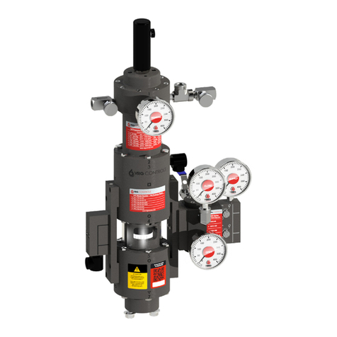
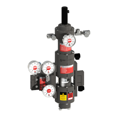
RP Series Regulator Pilots are reversible pressure control regulator devices designed for use in conjunction with pilot-
operated regulators bodies manufactured by others. They can be used for pressure reducing, backpressure or relief type
applications. The RP Series Regulator Pilots are designed for Gas applications and provide a higher performance than
other “standard-issue regulator pilots.
RP Series Regulator Pilots are available with three (3) differently sized sensing diaphragms that are suited for different
applications based upon the maximum sensing pressure applied and the desired setpoint pressure to be achieved. See
Table 3.0 for additional information.
RP Series Regulator Pilots utilize an internal seat & nozzle internal loading configuration as noted by the characters “SN”
in the model number derivation. Internal nozzles are available in 3/32 in dia. and 1/8 in dia. sizes. The internal nozzles
may be interchanged to achieve required performance based upon application criteria. Standard issue internal nozzle is
3/32 in dia which is suitable for typical “pipeline applications.” For “close-coupled” applications such as power plant fuel
gas feed and 2-stage pressure cut, a 1/8 in dia. internal nozzle should be installed. When utilizing a 1/8 in internal nozzle
a “L” Adjustable Orifice is required.
RP Series Regulator Pilots are available with two (2) different sensing chamber configurations. The “CS” closed spring
sensing chamber design features a design that minimizes forces applied to the pilot internal mechanism and exhibits the
optimum control accuracy, sensitivity and stability. Furthermore the “CS” closed spring sensing chamber encapsulates
the control spring within the process media eliminating exposure to the local atmosphere and protecting it from corrosive
environments. The “OS” open spring sensing chamber provides high performance control accuracy at a reduced price
with fewer parts.
RP Series Pilots parts are interchangeable across model numbers and even across some product series in the VRG
products lines. This interchangeability facilitates understanding of maintenance and operation and may benefit operators
in the field in the event that parts may be needed on an immediate basis for conversion of models and/or repair. All RP
Series Pilots feature body construction with VRG Military Grade Aluminum Alloy with “Stealth System” Corrosion Protection
materials and 316 Stainless Steel to ensure durability and long life in even the most corrosive environments.
The RP Series Regulator Pilot features a manifolded integral Adjustable Orifice installed on the INLET side of the device.
Three (3) different sizes of Adjustable Orifices are available (S, M, and L) to adapt to different operating scenarios and
ensure optimal performance. For “close-coupled” applications such as power plant fuel gas feed and 2-stage pressure
cut, a 1/8 in dia. internal nozzle should be installed. When utilizing a 1/8 in internal nozzle a “L” Adjustable Orifice is
required.
RP Pilots are available in two (2) different Actions: Normally Open (NO) & Normally Closed (NC). Normally Open (NO) is
the standard issue product from VRG Controls and is commonly utilized for Pressure Reduction and Monitor
Overpressure applications. Reference the “RP Model Number Identification Label” on the body of the RP Regulator Pilot
to confirm the Action of the pilot. Note that all RP Regulator Pilots may be field-converted from Normally Open (NO) to
Normally Closed (NC) and vice-versa without the need for any additional parts. If an RP unit action is changed, we
recommend that you obtain a new “RP Model Number Identification Label” in order to display the proper action.
Ver 021821
Page 6 of 24
VRG Controls, LLC
1199 Flex Court, Unit B ● Lake Zurich, Illinois 60047 USA
Toll-Free USA & Canada +844-FLOW-VRG ● www.vrgcontrols.com ● email: sales@vrgcontrols.com
RP Series Regulator Pilot
Installation, Operations, Maintenance - IOM
Installation:
ATTENTION:
Personal injury, damage, or explosion due to leakage of accumulated gas, or rupture of pressurized
components could result if this pilot is overpressured or is installed where operating parameters could exceed
the design limits as indicated in this manual, or where parameters exceed the ratings of the regulator body,
adjacent piping or piping components & fittings. Verify the pressure limitations of pilot and the regulator on
which it is installed to ensure neither device is overpressured. To avoid injury or damage to property, incorporate relief
valves or pressure limiting devices to prevent operating parameters from exceeding required limits. Reference U.S. code
of Federal Regulations, by the National Fire Codes of the National Fire Protection Association, or by other applicable
codes or codes mandated by the operating company as needed.
WARNING
Regulator Pilots and Pilot Operated Regulators installed in enclosed or confined spaces should be provided
with adequate ventilation to prevent the potential of gas accumulation from leakage or venting. Leakage and
vent gas can accumulate causing property damage, severe injury or death. Atmospheric vent ports should be
vented to a safe area away from air intakes, or any hazardous location.
PERSONNEL: Installation of RP Series Regulator Pilots and other manufacture’s Pilot Operated Regulator
Bodies should be performed by qualified personnel that are familiar with high pressure natural gas piping and regulator
technologies.
INSPECTION: Inspect the RP Series Pilot for damage that might have occurred in shipping and handling. Do NOT use
any product that has any remote semblance of damage. Care should also be taken to ensure that no damage exists on
previously installed products that may have been installed at previous locations. If the origin or operational capability of
any product is suspect or unknown, we recommend confirmation of fitness for service by a qualified technician or by VRG
Controls.
ACTION: Inspect the RP Model Number Identification Label AND the Body of the RP Series Pilot to ensure that the unit
has the appropriate ACTION for the desired application. Figures XX and Table XX provide necessary information to
confirm RP Series Pilot Action.
INSTALLATION ORIENTATION: RP Series Regulator Pilots may be installed in any orientation. However, for optimum
results and ease of maintenance, it is typically receommended to install RP Series Pilots in a vertical orientation with the
RP Series Setpoint Adjustment Screw pointing upward.
PILOT MOUNTING: The RP Series Pilot may be installed utilizing a convenient mounting bracket available from VRG
Controls. The RP Pilot may be wall mounted or 2.0 in pipe mounted.
PIPING: Appropriate pipe thread seal tape should be applied to all fittings installed on the RP Pilot. Use of pipe dope is
also encouraged to minimize potential for galling or damage to threaded connections. All threaded connection on the RP
Pilot are ¼ in FNPT.
PILOT SUPPLY LINES: 3/8in stainless steel tubing or ¼ in diameter threaded, non-restricted connections should be
utilized to make connections to the RP Series Pilot. The INLET connection should be made with restrictions in the piping
components. In the event that an isolation valve is installed in the INLET connection, it should be a full-opening type
without restriction.
FILTRATION: Most gas pipeline applications do not require a filter on the INLET connection. If the application may
exhibit dirty gas, an appropriate filter should be applied upstream of the INLET connection to prevent clogging of the
ADJUSTABLE ORIFICE. The filter should be application appropriate with adequate capacity with filtration to 10μ.
PILOT DISCHARGE (OUT): 3/8in stainless steel tubing or ¼ in diameter threaded, non-restricted connections should be
utilized to make connections to the RP Series Pilot. The OUT connection should be made with restrictions in the piping
components. In the event that an isolation valve is installed in the OUT connection, it should be a full-opening type
without restriction.
PILOT GAS PRE-HEATERS: Pilot INLET gas may be heated to prevent excessive refrigeration effects and potential
formation of ice or hydrates in the system. Pilot INLET gas heaters should be connected after the pilot filter upstream of
Ver 021821
Page 7 of 24
VRG Controls, LLC
1199 Flex Court, Unit B ● Lake Zurich, Illinois 60047 USA
Toll-Free USA & Canada +844-FLOW-VRG ● www.vrgcontrols.com ● email: sales@vrgcontrols.com
RP Series Regulator Pilot
Installation, Operations, Maintenance - IOM
the INLET port. Note that Pilot pre-heaters are NOT REQUIRED and may be considered per application when large
pressure drops result in severe refrigeration effects.
SENSING LINES: Sensing Lines should be run from the Sensing Port of the RP Series Regulator Pilot to a point roughly
10 pipe diameters from the outlet of the pilot-operated regulator body. See table below for recommended piping
configurations for Sensing Lines. Reduce as necessary to connect to the ¼ in FNPT ports on the RP Series Regulator
Pilot. The Sensing Line connection should be avoid turbulent areas (valves, reducers, and elbows) and should have a full
bore opening to the pipe. Isolation valves are typically recommended on the Sensing Line(s) and should be non-restricted,
full opening type.
Table 1.0 –Recommended Sensing Line Configuration for RP Series Pilots
Desired Setpoint Pressure
in. WC ≤ SETPOINT < 2.0 psig
2.0 psig ≤ SETPOINT < 5.0 psig
5.0 psig ≤ SETPOINT
½ in Pipe (Min.)
½ in Seamless SS Tubing
3/8in Seamless SS Tubing
Maintenance
Regulator and control device parts utilized in gas regulation applications are subject to normal wear and should be
inspected and replaced as necessary. The frequency of inspection and replacement of parts depends on severity of
service conditions and/or the requirements of local, state, federal regulations. You should consult your company
standards and regulations to determine protocol for maintenance on your equipment. It is critical to ensure that the RP
Model Number Identification Labels, RP Spring Control Range Labels, and other applicable labels are updated and
maintained to ensure legibility and accurately reflect the operation limitations of the device.
WARNING
Before removal, disassembly, or initiating maintenance ensure that the RP Series Regulator Pilot and the Pilot-
Operated Regulator on which it is installed have been isolated from the process. All pressurized gas must be
safely vented from the RP and Regulator System. Failure to relieve all pressure from the system may result in
property damage, severe injury or death.
Applications:
The RP Series Regulator Pilot is designed to provide self-contained pressure control when incorporated with pilot-
operated regulators. The system utilizes pressurized natural gas or from the pipeline to operate and can address a
number of common pipeline pressure control applications. Contact VRG Controls for assistance with your application.
•Primary Pressure Control (Active)
•Overpressure Protection (Monitor)
•Overpressure Protection (Relief)
•Underpressure Protection (Standby)
•Backpressure Control
•Two-Stage Pressure Control
•Power Plant Fuel Gas Feed
Ver 021821
Page 8 of 24
VRG Controls, LLC
1199 Flex Court, Unit B ● Lake Zurich, Illinois 60047 USA
Toll-Free USA & Canada +844-FLOW-VRG ● www.vrgcontrols.com ● email: sales@vrgcontrols.com
RP Series Regulator Pilot
Installation, Operations, Maintenance - IOM
Table 2.0 –RP Series Regulator Pilot Technical Specifications
RP Series
RP-SN-CS
RP-SN-OS
Type
Regulator Pilot
Regulator Pilot
Internal Valve Logic
Seat & Nozzle
Seat & Nozzle
Spring Chamber Type
Closed Spring (CS)
Open Spring (OS)
Outputs
Single, Variable
Single, Variable
Available Action
Normally Open (NO)1
Normally Closed (NC)1
Normally Open (NO)1
Normally Closed (NC)1
Setpoint Range
1.25 - 1500 psig
(9.0 - 10,342 kPa)
9 - 700 psig
(62 –4,826 kPa)
Temperature Range
-20°F to +160°F (-29°C to +71°C)
Pneumatic
Supply Gas Quality
Dry, Filtered @ 10µ Natural Gas
Max Inlet Pressure
1500 psig
(10,342 kPa)
1500 psig
(10,342 kPa)
Max Differential Pressure
700 psid (4,826 kPad) –“225”
700 psid (4,826 kPad) –“700”
1500 psid (10,342 kPad) –“1500”
700 psid (4,826 kPad) –“700”
Connections
All Ports ¼ FNPT
Construction
External Parts
VRG Military Grade Aluminum Alloy with “Stealth System” Corrosion Protection
304 SS –Optional Construction
Internal Parts
All Internal Parts 316 SS
Diaphragms
High Performance Nylon Reinforced Buna-N, VITON (Optional)
O-Rings
Buna-N, VITON (Optional)
Control Springs
Painted Alloy Steel
Gauges
2.5 in. Liquid-Filled SS Case & Body (Optional)
Weight (Approx.)
11 lbs.
(5.0 kg)
10 lbs.
(4.5 kg)
Dimensions (Approx.)
12 in X 7.5 in X 4.0 in
(305 mm X 191 mm X 102 mm)
13.5 in X 7.5 in X 4.0 in
(343 mm X 191 mm X 102 mm)
Application Guide
Pressure Reducing/Monitor
Optimum (NO)
Very Good (NO)
Relief/Backpressure
Optimum (NC)
Very Good (NC)
Boiler Power Plant
Optimum
--
Asphalt Plants
Optimum
--
Duct Burner Control
Optimum
--
Liquid Pressure Control
Optimum
Very Good
Performance Guide
Sulfur Formation Problems
Sulfur Resistant
Sulfur Resistant
Flow Capacity
High Capacity
High Capacity
Control Accuracy
Ultimate Accuracy
Very Good Accuracy
Control Stability
Ultimate Stability
Very Good Stability
Droop Performance
Low Droop
Low Droop
Notes:
1. Normally Open (NO) and Normally Closed (NC) may be converted without additional parts.
Ver 021821
Page 9 of 24
VRG Controls, LLC
1199 Flex Court, Unit B ● Lake Zurich, Illinois 60047 USA
Toll-Free USA & Canada +844-FLOW-VRG ● www.vrgcontrols.com ● email: sales@vrgcontrols.com
RP Series Regulator Pilot
Installation, Operations, Maintenance - IOM
Table 2.0 - Model Number Explanation:
Base Model
Pressure Series
Internal Valve Logic
Spring Chamber Type
RP
Pilot Regulator
225
225 psig Max Sensing
SN
Seat & Nozzle
OS
Open Spring Chamber
700
700 psig Max Sensing
CS
Closed Spring Chamber
1500
1500 psig Max Sensing
Example: Model RP-700-SN-CS
Regulator Pilot, 700 psig Max Sensing, Seat & nozzle Internal Valve, Close Spring Chamber Design
RP Model Number Identification Label:
RP Spring Control Range Label:
Ver 021821
Page 10 of 24
VRG Controls, LLC
1199 Flex Court, Unit B ● Lake Zurich, Illinois 60047 USA
Toll-Free USA & Canada +844-FLOW-VRG ● www.vrgcontrols.com ● email: sales@vrgcontrols.com
RP Series Regulator Pilot
Installation, Operations, Maintenance - IOM
Table 3.0 –RP Series Available Control Spring Configurations
RP Model
Control
Range
Spring
Color
Setpoint
Change / Rev.
Control
Spring
Models:
RP-225-SN-CS2
3.0 - 14 psig
(20.6 - 97 kPa)
Black
0.8 psig
(5.5 kPa)
CS-0100
5 - 53 psig
(55 - 365 kPa)
Brown
3.1 psig
(21.4 kPa)
CS-0110
16 - 100 psig
(110 - 689 kPa)
Grey
8 psig
(55 kPa)
CS-0120
40 - 170 psig
(276 - 1172 kPa)
Orange
20.2 psig
(139 kPa)
CS-0130
65 - 205 psig
(448 - 1413 kPa)
White
32.2 psig
(222 kPa)
CS-0135
100 - 225 psig
(689 - 1551 kPa)
Purple
44.2 psig
(305 kPa)
CS-0140
Models:
RP-700-SN-CS2
RP-700-SN-OS1
9 - 45 psig
(62 - 310 kPa)
Black
2.4 psig
(17 kPa)
CS-0100
30 - 160 psig
(241 - 1103 kPa)
Brown
9.6 psig
(73 kPa)
CS-0110
75 - 310 psig
(517 - 2137 kPa)
Grey
24.5 psig
(175 kPa)
CS-0120
150 - 520 psig
(1034 - 3585 kPa)
Orange
62.1 psig
(423 kPa)
CS-0130
240 - 635 psig
(1655 - 4378 kPa)
White
98.9 psig
(687 kPa)
CS-0135
350 - 700 psig
(2413 - 4826 kPa)
Purple
135.9 psig
(926 kPa)
CS-0140
Models:
RP-1500-SN-CS2
30 - 90 psig
(207 - 620 kPa
Black
5.0 psig
(34 kPa)
CS-0100
50 - 335 psig
(345 - 2309 kPa)
Brown
19.7 psig
(149 kPa)
CS-0110
100 - 640 psig
(689 - 4412 kPa)
Grey
50.4 psig
(361 kPa)
CS-0120
265 - 1070 psig
(1827 - 7377 kPa)
Orange
127.6 psig
(870 kPa)
CS-0130
400 - 1300 psig
(2758 –8962 kPa)
White
203.2 psig
(870 kPa)
CS-0135
625 - 1500 psig
(4309 –10341 kPa)
Purple
279.3 psig
(1904 kPa)
CS-0140
Notes:
1. “Open Spring” spring cartridge available for economical standard applications
2. “Closed Spring” spring cartridge available for high performance applications.
Ver 021821
Page 11 of 24
VRG Controls, LLC
1199 Flex Court, Unit B ● Lake Zurich, Illinois 60047 USA
Toll-Free USA & Canada +844-FLOW-VRG ● www.vrgcontrols.com ● email: sales@vrgcontrols.com
RP Series Regulator Pilot
Installation, Operations, Maintenance - IOM
Flow Calculations
Critical Flow Equation:
󰇛󰇜
󰇛󰇜
Where:
Variable
Description
Unit
Qc
Critical Flow Across Inlet Orifice
Scfh
P1
Supply Pressure
Psig
Cv
Flow Factor
--
G
Specific Gravity of Gas
--
T
Gas Temperature
°F
Flow Coefficient Tables (Cv)
Table 4.0 –Adjustable Orifice Flow Coefficients
Adjustable Orifice Setting
Installed Orifice
0
1
2
3
4
5
6
7
Standard
0.006
0.009
0.018
0.044
0.069
0.096
0.111
0.126
Medium (M)
0.042
0.045
0.062
0.089
.134
0.172
0.211
0.249
Large (L)
0.042
0.063
0.172
0.328
0.461
0.578
0.634
0.675
Page 12 of 24
VRG Controls, LLC
1199 Flex Court, Unit B ● Lake Zurich, Illinois 60047 USA
Toll-Free USA & Canada +844-FLOW-VRG ● www.vrgcontrols.com ● email: sales@vrgcontrols.com
RP Series Regulator Pilot
Installation, Operations, Maintenance - IOM
Table 5.0 RP Series Regulator Pilot Assembly Configuration Summary
Component
RP-225-SN-CS
RP-225-SN-CS
RP-700-SN-CS
RP-700-SN-CS
RP-700-SN-OS
RP-700-SN-OS
RP-1500-SN-CS
RP-1500-SN-CS
Output
Normally
Open
Normally
Closed
Normally
Open
Normally
Closed
Normally
Open
Normally
Closed
Normally
Open
Normally
Closed
Sensing
Cartridge Type
Closed
Spring
Closed
Spring
Closed
Spring
Closed
Spring
Open
Spring
Open
Spring
Closed
Spring
Closed
Spring
Internal Valve
Logic
SN
SN
SN
SN
SN
SN
SN
SN
Cartridge Top
Flange
1
1
1
1
1
1
1
1
Spring Cartridge
2
2
2
2
2
2
2
2
Sensing Adapter
3
3
3
3
3
3
3A
3A
Sensing Spacer
3A
3A
--
--
--
--
3B
3B
Block Spacer
--
--
--
--
--
--
▼
▼
Pilot Block
(TOP)
▲
●
▲
●
●
▲
▲
●
Pilot Block
(BOTTOM)
●
■
●
■
■
●
●
■
Block Spacer
--
--
--
--
--
--
▲
▲
Pilot Bottom
Flange
7
7
7
7
7
7
7
7
Left Hand
Manifold
ORIFICE
BLOCK
ORIFICE
BLOCK
ORIFICE
BLOCK
ORIFICE
BLOCK
ORIFICE
BLOCK
ORIFICE
BLOCK
ORIFICE
BLOCK
ORIFICE
BLOCK
Right Hand
Manifold
NPT
OUTPUT
NPT
OUTPUT
NPT
OUTPUT
NPT
OUTPUT
NPT
OUTPUT
NPT
OUTPUT
NPT
OUTPUT
NPT
OUTPUT
Notes:
1. Normally Open configuration utilized for PRESSURE REDUCING application and is most common configuration.
2. Normally Open configuration utilized for BACKPRESSURE and RELIEF VALVE applications.
Page 13 of 24
VRG Controls, LLC
1199 Flex Court, Unit B ● Lake Zurich, Illinois 60047 USA
Toll-Free USA & Canada +844-FLOW-VRG ● www.vrgcontrols.com ● email: sales@vrgcontrols.com
RP Series Regulator Pilot
Installation, Operations, Maintenance - IOM
Table 6.0 –RP Series Regulator Pilot Available Models
RP-225-SN-CS (Normally Open)
PA-0190
RP-225-SN-CS (Normally Closed)
PA-0191
Page 14 of 24
VRG Controls, LLC
1199 Flex Court, Unit B ● Lake Zurich, Illinois 60047 USA
Toll-Free USA & Canada +844-FLOW-VRG ● www.vrgcontrols.com ● email: sales@vrgcontrols.com
RP Series Regulator Pilot
Installation, Operations, Maintenance - IOM
Table 6.0 –RP Series Regulator Pilot Available Models (Cont’d.)
RP-700-SN-CS (Normally Open)
PA-0200
RP-700-SN-CS (Normally Closed)
PA-0201
Page 15 of 24
VRG Controls, LLC
1199 Flex Court, Unit B ● Lake Zurich, Illinois 60047 USA
Toll-Free USA & Canada +844-FLOW-VRG ● www.vrgcontrols.com ● email: sales@vrgcontrols.com
RP Series Regulator Pilot
Installation, Operations, Maintenance - IOM
Table 6.0 –RP Series Regulator Pilot Available Models (Cont’d.)
RP-700-SN-OS (Normally Open)
PA-0300
RP-700-SN-OS (Normally Closed)
PA-0301
Page 16 of 24
VRG Controls, LLC
1199 Flex Court, Unit B ● Lake Zurich, Illinois 60047 USA
Toll-Free USA & Canada +844-FLOW-VRG ● www.vrgcontrols.com ● email: sales@vrgcontrols.com
RP Series Regulator Pilot
Installation, Operations, Maintenance - IOM
Table 6.0 –RP Series Regulator Pilot Available Models (Cont’d.)
RP-1500-SN-CS (Normally Open)
PA-0210
RP-1500-SN-CS (Normally Closed)
PA-0215
Page 17 of 24
VRG Controls, LLC
1199 Flex Court, Unit B ● Lake Zurich, Illinois 60047 USA
Toll-Free USA & Canada +844-FLOW-VRG ● www.vrgcontrols.com ● email: sales@vrgcontrols.com
RP Series Regulator Pilot
Installation, Operations, Maintenance - IOM
Page 18 of 24
VRG Controls, LLC
1199 Flex Court, Unit B ● Lake Zurich, Illinois 60047 USA
Toll-Free USA & Canada +844-FLOW-VRG ● www.vrgcontrols.com ● email: sales@vrgcontrols.com
RP Series Regulator Pilot
Installation, Operations, Maintenance - IOM
Table 8.0 –Factory Quality Checklist RP Series Regulator Pilot
Date:
VRG Invoice Number:
Personnel:
Model Number:
Serial Number:
Customer:
Customer Tag:
Supply Pressure
Discharge Pressure
Orifice Setting
_______
Procedure
Verified
Notes
Apply Maximum Sensing Pressure 30 min.
□ VERIFY
Adjust RP to Setpoint
□ VERIFY
Friction Test
□ VERIFY
Gage Check (if applicable)
□ VERIFY
Valve Leak Check
□ VERIFY
Assembly Leak Check
□ VERIFY
Seat Check
□ VERIFY
Sensitivity Check
□ VERIFY
Label Check
□ VERIFY
Notes:
Page 19 of 24
VRG Controls, LLC
1199 Flex Court, Unit B ● Lake Zurich, Illinois 60047 USA
Toll-Free USA & Canada +844-FLOW-VRG ● www.vrgcontrols.com ● email: sales@vrgcontrols.com
RP Series Regulator Pilot
Installation, Operations, Maintenance - IOM
Table 9.0 - RP-SN Series Regulator Pilots Application Schematics - Table of Contents
No.
RP Series
Action
Notes
Application
Page
1
RP-SN-CS Series
Normally Open
Closed Spring Chamber
Pressure Reducing
20
1
RP-SN-OS Series
Normally Open
Open Spring Chamber
Pressure Reducing
20
2
RP-SN-CS Series
Normally Closed
Closed Spring Chamber
Backpressure
21
3
RP-SN-CS Series
Normally Closed
Closed Spring Chamber
Relief Valve
21
4
RP-SN-CS Series
Normally Open
Closed Spring Chamber
ESC Electronic Setpoint
Control
Pressure Reducing
22
Notes:
1. Contact VRG Controls for additional schematics that do not appear in this manual.
Page 20 of 24
VRG Controls, LLC
1199 Flex Court, Unit B ● Lake Zurich, Illinois 60047 USA
Toll-Free USA & Canada +844-FLOW-VRG ● www.vrgcontrols.com ● email: sales@vrgcontrols.com
RP Series Regulator Pilot
Installation, Operations, Maintenance - IOM

This manual suits for next models

4

Other VRG Controls Controllers manuals

VRG Controls VPC BV Series User manual

VRG Controls

VRG Controls VPC BV Series User manual

VRG Controls VPC SN Series User manual

VRG Controls

VRG Controls VPC SN Series User manual

VRG Controls RCVC 3000 User manual

VRG Controls

VRG Controls RCVC 3000 User manual

Popular Controllers manuals by other brands

Alcor AU9381 Technical reference manual

Alcor

Alcor AU9381 Technical reference manual

Pfannenberg DTT 6801 Series Original operating manual

Pfannenberg

Pfannenberg DTT 6801 Series Original operating manual

Infineon Technologies XC161 user manual

Infineon Technologies

Infineon Technologies XC161 user manual

Solid State Logic Nucleus2 user guide

Solid State Logic

Solid State Logic Nucleus2 user guide

Samson 43-2 Mounting and operating instructions

Samson

Samson 43-2 Mounting and operating instructions

Danfoss 140F1139 Installation and user guide

Danfoss

Danfoss 140F1139 Installation and user guide

Clic Cardinal WD-02.2 installation manual

Clic

Clic Cardinal WD-02.2 installation manual

Midea KJR-12B/DP(T) owner's manual

Midea

Midea KJR-12B/DP(T) owner's manual

CenterLine VeriFast MicroView 1.0 user manual

CenterLine

CenterLine VeriFast MicroView 1.0 user manual

Hunter Genesis Programming and operations manual

Hunter

Hunter Genesis Programming and operations manual

Brightlink BL-VW22 operating instructions

Brightlink

Brightlink BL-VW22 operating instructions

IFM Electronic Ecomat 300 Supplementary manual

IFM Electronic

IFM Electronic Ecomat 300 Supplementary manual

Hobo MicroRX quick start

Hobo

Hobo MicroRX quick start

Trane Symbio 800 installation instructions

Trane

Trane Symbio 800 installation instructions

Groschopp RBD-325-4/6-S product manual

Groschopp

Groschopp RBD-325-4/6-S product manual

Siemens Desigo PXC4.E16 manual

Siemens

Siemens Desigo PXC4.E16 manual

Crest Audio N-CODER Specifications

Crest Audio

Crest Audio N-CODER Specifications

Ulvac UK-2 instruction manual

Ulvac

Ulvac UK-2 instruction manual

manuals.online logo
manuals.online logoBrands
  • About & Mission
  • Contact us
  • Privacy Policy
  • Terms and Conditions

Copyright 2025 Manuals.Online. All Rights Reserved.