VSpeak ECU Converter User manual

ECU converter JetCat Version: 1.0 www.VSpeak-modell.de Page 1/38
ECU converter JetCat
Manual Version 1.0
Introduction
The VSpeak ECU Converter provides the data of the JetCat ECU on the telemetry system of
your remote control system.
In the systems Jeti Duplex and Graupner HoTT the VSpeak ECU converter replaces the JetCat
GSU (Ground Support Unit) completely, that means not only the indicators of the GSU are
displayed on the transmitter - also most entries can be made conveniently via the transmitter.
To avoid unwanted electrical effects between the ECU and RC-system the VSpeak ECU
Converter is galvanically isolated.
The VSpeak ECU Converter can be software-updated by the user
Supported are:
60 mm
17 mm
17 mm

ECU converter JetCat Version: 1.0 www.VSpeak-modell.de Page 2/38
Content Page
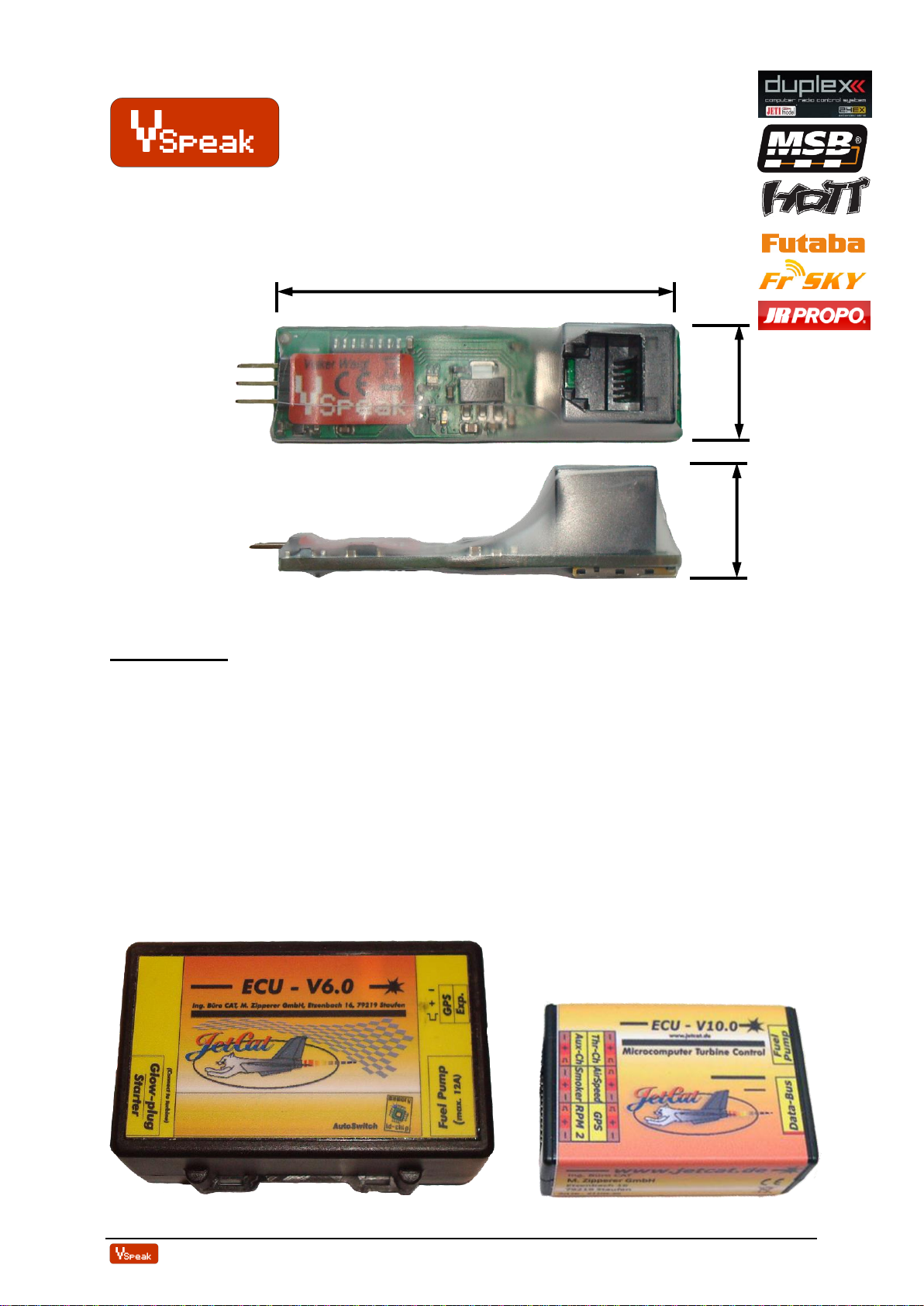
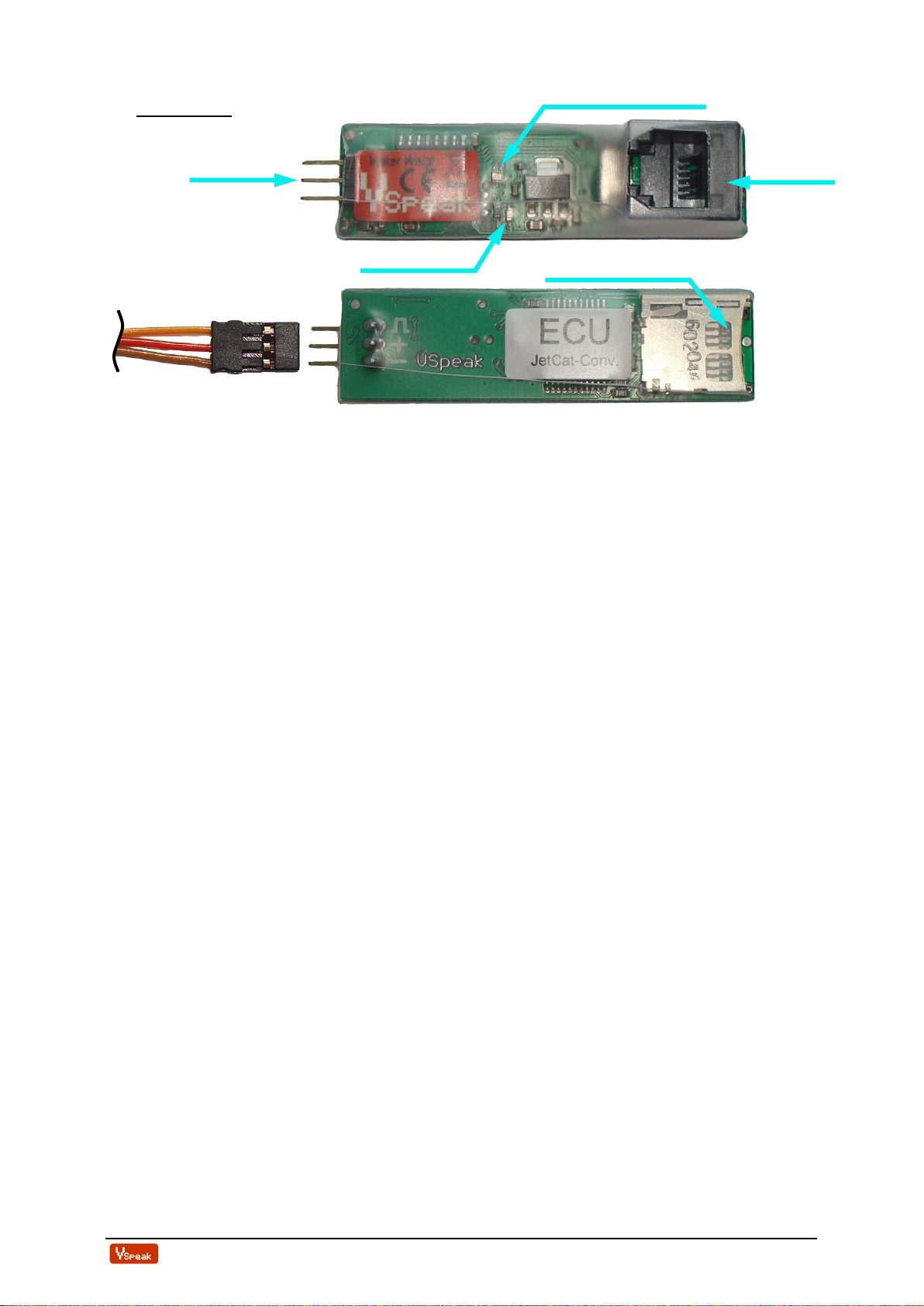
1Hardware................................................................................................................................ 4
1.1 Connection Telemetry port................................................................................................... 4
1.2 Connection Data port ............................................................................................................ 4
2Telemetry................................................................................................................................ 5
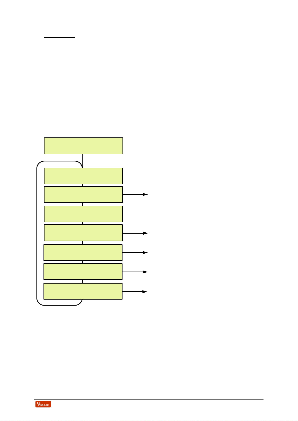
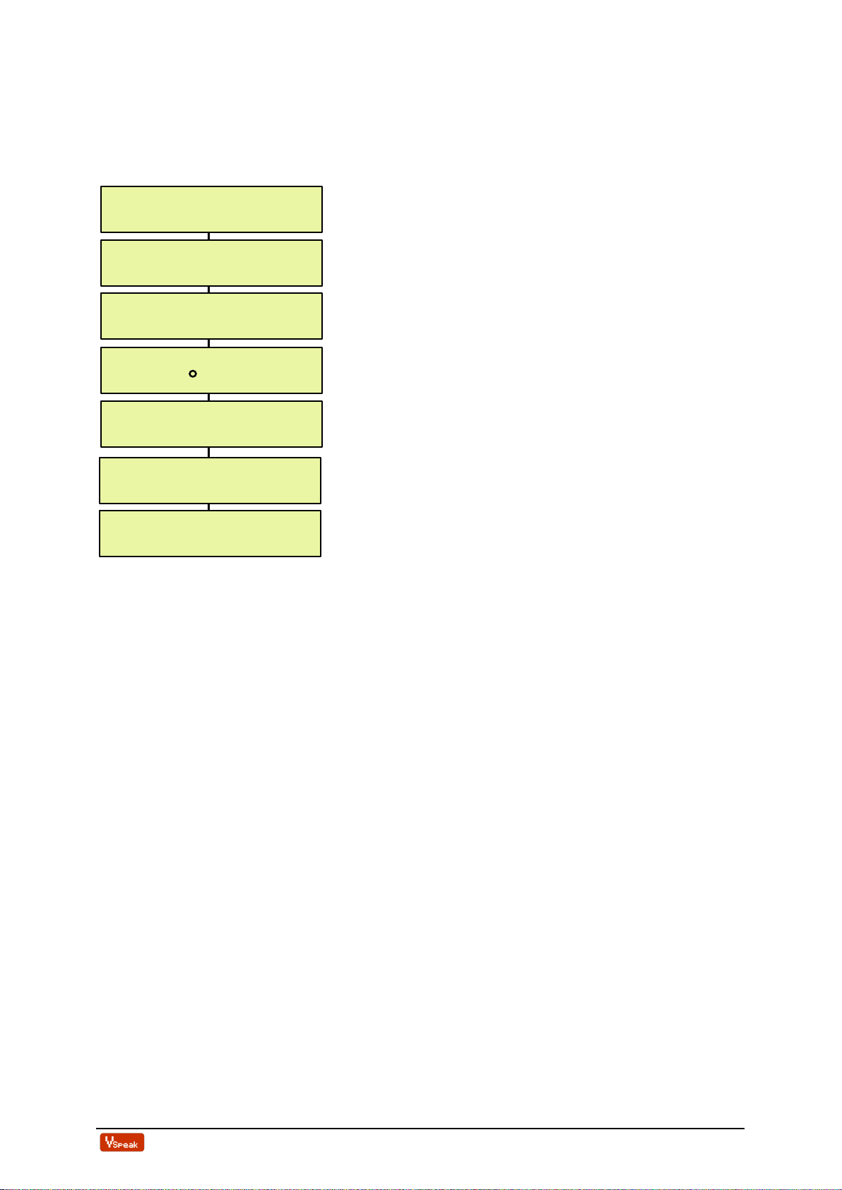
2.0 Select Telemetry System / Global Parameters .................................................................... 5
2.1 Jeti Duplex EX ....................................................................................................................... 7
2.1.1 EX-data DC/DS-radio...............................................................................................................7
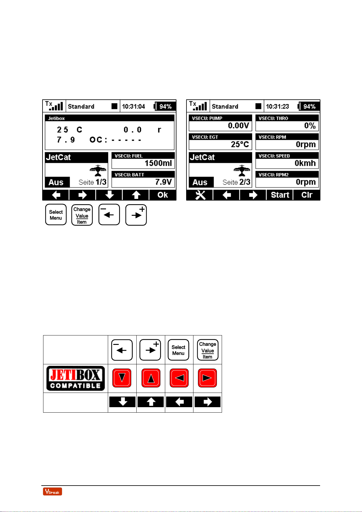
2.1.2 Jetibox.......................................................................................................................................7
2.1.2.1 Key assignment ...................................................................................................................................... 7
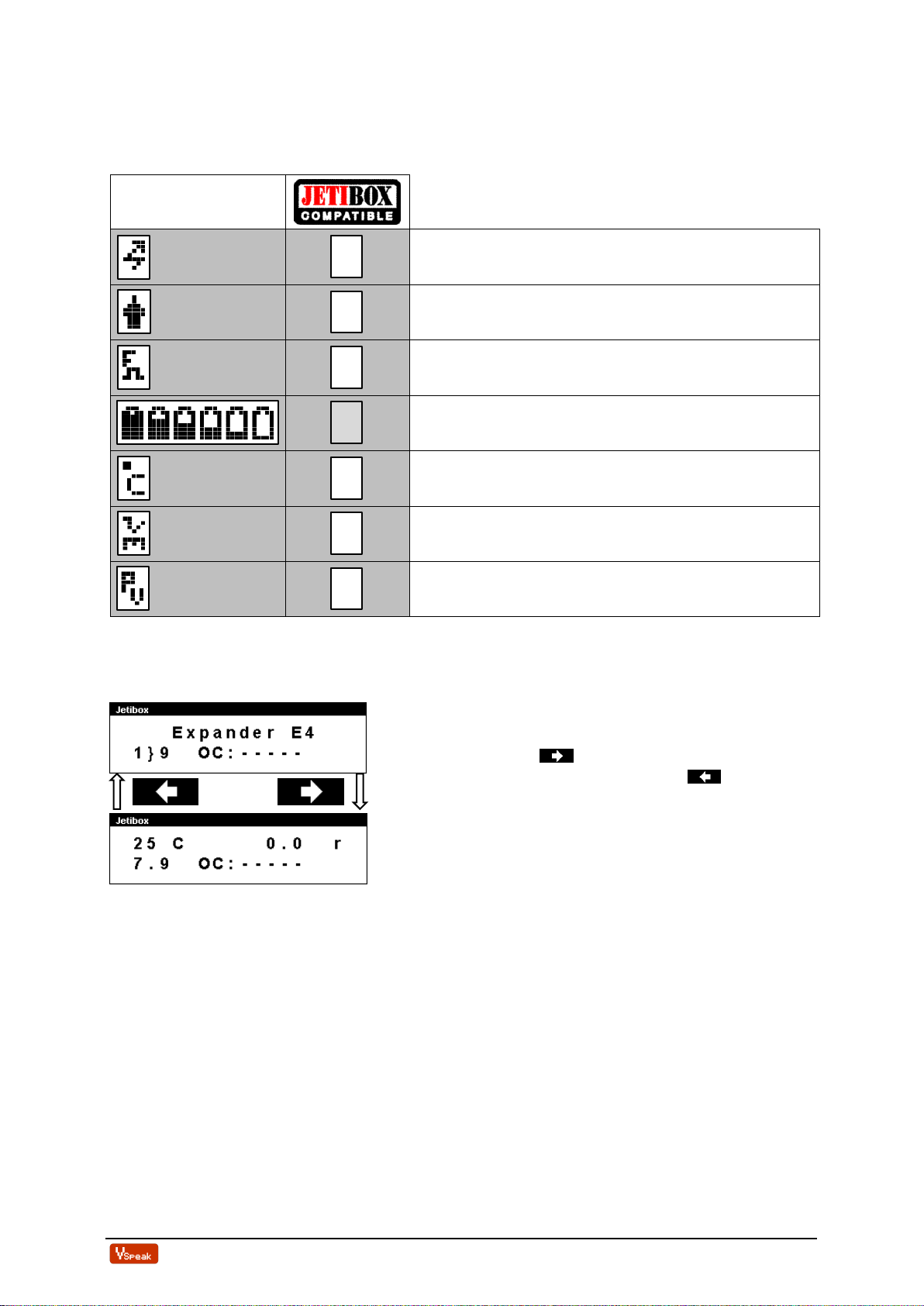
2.1.2.2 Special Characters................................................................................................................................. 8
2.1.2.3 Expandermenu ....................................................................................................................................... 8
2.1.2.4 Turbinestatus / OFF-Condition –numerial Values................................................................................ 9
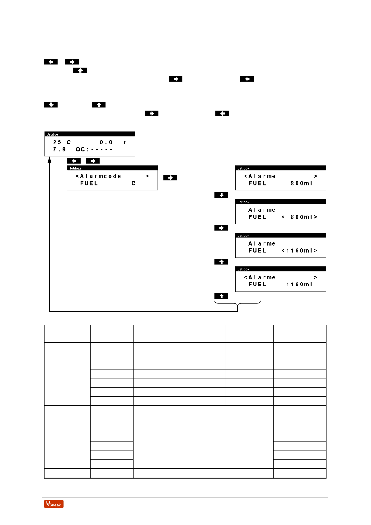
2.1.2.5 Alarms / Parameterization ................................................................................................................... 10
2.1.3 Profibox - autonomous telemetry system for JetCat-ECU......................................................12
2.2 Multiplex MLink (MSB)...................................................................................................... 13
2.2.1 Address-Assignment................................................................................................................13
2.2.2 Turbinestatus / OFF-Condition ..............................................................................................13
2.2.3 Setup........................................................................................................................................14
2.3 Graupner HoTT................................................................................................................... 15
2.3.1 Sensortype...............................................................................................................................15
2.3.2 Textdisplay..............................................................................................................................15
2.3.2.1 Special Characters............................................................................................................................... 16
2.3.2.2 Key assignment .................................................................................................................................... 16
2.3.3 Data-Display/Speech ..............................................................................................................17
2.3.3.1 GAM - General Air Modul................................................................................................................... 17
2.3.3.2 ESC - Electronic Speed Control........................................................................................................... 17
2.3.3.3 VAR –Variometer................................................................................................................................ 18
2.3.4 Alarms / Parameterization......................................................................................................19
2.4 Futaba S.BUS2..................................................................................................................... 21
2.4.1 Registration at the transmitter................................................................................................21
2.4.2 Mapping Sensor –ECU Values ..............................................................................................21
2.4.1 Turbinestatus –numerical "Current"-Values.........................................................................23
2.4.2 Telemetry Box .........................................................................................................................23
2.4.3 Setup........................................................................................................................................24
2.4.4 Alarms.....................................................................................................................................25
2.5 Futaba S.BUS2 V10............................................................................................................. 26
2.5.1 Registration at the transmitter................................................................................................26
2.5.2 Turbinestatus –numerical "Current"-Values.........................................................................27
2.5.3 Setup........................................................................................................................................28
2.5.4 Alarms.....................................................................................................................................28
2.6 FrSKY S.Port ....................................................................................................................... 30
2.6.1 Turbinestatus / OFF-Condition –numerial „Temperature“-Values......................................31
2.6.2 S.Port ID.................................................................................................................................32
2.6.3 Setup........................................................................................................................................32
2.6.4 LUA script for Taranis............................................................................................................33
2.7 JR PROPO............................................................................................................................ 34
2.7.1 Turbinestatus –numerical "Current"-Values.........................................................................35
2.7.2 Setup........................................................................................................................................36
3Update................................................................................................................................... 37
4Accessories............................................................................................................................ 37

ECU converter JetCat Version: 1.0 www.VSpeak-modell.de Page 3/38
4.1 Telemetry patch cable.......................................................................................................... 37
4.2 Data patch cable................................................................................................................... 37
4.3 Programming adapter......................................................................................................... 37
4.4 Micro SD card...................................................................................................................... 37
4.5 Western cable connector ..................................................................................................... 37
4.6 Y Western cable connector ................................................................................................. 37
5Instructions for disposal...................................................................................................... 37
6Technical data ...................................................................................................................... 38
7EG Declaration of Conformity ........................................................................................... 38
8Version history..................................................................................................................... 38
9Contact.................................................................................................................................. 38

ECU converter JetCat Version: 1.0 www.VSpeak-modell.de Page 4/38
1Hardware
Data LED: green(ON) →Receiving data from JetCat ECU
green(flashing) →Receiving data from JetCat ECU and data transfer to receiver
(Jeti only then, if JetiBox buttons are activated)
red (ON) →Data exchange with JetCat GSU (via Programming adapter)
The blue LED is blinking every second to signal the normal function of the ECU Converter.
The Micro SD card slot is used for updates.
The attachment of the VSpeak ECU converter in the model can be done with velcro tape, double
sided tape or cable ties.
1.1 Connection Telemetry port
With the servo patch cable included in the delivery, the Telemetry port of the VSpeak ECU
converter is connected to the telemetry input of the respective receiver.
1.2 Connection Data port
With the Western patch cable included in the delivery, the Data port of the VSpeak ECU
converter is connected with the JetCat ECU or I/O board. The VSpeak ECU Converter can be
connected wherever the JetCat GSU is connected. With the help of a Y-connector
(eg from reichelt.de, see chapter 4), a "parallel operation" of JetCat GSU and VSpeak converter
is also possible.
Micro SD card slot
Data LED green/red
Data Port
blue LED
Telemetry-
port

ECU converter JetCat Version: 1.0 www.VSpeak-modell.de Page 5/38
2Telemetry
The voltage for the VSpeak ECU Converter is supplied by the JetCat ECU. As soon as you
switch on the JetCat ECU and apply a valid signal to the throttle channel (either from the radio
or a servo tester) you will get telemetry data. Otherwise no data is generated
2.0 Select Telemetry System / Global Parameters
The telemetry system can be adjusted by using the Programming adapter (s. section
Accessories) and the JetCat GSU.
If ECU converter, GSU, receiver- or turbine battery are plugged into the programming adapter,
the version of the ECU converter appears after a short initialization, followed by the display of
the currently set remote control system.
The navigation takes place in the usual way, ie "scroll" between the parameters with the
+/- buttons - Value change with the pushed "Change Value / Item" button and added +/-
buttons, then instead of the ":" a small arrow shows the changed values.
With Jeti and HoTT, all other settings can be made directly from the transmitter. For all other
remote control systems further specific settings can be made (follow the respective section).
With the "Limits" button you can switch to the "Global" parameters (see next page). Press the
button "Select Menu" returns to the "Telemetry System Selection".
When the "Info" button is pressed, the version of the ECU converter appears.
All other keys of the GSU ("Min / Max" "Run" "Manual" "Set" "Spool") have no function for
the VSpeak ECU converter.
section 2.2.3
section 2.4.5
Te l emetry System
: Futaba
Te l emetry System
: Jet i Dup l ex EX
Te l emetry System
: Mu l t i p l ex MSB
Te l emetry System
: Graupner Hott
section 2.5.4
Te l emetry System
: Futaba V10
section 2.6.3
Te l emetry System
: FrSKY
section 2.7.2
Te l emetry System
: JR PROPO
VSpeak V1 . 0
ECU-Converter

ECU converter JetCat Version: 1.0 www.VSpeak-modell.de Page 6/38
Globale Parameters
If ECU converter, GSU and a (2-3 cell LiPo / LiFe) battery are connected to the Programming
adapter, the "Limits" button is used to set global parameters which are the same for all remote
control systems:
OFF, 10 . . . 2500 ml Set: 800 ml
5.0 . . . 12.0 V Set: 5.0 V
OFF, 20.000 . . . 99.900 rpm Set: OFF
100 . . . 990°C Set: 800°C
OFF, 1.000 . . . 99.900 rpm Set: OFF
OFF, 10 . . . 150 kmh Set: OFF
OFF, 80 . . . 990 kmh Set: OFF
The parameters are largely self-explanatory, lower values as "Low" thresholds and exceeding
of the "High" thresholds trigger alarms, with "OFF" the respective alarm is deactivated.
The "Low ..." alarms are activated after at first exceeding the "Low ..." alarm threshold. The
low RPM (and RPM2) alarm ends at PUMP = 0.00V, which means that the speed alarm is
suitable for signaling a "turbine flameout".
"Set" are the values set at delivery.
Low Battery
: 5 . 0 V
Low RPM
: OFF rpm
Low RPM 2Shaft
: OFF rpm
H i gh EGT
: 800 C
Low A i rspeed
: OFF kmh
H i gh A i rspeed
: OFF kmh
Low Fue l
: 800 m l

ECU converter JetCat Version: 1.0 www.VSpeak-modell.de Page 7/38
2.1 Jeti Duplex EX
2.1.1 EX-data DC/DS-radio
The EX-Protocol is partially backwards compatible. On older non-EX devices you get only
Jetibox functions. On EX devices like the DC/DS radios and the Jeti "Profibox" you get
additional data.
(VSECU … VSpeak ECU Converter):
Press the "left" key (= "Select Menu") and additional pressing the "right" (= "Change Value /
Item") will take you to the settings of the ECU converter (see section 2.1.2.5).
2.1.2 Jetibox
On the Jetibox all data of the JetCat ECU normally displayed on the JetCat GSU are shown
(except characters that cannot be displayed on Jeti Systems).
Furthermore you can use the Jeti-keys to edit most values available on the JetCat GSU. Please
refer to the JetCat manual.
2.1.2.1 Key assignment
JetCat
GSU
DC / DS

ECU converter JetCat Version: 1.0 www.VSpeak-modell.de Page 8/38
2.1.2.2 Special Characters
The JetCat GSU supports some special characters which cannot be displayed on Jeti-systems.
Please refer to the following table how these characters are "translated":
JetCat GSU
Turbine is controlled by the GSU
Glow plug defective
Fail Safe
Battery, charging indicator
Unit "°C"
Unit "rpm"
Pump voltage in "V"
2.1.2.3 Expandermenu If the VSpeak ECU Converter is connected to an
Expander or Centralbox and the ECU Converter display
is activated with the Right button, the only way back
to the expander menu is pressing the Left button
(more then 3 sec).
M
G
F
C
r
P

ECU converter JetCat Version: 1.0 www.VSpeak-modell.de Page 9/38
2.1.2.4 Turbinestatus / OFF-Condition –numerial Values
The turbines status messages are also displayed numerical values. The assignment is given in
the following table.
These status values can be used in Jeti radios, e.g. in logical links, or in LUA-supported radios
for LUA scripts.
Status/OC
Description
0
OFF
1
Slow Down
2
AutoOff
3
WAIT for RPM (Stby/Start)
4
PreHeat1 (only for direct Kerosene startup mode)
5
PreHeat2 (only for direct Kerosene startup mode)
6
Ignite
7
Accleleration delay
8
MainFStrt (only for direct Kerosene startup mode)
9
Keros.FullOn (only for direct Kerosene startup mode)
10
Accelerate
11
Stabilise
12
Learn LO
13
Run (reg.)
14
SpeedReg (Speed Ctrl)
15
Two-Shaft-Regulate (only for turbines with secondary shaft)
-1
Shut down via RC
-2
Auto Off
-3
Manual Off (via GSU)
-4
Acceleration time out
-5
Acceleration too slow
-6
Over RPM
-7
Low Rpm Off
-8
Low Battery
-9
Overtemperature
-10
Low temperature Off
-11
Hi Temp Off
-12
Glow Plug defective
-13
Watch Dog Timer
-14
Fail Safe Off
-15
Ignition timeout
-16
Power fail (Battery fail)
-17
Temp Sensor fail (only during startup)
-18
Fuel fail
-19
Prop fail (only two shaft engines)
-20
2nd engine fail
-21
2nd engine differential to high
-22
2nd engine no communication
-23
No oil (only on engines with separate oil reservoir)
-24
Over current
-25
No fuel pump connected/found
-26
Wrong fuelpump connected
-27
Fuelpump communication error
-28
Out of fuel shut down (only on engines with fuel sensor, like RXi types)
-29
Low Rpm shutdown, possibly due to Pump failure
-30
Low Rpm shutdown, possibly due to frontboard failure
-31
Clutch fail (starter motor clutch is not decoupling)
-32
ECU reboot due to re-matching of new engine connected
-40
(-4…-32) once for 2 seconds, e.g. for sum alarm

ECU converter JetCat Version: 1.0 www.VSpeak-modell.de Page 10/38
2.1.2.5 Alarms / Parameterization
From the ECU data display, the parameter display can be accessed by pressing the
+ Left+Right button.
With the Up button the parameter display will left (..to ECU data display). Within the
parameter display you can scroll with the Right button - or - Left button between the
parameter groups "Alarm", "Alarmcode", "F-Flow/Pump-V", and "ECU-EX-Name".
When the desired parameter group is selected, the parameter can be changed by using
Down and Up button.
Value changes are made with the Right button –or- Left button.
Example of parameter selection and parameterization:
+ Left+Right button
Right button
Down button
Right button (multiple times)
Up button
Up button
Parameter-
group
Parameter
Value range
Step size
Set-Value
(Default)
Alarm
FUEL
OFF, 10 . . . 2500 ml
10 ml
800 ml
BATT
5.0 . . . 12.0 V
0.1 V
5.0 V
RPM
OFF,20.000 . . . 99.900 rpm
100 rpm
OFF
EGT
100 . . . 990 °C
10 °C
800 °C
RPM2
OFF, 1.000 . . . 99.900 rpm
100 rpm
OFF
LoSpeed
OFF, 10 . . . 150 kmh
1 kmh
OFF
HiSpeed
OFF, 80 . . . 990 kmh
10 kmh
OFF
Alarmcode
FUEL
A, B, C, . . . , X, Y, Z
C
BATT
U
RPM
L
EGT
T
RPM2
L
LoSpeed
V
HiSpeed
H
Jeti-Sensor
EX Name
VSECU, L-ECU, R-ECU, 1LECU, 2RECU
VSECU

ECU converter JetCat Version: 1.0 www.VSpeak-modell.de Page 11/38
Alarms
Irrespective of the possibility to program alarm thresholds for the "EX" values in Jeti
transmitters the VSpeak ECU Converter has the ability to set alarms (by using alarm codes) that
are ECU status depending. These alarms can also be announced by the Profibox as voice
messages.
As can be seen in the table, the alarms for FUEL, RPM, RPM2, LoSpeed and HiSpeed can be
switched OFF, if no alarm is to be given at BATT and EGT, the alarm thresholds can be set to
"inaccessible" values.
Permanently pending alarms, e.g. FUEL or BATT, max. 3 times repeated.
FUEL
The alarm Fuel is signaled when the fuel rest is lower than the FUEL set value.
BATT
The alarm BATT is signaled when the battery voltage is lower than the BATT set value.
RPM (turbine)
The alarm RPM is signaled when the turbine rotation speed is lower than the RPM threshold
value.
The speed monitoring is started after at first exceeding RPM alarm threshold and ends with
PUMP = 0.00V.
The RPM alarm is suitable for signaling a "turbine flameout".
EGT
The alarm EGT is signaled if the temperature exceeds the value set at EGT.
RPM2 (2nd Shaft)
The alarm RPM2 is signaled when the 2nd Shaft rotation speed is lower than the RPM2
threshold value.
The speed monitoring is started after at first exceeding RPM2 alarm threshold and ends with
PUMP = 0.00V.
LoSpeed
The alarm LoSpeed is signaled when the true airspeed is lower than the LoSpeed threshold
value.
The speed monitoring is started after at first exceeding LoSpeed alarm threshold.
HiSpeed
The alarm HiSpeed is signaled if the true airspeed exceeds the value set at HiSpeed.
Jeti EX sensor name
In a 2-turbine model 2 VSpeak ECU converter can be used on Jeti Systems via an expander or
CentralBox. The EX names are:
"1LECU" for Left turbine ECU on input 1and
"2RECU" for Right turbine ECU at the expander input 2.

ECU converter JetCat Version: 1.0 www.VSpeak-modell.de Page 12/38
2.1.3 Profibox - autonomous telemetry system for JetCat-ECU
Using a Jeti Profibox incl. RSat receiver and the VSpeak
ECU converter the telemetry data from a JetCat ECU can
be transferred completely self-sufficient to the pilot. Not
only the settings using the Profibox can be made, as was
shown in the previous chapters - all EX-data and the
important alarms are displayed: EGT, FUEL, ECU battery
voltage . . . are given as voice messages again.

ECU converter JetCat Version: 1.0 www.VSpeak-modell.de Page 13/38
2.2 Multiplex MLink (MSB)
The MSB (Multiplex Sensor Bus) is only uni-directional. You can only see the telemetry data,
but you cannot change parameters of the JetCat ECU.
2.2.1 Address-Assignment
The VSpeak ECU Converter at delivery uses following addresses:
JetCat
address
comment
ECU Status alarm
2
ECU status / OFF condition
Fuel alarm
3
Fuel Level in ml
Battery alarm
4
Battery voltage in V
RPM Turbine alarm
5
Turbine RPM
EGT alarm
6
Exhaust Gas Temperature in °C
Airspeed alarm
7
Model Airspeed in km/h *)
Throttle
8
Throttle Value in %
Pump Voltage
9
Pump voltage in V
FuelFlow
10
FuelFlow in ml/min
RPM 2Shaft Alarm
11
RPM 2nd Shaft
EGT max
12
max Exhaust Gas Temperature in °C
RPM Turbine max
13
max Turbine RPM
Pump max
14
max Pump voltage in V
Airspeed max
--
max Model Airspeed in km/h *)
RPM 2Shaft max
--
max RPM 2nd Shaft
*) AIRSPEED sensor at ECU connected and activated
For the values marked "alarm" in the above table, alarm thresholds can be set with the
Programming adapter (see section 2.0). In addition, also the MSB addresses can be set using
the Programming Adapter (see section 2.2.3) - an address double assignment within the ECU
converter is excluded. If an address has been set, which was already associated with another
value, than the other address is set to "OFF".
„--“ address ist not used.
2.2.2 Turbinestatus / OFF-Condition
To display the turbine status / OFF-Conditon, short messages are stored in the multiplex
transmitters of the PROFI TX series as well as in the "Schwanenhals" telemetry display.
In contrast to the status texts, the OFF Conditons are displayed inversely, with the exception of
the regular shutdown reasons:
- Switch OFF via RC
- Auto OFF or
- Manual (via GSU)

ECU converter JetCat Version: 1.0 www.VSpeak-modell.de Page 14/38
2.2.3 Setup For the Multiplex Sensor Bus (MSB) a variety of
settings in VSpeak ECU converter using the
Programming adapter + JetCat GSU can be made.
In the overview the complete menu structure for all
possible range of settings is shown.
The navigation takes place in the usual way, ie "scroll"
between the parameters with the +/- buttons -
Value change with the pushed "Change Value / Item"
button and added +/- buttons, then instead of the ":" a
small arrow shows the changed values.
MSB Address
: 2 ECU Status
MSB Address
: 3 Fue l Rest m l
MSB Address
: 4 Battery
MSB Address
: 5 RPM Turb i ne
MSB Address
: 6 EGT
MSB Address
: 7 A i rspeed
MSB Address
: 8 Thrott l e %
Te l emetry System
: Mu l t i p l ex MSB
MSB Address
: 12 EGT max
MSB Address
: 9 Pump Voltage
MSB Address
: 10 Fue l F l ow m l
MSB Address
: 11 RPM 2Shaft
MSB Address
: 13 RPM Turb max
MSB Address
: 14 Pump max
MSB Address
: -- A i rspeed max
MSB Address
: -- RPM2Shaftmax

ECU converter JetCat Version: 1.0 www.VSpeak-modell.de Page 15/38
2.3 Graupner HoTT
Using the HoTT System there are 2 ways to transmit telemetry data, on the one hand as "text"
and on the other hand only the pure values.
Using text mode it is possible to establish a bi-directional data transfer, meaning you can use
the keys of the radio or the Smartbox in order to change/enter values in the sensor. Using speech
output is not possible in this mode.
In data-mode the values are only transmitted in a fixed format in one direction. The format is
defined by the sensor type. In this mode it is possible to have speech output for the sensor
values.
2.3.1 Sensortype
The VSpeak ECU Converter for HoTT is a GAM (General Air Modul), a ESC (Electronic
Speed Controller) –or a VAR (Vario). Please select this sensor-type on your radio or Smartbox.
2.3.2 Textdisplay
Using the text-display you can see the current ECU data and you can also change parameters
of the JetCat ECU.
Change to input
Alarms / parameters
of the ECU converter
(see section 2.3.4)
Only on this screen you can change
values of the evoJet ECU
(see section Key assignment).
The functionality of the JetCat GSU can be mostly replicated with the HoTT buttons.
For further details on the specific values please consult the manual of the JetCat ECU.
ENTER
INC+DEC
SET
ESC + ENTER

ECU converter JetCat Version: 1.0 www.VSpeak-modell.de Page 16/38
2.3.2.1 Special Characters
The JetCat GSU supports some special characters which cannot be displayed on HoTT-systems.
Please refer to the following table how these characters are "translated":
JetCat GSU
Turbine is controlled by the GSU
Glow plug defective
Fail Safe
Battery, charging indicator
Unit "°C"
Unit "rpm"
Pump voltage in "V"
2.3.2.2 Key assignment
JetCat
GSU
M
G
F
C
r
P
Unlike the JetCat GSU, the
HoTT buttons for the
functions "Select Menu" and
"Change Value / Item" have
a switched effect, means,
one times pushed the button
activates the function - one
times again deactivates the
function.
When the "Select Menu" is
activated, + / - buttons
changes to the desired menu.
When "Change Value" is
activated, the selected value
can be changed with the
+ / - buttons.
ESC
DEC
INC
ENTER
MX-12
MX-16
MC-16
MC-20
MC-32
SET

ECU converter JetCat Version: 1.0 www.VSpeak-modell.de Page 17/38
2.3.3 Data-Display/Speech
2.3.3.1 GAM - General Air Modul
"EIN" indicates that the turbine is in the "RUN (reg.)", "SpeedCtrl" or "Rpm2Ctrl" status.
Since the GAM can only display temperatures up to 235°C, the temperature is divided by 10.
If you see a value of 48°C on the display, you have a "real" temperature of 480 - 489°C.
The fuel level is shown as gauge in % and as numbers in ml. The 100% value is set at startup.
The value in ml transferred during the powerup of the ECU is used as 100% value for
calculation.
The current is also displayed from JetCat ECU V10.
If an AIRSPEED sensor is connected to the ECU, the speed is displayed in kmh.
The RPM display can be set with the "RPM-sel" parameter between the turbine RPM and RPM2
for 2-shaft turbines..
When the Vario tone is switched on, all switch-off conditions (except "RC-Off", "Auto-Off"
and "Manual Off") are signaled as "strong rise" (+ 300.00m / s) for 2 seconds.
2.3.3.2 ESC - Electronic Speed Control
The ESC temperature display is limited to 235 ° C, so the turbine jet temperature is shown
divided by 10, or the other way around: 48 ° C in the display corresponds to 480 ... 489 °C.
The RPM display can be set with the "RPM-sel" parameter between the turbine RPM and RPM2
for 2-shaft turbines.
Run (reg.)
FUEL
BATT
EGT
PUMP
RPM / [RPM2]
EGT (max)
FUEL in %
EGT (max)
BATT
FUEL in %
EGT
FUEL
RPM (max)
[RPM2 (max)]
RPM
[RPM2]
PUMP

ECU converter JetCat Version: 1.0 www.VSpeak-modell.de Page 18/38
The fuel consumption is displayed on the display as capacity value, ie, 1480mAh are 1480ml.
On the other hand, the percentage tank level is displayed as the current, ie, 49.5A correspond
to 49.5% tank level. The tank level is thus easy to read via the associated bar display. To
calculate the percentage of tank volume, F-SIZE is set to 100% after power on. For example a
1480ml fuel consumption and F-SIZE = 3000ml correspond to a current tank ratio of 49.5%.
2.3.3.3 VAR –Variometer
The HoTT Vario offers the possibility to display texts, in the example two lines with an MC20.
The bottom line shows the turbine status or the last OFF condition. If the turbine is in the "RUN
(reg.)", "SpeedCtrl" or "Rpm2Ctrl" status, the lower line shows the EGT and the remaining fuel
in ml.
The RPM display can be set with the "RPM-sel" parameter between the turbine RPM and RPM2
for 2-shaft turbines.
The tank level is converted in a percentage and displayed as altitude, e.g. 49m corresponds to
49% tank level (can be used for the speech output). The 100% value is set at startup. The value
in ml transferred during the powerup of the ECU is used as 100% value for calculation.
Furthermore, the alarms according to section 2.3.4. are also effective here.
"Failure" displays all OFF conditions except "RC-Off", "Auto-Off" and "Manual Off". This is
shown in the display for 2 seconds. For the duration of these display, an acoustic signal is also
displayed as a "strong rise" (+ 300.00m / s), when the Varioton switched on.
EGT
Status / OFF-Cond.
FUEL
PUMP
RPM / [RPM2]

ECU converter JetCat Version: 1.0 www.VSpeak-modell.de Page 19/38
2.3.4 Alarms / Parameterization The change of sides takes place
with Enter and ESC button of the
SmartBox or with the appropriate
buttons on the HoTT transmitter.
The parameter is selected with
the INC- and DEC-buttons of the
SmartBox
(bzw. den Tasten der HoTT-
Sender) angewählt „>“.
If the alarm code is activated (inverse displayed), the alarm message assigned to
the respective letter is announced, which can be different for the 3 types of types
GAM / ESC and VAR.
Settings
Value range
Step size
Signal tone
OFF,10 . . . 2500 ml
10 ml
U
5.0 . . . 12.0 V
0.1 V
P
OFF,20.0 …99.9 x 1000rpm
100 rpm
T
100 . . . 990 °C
10 °C
H
OFF,1.0 …99.9 x 1000rpm
100 rpm
T
OFF,10 . . . 150 kmh
1 kmh
A
Upon delivery, the warning thresholds are set as shown in the picture.
As can be seen in the table, the alarms for FUEL, RPM, RPM2, LoSpeed and HiSpeed can be
switched OFF, if no alarm is to be given at BATT and EGT, the alarm thresholds can be set to
"inaccessible" values.
Permanently pending alarms, e.g. FUEL or BATT, max. 3 times repeated.
FUEL
The alarm Fuel is signaled when the remaining fuel is lower than the FUEL set value.
With or the value of the
selected parameter is enabled for change
(inverted).
With the value can be increased,
With it can be reduced.
Stored is after or
INC+DEC
SET
INC
DEC
SET
INC+DEC
ESC
ENTER
These two keys can be
used to switch between
the parameter value and
the respective alarm
character.
DEC
INC
ESC
ENTER

ECU converter JetCat Version: 1.0 www.VSpeak-modell.de Page 20/38
BATT
The alarm BATT is signaled when the battery voltage is lower than the BATT set value.
RPM (turbine)
The alarm RPM is signaled when the turbine rotation speed is lower than the RPM threshold
value.
The speed monitoring is started after at first exceeding RPM alarm threshold and ends with
PUMP = 0.00V.
The RPM alarm is suitable for signaling a "turbine flameout".
EGT
The alarm EGT is signaled if the temperature exceeds the value set at EGT.
RPM2 (2nd Shaft)
The alarm RPM2 is signaled when the 2nd Shaft rotation speed is lower than the RPM2
threshold value.
The speed monitoring is started after at first exceeding RPM2 alarm threshold and ends with
PUMP = 0.00V.
LoSpd
The alarm LoSpd is signaled when the true airspeed is lower than the LoSpd threshold value.
The speed monitoring is started after at first exceeding LoSpd alarm threshold.
Settings
Value range
Step size
Signal tone
OFF,80 . . . 990 kmh
10 kmh
L
RPM / RPM2
GAM / ESC / VAR
Upon delivery, the warning thresholds are set as shown in the picture.
As can be seen in the table, the alarms for HiSpd can be switched OFF
HiSpd
The alarm HiSpd is signaled if the true airspeed exceeds the value set at HiSpd.
RPM-sel
With RPM-select you can set, the setting is made as to whether the turbine speed (RPM) or
2-th shaft (RPM2) is displayed.
Sensor
Selection of the current HoTT Sensortype . GAM… General Air Modul, ESC… Electronic
Speed Controller –or VAR… Vario.
Table of contents
Other VSpeak Media Converter manuals
Popular Media Converter manuals by other brands

Transition Networks
Transition Networks SBFTF10xx-1xx user guide

Pixel Magic
Pixel Magic Plasma Enhancer PE1000 Pro product manual

YOKOGAWA
YOKOGAWA SC402G user manual

Keyautomation
Keyautomation 900EGKD2 Instructions and warnings for installation and use

Prism Sound
Prism Sound ADA-8 Operation manual

Planet
Planet POE-151 user manual