Vulcan Attachments V3GS Manual

Hydraulic Breaker
Vulcan V3GS
Operation
&
Maintenance Manual

1
CONTENTS
1. Specifications
1.1 General specifications for the V3GS
1.2 Tool specification
1.3 Structure
2. Operation
2.1 Product numbers
2.2 Tool Selection
2.3 Breaking Principles
2.4 Correct working methods
2.5 Operating Temperature
2.6 Important Operation Points
2.7 Storage
2.8 Mounting and Dismounting the Hammer
2.9 Operation Pressure Settings
2.10 Hose and Pipe Specification
2.11 Hydraulic Circuit
3. Lubrication
3.1 Manual Lubrication
3.2 Hydraulic Oil
4. Maintenance
4.1 Removal and Installation of Tools and Tool Bushings
4.2 Wear Limits of Tools and Tool Bushings
4.3 Disassembling and Assembling the Hammer Assembly
4.4 Disassembling and assembling the back head
4.5 Nitrogen gas charging device and method
4.6 Loosening and tightening side rods
4.7 Torques
4.8 Workshop tool list

2
CONTENTS
5. Troubleshooting Guide
5.1 Oil leakage
5.2 Irregular blows after normal beginning
5.3 No Impact
6. Generals and Safety Information
6.1 General
6.2 Safety
7. Parts List
7.1 Housing
7.2 Hammer Assembly

3
1Specifications
1.1 General specifications for the V3GS (Box)
Item
Specifications
Working weight
170 kg (374 lb)
Impact frequency
600 ~ 1000 bpm
Operating pressure
90 ~ 120 bar (1300 ~1740 psi)
Relief pressure
140 ~ 160 bar
Oil Flow
20 ~ 40 l/min (5.3 ~ 10.5 gpm)
Back pressure
10 bar (145 psi)
Tool diameter
53 mm (2.08 in)
Oil temperature
-20 ~ +80 °C (-4 ~ +176 °F)
Hydraulic oil viscosity
1000 ~ 15 cSt (131 ~ 2.35 °E)
Pressure line size
12 mm (½in)
Return line size
12 mm (½in)
Back head pressure
16 bar (230 psi)
Carrier weight
2.0 ~ 3.5 ton

4
1.2 Tool specifications for the V3G
Name
Length
mm (in)
Weight
kg (lb)
Diameter
mm (in)
Notes
Cone tool
(A)
500(19.69)
7.3(16.1)
53(2.09)
Chisel tool
(B)
500(19.69)
7.3(16.1)
53(2.09)
Blunt tool
(C)
500(19.69)
7.3(16.1)
53(2.09)
Moil tool
(D)
500(19.69)
7.3(16.1)
53(2.09)

5
1.3 Structure
1) SIDE ROD
The front head, cylinder and the back head of the breaker body are secured with four side
rods.
2) BACK HEAD
The gas charging valve is built in and charged with N2gas to improve the hammering power.
3) CONTROL VALVE
The control valve is built into the cylinder and it controls the piston‟s hammering action.
4) CYLINDER
The cylinder is the heart of the breaker body.
5) PISTON
The kinetic energy of the piston is converted into hammering energy when the piston hits the
tool; this consequently breaks the material.
6) FRONT HEAD
The front head supports the entire breaker with the thrust ring and the built in upper bushing
protects the carrier from the shock transmitted by the tool.
7) TOOL
The cone, chisel, blunt and moil tools are used for breaking different types of material.

6
2. Operation
2.1 Product numbers
The serial number is stamped on the back head.
It is important make correct reference to the serial number of the attachment when making
repairs or ordering spare parts. Identification of the serial number is the only proper means of
identifying parts for each specific unit.

2.2 Tool Selection
Vulcan Attachments offers a wider selection of
standard and special tools to suit your every
need. The correct tool should be selected for
each application to ensure you are getting the
best possible results and the longest working life
of your tool.
1) Blunt
For igneous (e.g. granite) and tough
metamorphic rock (e.g. gneiss) into which
the tool does not penetrate.
Concrete.
Boulders.
2) Chisel, cone, and moil
For sedimentary (e.g. sandstone) and
weak metamorphic rock into which the
tool can penetrate.
Concrete.
Trenching and benching.
2.3 Breaking Principles
There are two general ways of breaking with
a gas-type breaker.
1) Penetrative (or cutting) breaking
In this form of breaking the cone point or
chisel tool is forced inside of the material.
This method is most effective in soft,
layered, low abrasive, or plastic material.
2) Impact breaking
In impact breaking, the material is broken by
transferring very strong mechanical stress
from the tool into the material.
The best possible energy transfer between
the tool and the object is achieved with a
blunt tool.
Impact breaking is most effective in hard,
brittle and very abrasive materials.
a

2.4 Correct working methods
1) Prepare the carrier as you would for normal
excavation work.
a. Move the carrier to work location.
b. Engage the parking brake.
c. Put the carrier in neutral gear.
d. Disengage the boom lock (if fitted).
2) Set the engine speed to the recommended
engine RPM.
3) Place the tool against the object at a 90°
angle.
a. Avoid small irregularities on the object
which will break easily and cause either
idle strokes or incorrect working angles.
b. Incorrect working methods may cause
failure in the operation of the breaker or the
housing.
4) Use the excavator boom to press the breaker
tool firmly against the object.
a. Do not use the breaker tool as a pry bar to
pry the breaker with the boom.
b. Do not press down too much or too little
with the boom.
5) Start the breaker.
6) Do not let the tool move outwards from the
breaker when it penetrates.
* Feed the breaker at all times with the
excavator boom.
7) Keep the tool at 90° at all times.
a. If the object moves or its surface breaks,
correct the angle immediately.
b. Keep the feed force and tool aligned.

8) Stop the breaker quickly.
a. Do not allow the breaker to fall off the
object or make idle strokes when the object
breaks. Constant idle strokes have a
deteriorating effect on the breaker.
b. If the breaker falls off the object ,side
pressure could occur, and side plates will
be worn down more quickly
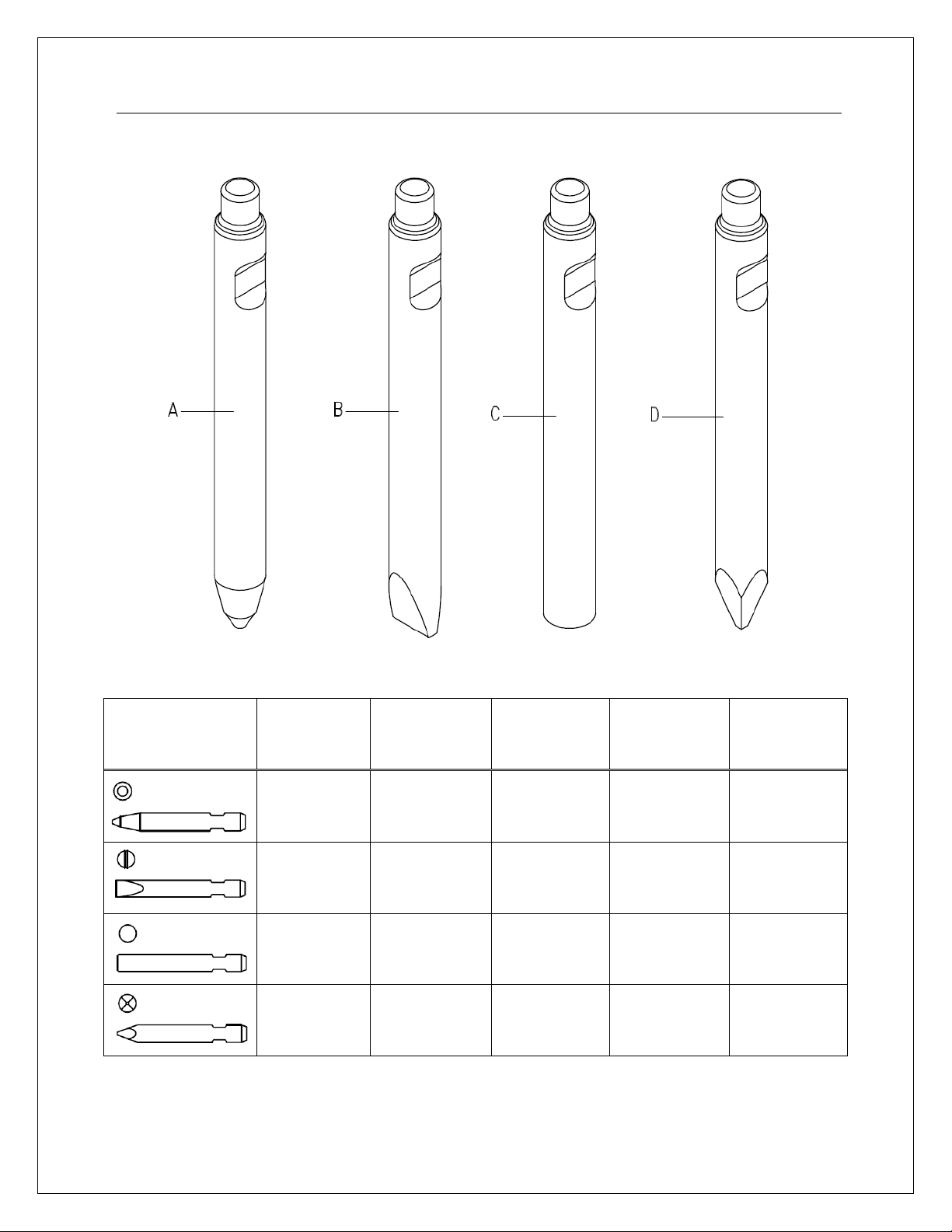
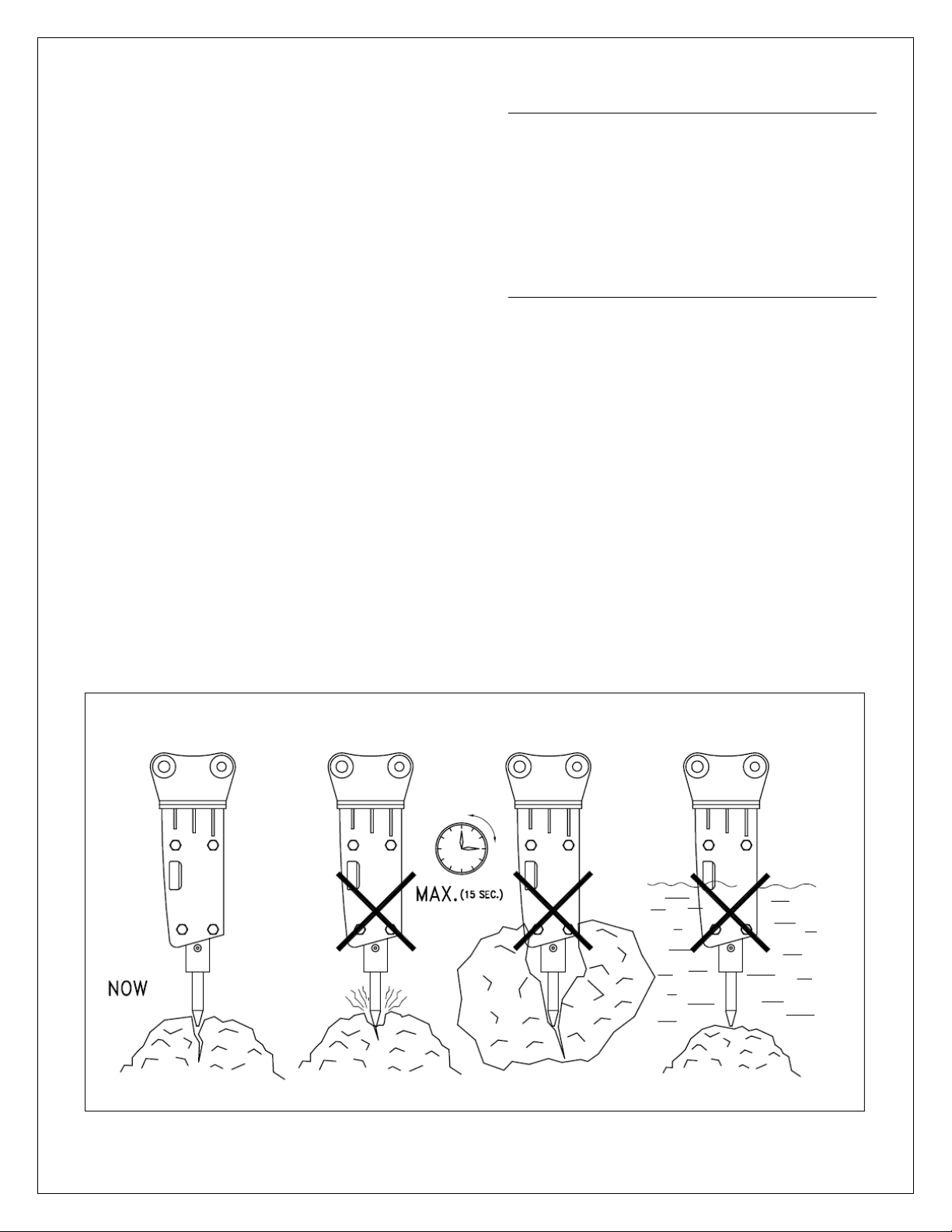
9) Chisel, cone, and moil
If the object does not break after fifteen
seconds, stop the beaker and change the
position of the tool. Leaving the tool in the
same position for more that fifteen seconds
will only make an indentation, which will fill
with dust and dampen the impact effect. This
will cause the tool to overheat.
10) When breaking concrete, hard ground, frozen
ground, or any similar material, never strike and
pry with the tool at the same time. This could
break the tool.
2.5 Operating Temperature
The operating temperature is -20°C~80⁰C. If the
temperature is lower than -20°C (-4°F), the
breaker and tool must be preheated before
starting to operate, in order to avoid breakage of
the accumulator membrane and the tool.
During operation they will remain warm.
2.6 Important Operation Points
a. Listen to the breaker‟s sound while you are
working.
If the sound becomes thinner and the impact
is less efficient, the tool is misaligned with
the material and/or there is not enough
“pressing” force on the tool.
Realign the tool and press the tool firmly
against the material.
b. The breaker, as a standard assembly must
not be used underwater.
If water fills the space where the piston
strikes the tool, a strong pressure wave is
generated and the breaker could be
damaged.

10
2.7 Storage
Long term storage
Observe the following points when the hammer is stored for a long period of time. This will protect
the vital parts of the attachment from rusting, and keeps the breaker ready for use whenever it is
needed.
1. The storage area must be dry.
2. The tool must be removed from the hammer.
3. The lower end of the piston, tool and the tool bushing must be well protected with grease.
4. Connections must be sealed with clean plugs to prevent oil leakage and dirt from getting into
the couplings.
5. The breaker must be stored in the vertical position.
6. Ensure that the breaker cannot fall over.

11
2.8 Mounting and Dismounting the Hammer
Removal from the carrier
1. Position the hammer horizontally on the floor and remove the tool.
2. Stop the carrier engine. Operate boom and hammer controls to release the trapped pressure
inside of the hoses. Wait ten minutes for the oil pressure to drop.
3. Close the hammer inlet and outlet lines. If quick couplers are used, disconnection
automatically closes the hammer lines.
4. Disconnect the hoses and plug them as well as the hammer inlet and outlet ports.
5. Remove the bucket pins and other parts.
6. The carrier can now be moved aside.
Installation
1. Install the hammer in the same manner as mounting a bucket, install bucket pins.
2. Connect the hoses. Hammer inlet port is marked on the back head with “IN” and the outlet
port is marked with “OUT”.
3. Open the hammer inlet and outlet lines.

12
2.9 Operation Pressure Settings
1) Operating Pressure
a. Stop the carrier engine.
b. Assemble the high pressure gauge to the high
pressure test port. Start the engine.
c. Set the tool of the breaker on something stable
(e.g. a thick steel plate).
d. Adjust the operating engine revolution and start
to operate the breaker.
e. Read the average pressure from the high
pressure gauge.
f. Operating pressure is pre-adjusted at the
factory and there should be no reason to adjust
it.
g. Stop the carrier and remove the gauge.
h. Tighten the plug of the pressure measuring
point.
2) Relief Valve
a. The relief valve is a safety device which is used
to protect the breaker when the pressure rises in
the hydraulic circuit.
b. The operating pressure of the breaker
determines the setting of the relief valve in the
pressure line.
c. The relief valve setting should be adjusted to the
specifications of each Vulcan model.
Model
Operating Pressure
VULCAN V3G
90 ~ 120 bar
Model
Relief Pressure
VULCAN V3G
140 ~ 160 bar

13
2.10 Hose and Pipe Specification
Model
Hose Assembly
Piping Line Size
Notes
IN
OUT
IN
OUT
V3G
PF ½„‟
PF ½„‟
PF ½„‟
PF ½„‟
2.11 Hydraulic Circuit

14
3. Lubrication
3.1 Manual Lubrication
* Grease interval
1. The tool shank and tool bushing must be well lubricated before installing the tool.
2. Apply 10 –20 strokes from the grease gun to the tool bushing and the tool at regular intervals.
3. Adapt the interval and amount of grease to minimize tool wear and keep it in good working condition.
Greasing should be done every hour.
Insufficient greasing or improper grease could cause:
-Abnormal wear of the tool bushing and the tool.
-Tool breakage.
Technical data:
-NLGI grade 2.
-Synthetic oil base with aluminum complex soap.
-Approximately 15% graphite copper solids to reduce metal to metal contact damage.
-Dropping point 260°C (500°F).
-Viscosity 15 cSt.
-Temperature range -30° ~ 230°C (-20°F ~ 450°F).

15
3.2 Hydraulic Oil
When the breaker is used continuously, the
temperature of the hydraulic oil normalizes at
a certain level, depending on the conditions
and the carrier. At this temperature, the
viscosity of the hydraulic oil should be 20 ~ 30
cSt (2.90~5.35°E).
The Vulcan hydraulic breaker must not be
started if the viscosity of the hydraulic oil is
above 1000 cSt (131°E) or operated when the
viscosity of the hydraulic oil is below 15 cSt
(5.35°E).
1) When the oil is too thick, the following
problems may occur.
a. Difficulty starting.
b. Stiff operation.
c. Irregularly and slow striking.
d. Danger of cavitations in the pumps and
hydraulic breaker.
e. Sticky valves.
f. Filter bypass, impurities in the oil not
removed.
2) When the oil is too thin, the following
problems may occur.
a. Efficiency losses (internal leaks).
b. Damage to gaskets and seal leaks.
c. Accelerated wearing of parts, caused
by decreased lubrication efficiency.
3) Special oils
In some cases special oils (e.g. biological
oils and non-inflammable oil) can be used.
Please observe following aspects when
considering the use of special oil:
The viscosity range in the special oil must
be within the range of 15 ~ 1000cSt
(2.35~131°E).

4) Cleanliness of the hydraulic oil
The hydraulic oil filter of the carrier will
clean the oil flowing through the
breaker.
The purpose of the oil filter is to remove
impurities from the hydraulic oil since
they accelerate component wear,
cause blockages and even seizure.
Impurities also cause the oil to
overheat and deteriorate.
Air and water are impurities in oil.
5) Oil filter
When working with the hydraulic
breaker, the carrier oil filter must fulfill
the following specifications:
a. The oil filter must be rated at 25
microns maximum.
b. The oil filter must be a standard
return line filter rated to maximum
working pressure.
c. The oil filter must have a volume flow
capacity of at least twice the
breaker‟s maximum flow.
d. The cooler must withstand a
dynamic pressure of 290 psi (20
bar).
6) If the carrier‟s oil cooler is too small, the
original cooler must be replaced with a
larger one or an auxiliary cooler must be
installed. The auxiliary hydraulic cooler
can be installed:
a. In front of the radiator, in which case
an additional fan is not required, i.e.
maximum rise of cooling air is 5°C
(40°F).
b. Any other suitable place, using a fan
either hydraulically of electrically
driven
7) Damage caused by hydraulic oil
contamination in the carrier and breaker
circuits causes:
a. The working life of the pumps to be
significantly shortened.
-Premature wear of the parts.
-Cavitation.
b. Valves to not function properly.
-Spools bind –premature wear of the
parts.
-Blocking of small holes.
c. Wear of the cylinders.
d. Reduced breaker efficiency.
-Premature wear of moving parts and seals.
-Danger of the piston seizing and
the oil overheating.
e. Shortened working life and reduced
efficiency of hydraulic oil.
-Oil overheats and the oil quality
deteriorates.
-Electro-chemical changes in the
hydraulic oil.

4. Maintenance
4.1 Removal and Installation of Tools and Tool Bushings
1) Removal
a. Place the breaker on level round.
b. Make sure that the carrier‟s transmission
is in neutral and the parking brake is
engaged.
c. Stop the engine.
d. Push the spring pin A as far as it will go.
e. Remove the tool pin B
f. Remove the tool.
g. Remove the tool bushing C.
Check the tool and the tool bushing for
wear.
2) Installation
a. Clean all parts
b. Apply MoS2 spray to the contact surfaces
of the tool holder bushing and front head.
c. Install the tool bushing C.
d. Install the tool pin B.
e. Install the tool and spring A.

18
4.2 Wear Limits of Tools and Tool Bushings
1) The normal clearance between the tool and the tool bushing is 4mm.
Check the wearing condition of the tool bushing and replace with a new tool bushing if clearance is out
of the specified range.
2) The tool bushing can be used continuously unless serious wear is found.
Model
Parts Name
New
Reject
Notes
V3G
Tool Bushing
53 mm
55 mm
Tool
53 mm
51 mm
Model
New
Reject
V3G
275
210 mm

19
4.3 Disassembling and Assembling the Hammer Assembly
1) Disassembling
a. Remove the tool and set the breaker
down vertically on the floor.
b. Disconnect the hoses and plug them and
the breaker inlet and outlet ports with
clean plugs.
c. Loosen the mounting bracket bolt B, lock
washer C, and nut D to remove the
mounting bracket A from the breaker.
d. Remove the front head joint bolt E, and
washer F.
e. Remove the side brackets.
2) Assembling
a. Set the breaker down vertically on the
floor.
b. Install the side brackets.
c. Install the washer, cap nut and housing
bolts.
d. Connect the mounting bracket by
tightening the mounting bracket bolts.
e. Remove the plugs from the hoses and
connect them to the breaker‟s inlet and
outlet ports.
f. Connect the pressure and return lines.
\
Table of contents
Popular Power Tools manuals by other brands

Makita
Makita DWT310 instruction manual

Makita
Makita AN453 instruction manual

Bosch
Bosch GSH 16-28 Original instructions

Parkside
Parkside PAMFW 20-LI A1 Translation of the original instructions

Würth
Würth 1952 004 320 Translation of the original operating instructions

Makita
Makita DTW284RTJ instruction manual