VULCANIC RADEB User manual

VULCANIC SAS Instruction Manual RADEB Type Radiator
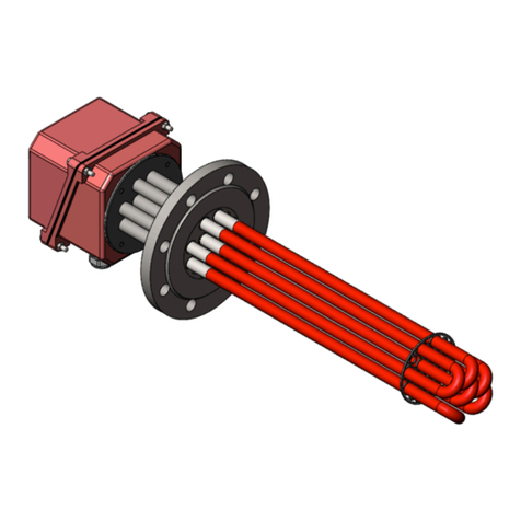
81080-11 Rev A dated 27/06/13 -UTEN RADEB Radiator
VULCANIC S.A.S.
48, rue Louis Ampère –Zone Industrielle des Chanoux
F –93330 NEUILLY SUR MARNE (France)
Tel.: (33) 01.49.44.49.20 –Fax: (33) 01.49.44.49.41
E-mail: catalogue-vulcanic@vulcanic.com
Web: www.vulcanic.com
VULCANIC S.A.
48, rue Louis Amp?re - Zone Industrielle des Chanoux
F 93330 NEUILLY / MARNE (France)
T?l. (33) 01.49.44.49.20 - Fax (33) 01.49.44.49.41
E.mail : catalogue-vulcanic@vulcanic.com
Web : www.vulcanic.com
RADIATOR SUB-ASSEMBLY
RADEB type
equipped with a flame-proof
connection box, for use in potentially
explosive zones
(Protection mode “Ex d”)
This document is an integral part of the product to which it refers.
Complete compliance with its contents is indispensable to maintaining the
guarantee and safety in potentially explosive zones.
In accordance with European directives a version of this instruction manual
must be supplied by the seller of the product to the final user, translated
into the language of the country of installation,
VULCANIC must be contacted if certain documents cited in the present
manual are not available, or if the information appearing in it does not
appear to be clear. If necessary a VULCANIC site technician must be
requested for commissioning.

Instruction Manual RADEB Type Radiator VULCANIC SAS
81080-11 Rev A dated 27/06/13 -UTEN RADEB Radiator -Page 2/5
1. AREA OF APPLICATION
This equipment is ATEX (European directive 94/9/CE) and IECEx certified:
- CE type examination certificate: INERIS 11 ATEX 0046
- Certificate IECEx INE 11.0021
It bears the marking:
II 2 G Ex d IIC T3 (or T4) Gb (depending on the auto ignition temperature of the
environment)
It is thus usable on the surface, in risk 1 and 2 zones, in a group IIA or IlB or IIC GAS
environment. It is designed to heat potentially explosive ambient air from -60°C or -20°C to
40°C or 60°C (depending on model), with 95% max. relative humidity, generally inside
industrial machines.
In the absence of a grill to protect against the dangers of hot surfaces it is not suitable for
heating rooms.
Its detailed technical characteristics and operating limits appear in the contractual
documentation whose number is restated on the rating plate, on the acknowledgement of
receipt of order and on the delivery note (reference, type, specification or drawing).
2. DESCRIPTION
This radiator comprises:
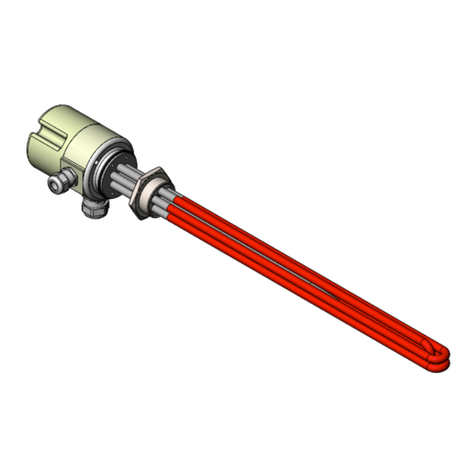
- A bundle of 1 to 6 tubular heating elements formed in single hairpin or 1 to 12 "cartridge"
type heating elements, with optional fins. The diameter of the heating elements can vary from
6.5 mm to 19 mm.
-A screw-in plug or flange mechanical fixing device.
- A box certified as flame-proof to Ex d IIC, protected to IP 55, equipped with its earth terminals
(for equipotential connection), which is equipped with one or more certified glands. The type
and size of cable entries are specified on the contractual drawing.
- Possibly a thermal safety device whose sensor measures the surface temperature of the
heating elements using a thermal bridge: thermostat or thermocouple or PT100.
- An adjustable setting thermal limiter, whose sensor also measures the surface temperature of
the heating elements.
- Possibly a perforated protective grill with 2 floor fixing feet, for room heating applications.
3. GENERAL PRECAUTIONS IN USE
- Opening the cover of the box in a potentially explosive environment is prohibited, when the
radiator is connected and supplied with electricity. The fitting and removal of screw-in glands
can only be done in the factory, under the responsibility of VULCANIC.
- It is essential that the gland packing must be compatible with the cables used. Verify the real
clamp diameter in the contractual documentation. Standard packings are designed for cables
with cylindrical external sheath. If necessary procure suitable packing.
- Removing the glands that have been installed in the manufacturer's factories is prohibited,
due to the risk of damaging the existing threads. When the glands are installed by the user
the glands must be chosen and fitted in accordance with the current rules (standard IEC/EN
60079-14, for example).
- When they are installed by the user the glands must be certified and compatible with the
holes in the box on which they are installed, depending on the diameter and pitch indicated
on the drawing or engraved nearby.
- Unused orifices must be blocked by an "Ex d" certified plug.
- Before closing the box, verify that the gas throttling surfaces (thread pitch or surface insert
between the body and its cover) do not show any mechanical damage or foreign particle.
Clean these surfaces if necessary.

VULCANIC SAS Instruction Manual RADEB Type Radiator
81080-11 Rev A dated 27/06/13 -UTEN RADEB Radiator –Page 3/5
- Closure of the cover can be eased by the use of a non-corrosive grease whose flash point is
greater than the maximum temperature reached by the box.
- Only apply electrical voltage to the installation after correctly closing the cover and
reinstalling the opening locking device.
4. SPECIAL CONDITIONS FOR SAFE USE IN POTENTIALLY EXPLOSIVE
ENVIRONMENTS
- In natural convection, the heating elements must be placed horizontally. They must not be
covered, so as to allow good air circulation. A free space of min. height 150 mm must be
present above and below the heater bundle.
- In forced convection the heating elements can be placed in all positions. Nevertheless a
minimum air speed must be guaranteed, and the electrical power supply must be slaved to
the presence of this flow rate, in compliance with the conditions appearing on the
manufacturer's contractual documents.
- When it exists the safety device must irreversibly cut the electrical power supply in the event
of a fault, independently of that of the regulation, which necessitates human intervention to
rest the installation after seeking the cause of the tripping out. Its setting is a maximum of
195°C in class T3 and 130°C in class T4. Its interpretation must have fast, positive action; it
must act directly on the radiator's electrical power supply, and must not be relayed by
software. Failing this the safety circuit must have a minimum integrity level of SIL 1 as
required by standard EN 50495.
- When the radiator sub-assembly includes a device to limit the surface temperature of its
heating elements, this must be duplicated by the safety device described above. The limiting
device is preset by VULCANIC to a setting that avoids the surface of the elements reaching a
temperature of 195°C en class T3 and 130°C in class T4, in the most unfavourable normal or
accidental operating conditions. This setting depends on the response time and differential of
this device.
- In no case must the adjustment of the limiting and safety settings, done in the VULCANIC
factories, be modified.
- In the absence of a temperature safety device, the user must provide monitoring of the
supply voltage (which must not exceed the rated voltage by more than 10%), and the
ambient temperature of the box (which must not exceed 40°C or 60°C depending on the
model).
The quality of the atmosphere in which the radiator is installed must be compatible with the
austenitic stainless steel making up the sheath of the heating elements, so as not to damage
them by corrosion.
- The specifications of installation standard IEC/EN 60079-14 must be complied with (in
particular for monitoring of the radiator electrical insulation), as well as the current national
standards. A fall in insulation could be a forewarning of loss of sealing of the heating
elements, which necessitates an immediate switching off of the electrical power supply.
- The terminal box cover must not be opened in a potentially explosive atmosphere
5. ELECTRICAL CONNECTION
This connection must take place when the voltage is switched off.
5-1 -Removing the cover: Remove the 4 fixing screws and extract the cover.
5-2 -After introducing the cable through the gland connect the two or three phases to the
terminals according to the diagram attached to the equipment.
Warning: These electrical couplings are generally made in the VULCANIC factories.
Modifying them is formally prohibited.
5-3 -The internal and external earth terminals must be connected to the installation earth.

Instruction Manual RADEB Type Radiator VULCANIC SAS
81080-11 Rev A dated 27/06/13 -UTEN RADEB Radiator -Page 4/5
5-4 -Verify that all the connections are correctly tightened.
5-5 -Tighten the gland bushing(s) to seal the cable sheath.
5-6 -Replace the cover, engaging it completely, (to comply with the seal length on the flame-
proof interstices).
5-7 -Fully screw in and tighten the 4 fixing screws.
6. COMMISSIONING AND OPERATION
Work on this equipment can only be done by qualified personnel. The installer must verify that
the equipment is suited to the zone classification and the characteristics of the different
inflammable substances.
Check that the cold insulation resistance is greater than 2 megohms and that the dielectric
strength is greater than 2 V + 1000 V for one second (V = nominal supply voltage). Failing
this, the radiator must not be used.
Only switch on after having correctly reclosed the cover; check the current consumed on each
phase immediately.
After stabilisation of the maximum operating temperature, set the leakage current monitoring
device threshold (differential circuit breaker or insulation detector) about 10% above the
values read, however without exceeding the values indicated in paragraph 7.4 of standard
EN 60079-14.
NOTE: The minimum insulation and strength values must be checked cold after a long
period switched off, because they guarantee the quality of the heating elements, so
reducing the risk of a spark appearing.
Any safety thermostat, not accessible to users, is set in the factory to the maximum setting
allowing compliance with the ATEX directive, without, however, exceeding the following
values: T4 = 130 °C and T3 = 195 °C.
Any limiting thermostat is always set to a setting less than that of the safety thermostat, so as to
limit the surface temperature of the heating elements in the event of malfunction (destruction
of exchange conditions or abnormal increase in the supply voltage).
7. MAINTENANCE:
The inspection and maintenance of ATEX electrical equipment is controlled by standard EN
60079-17.
7-1 -After 50 hours operation verify that the connections are still well tightened (for opening and
closing, see § 5 above).
7-2 -Check that the heater bundle and any protective grill are neither dusty nor corroded
(remove the dust if necessary).
7-3 -After a long period switched off verify the insulation and dielectric strength values
described in § 6.
Any repair related to the protection mode must be the subject of a prior agreement with
VULCANIC. It shall be done by VULCANIC or with its prior written authorisation or that of a
notified body, in compliance with ATEX regulations.
The cover fixing screws must be 8.8 quality.
If grease is used to ease fitting of the covers, it must be non-corrosive and non-hardening.
WARNING: the interstices and diametral clearances of the flame-proof joints that served for
certification could be less than the limit values in table 2 of the standard
IEC/ EN 60079-1. Contact the manufacturer before any repair of these joints.

VULCANIC SAS Instruction Manual RADEB Type Radiator
81080-11 Rev A dated 27/06/13 -UTEN RADEB Radiator –Page 5/5
8. GUARANTEE
Our guarantee is compliant with the Electric Construction inter-trade association agreements
and our general sales conditions. We guarantee the compliance of the equipment and any
surface treatments, as defined in our documents.
Damage caused by:
- Non-compliance with the operating limits,
- Wear caused by lack of maintenance, shocks, clumsiness or the inexperience of the user,
- Corrosion or clogging phenomena,
- Non compliance with the present instruction manual, good engineering practice and
legislation,
will not engage our responsibility.
Table of contents
Other VULCANIC Heater manuals
Popular Heater manuals by other brands

Master
Master B100ECA owner's manual

Olimpia splendid
Olimpia splendid CALDO CRYSTAL Instructions for installation, use and maintenance

Vitek
Vitek VT-1703 Manual instruction

Grill'D
Grill'D Aurora 180 Short Operation manual

HOMCOM
HOMCOM 824-051V90 Assembly & instruction manual

ARDES
ARDES AR4W08P Instructions for use