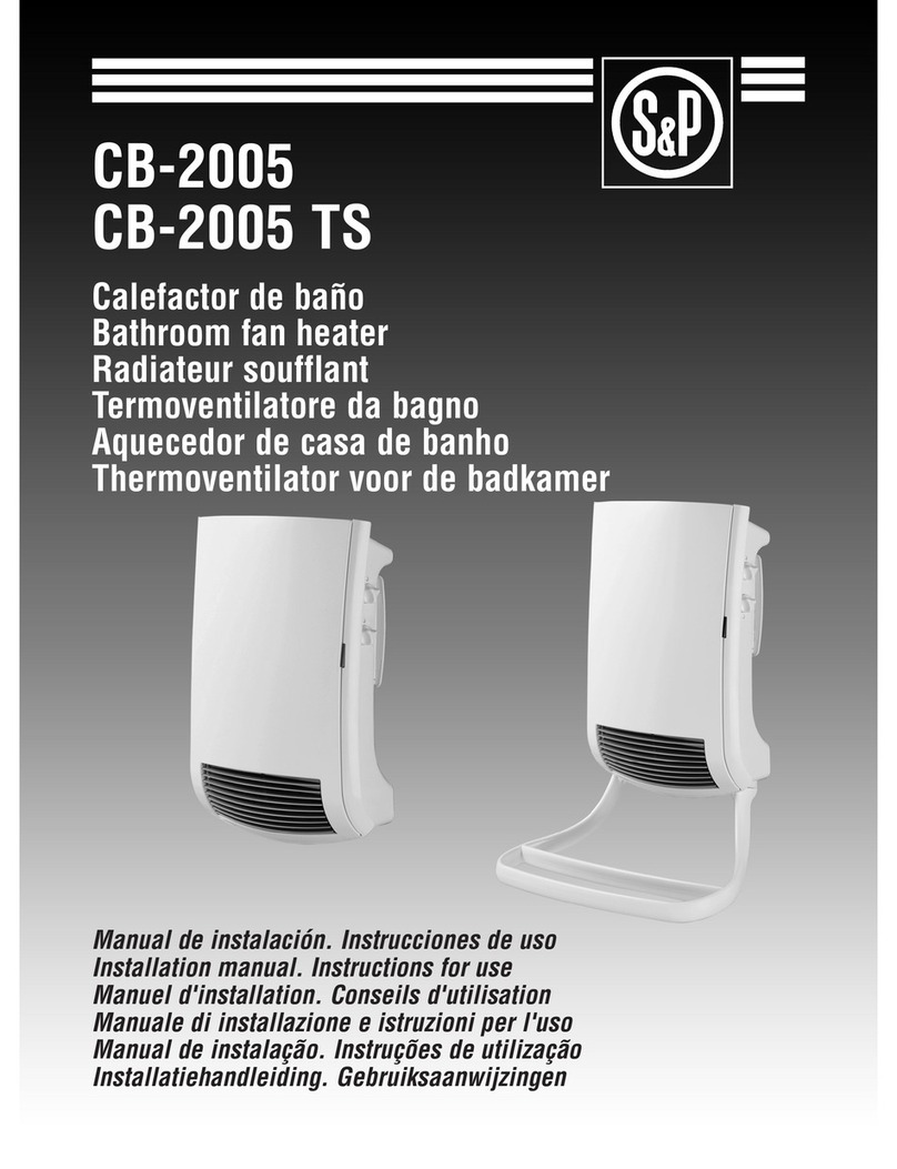
Soler & Palau EMIBLUE-A User manual

1
EMIBLUE - A
Emisor con fluido
Oil wall mounted radiator
Radiateur à inertie avec fluide
Emissor com fluído
Manual de instalación. Instrucciones de uso
Installation manual. Instructions for use
Manuel d'installation. Conseils d'utilisation
Manual de instalação. Instruções de uso

2

3
4 N
6 N
8 N
10 N
12 N
140
140
140
140
140
162
324
486
648
810
130
130
130
130
130
432
594
756
918
1080
Modelo / Model
Modele

4

5
ESPAÑOL
INDICE
1. GENERALIDADES . . . . . . . . . . . . . . . . . . . . . . . . . . . . . . . . . . . 6
2. INSTRUCCIONES IMPORTANTES. . . . . . . . . . . . . . . . . . . . . . . 6
3. INSTALACIÓN. . . . . . . . . . . . . . . . . . . . . . . . . . . . . . . . . . . . . . . 7
4. MANDOS DE CONTROL. (Fig. 9). . . . . . . . . . . . . . . . . . . . . . . . 8
5. MODOS DE FUNCIONAMIENTO . . . . . . . . . . . . . . . . . . . . . . . . 9
6. PUESTA EN MARCHA Y FUNCIONAMIENTO . . . . . . . . . . . . . . 9
7. MANTENIMIENTO . . . . . . . . . . . . . . . . . . . . . . . . . . . . . . . . . . 10
8. ASISTENCIA TÉCNICA. . . . . . . . . . . . . . . . . . . . . . . . . . . . . . . 11
9. PUESTA FUERA DE SERVICIO Y RECICLAJE . . . . . . . . . . . . 11

6
1. GENERALIDADES
Le agradecemos la confianza que nos ha depositado mediante la compra
de este emisor. Usted ha adquirido un producto de calidad que ha sido
totalmente fabricado según las reglas técnicas de seguridad reconocidas
y conformes a las normas de la CE.
La serie “EMIBLUE” de emisores S&P presenta un diseño funcional, incor-
pora un aceite especial diatérmico de alta duración y gran inercia térmica,
lo que les permite conservar el calor durante mucho tiempo. Están dota-
dos de termostato electrónico de gran precisión que desconecta el apa-
rato cuando se alcanza la temperatura de confort seleccionada, con el
consiguiente ahorro de energía.
La serie “EMIBLUE” está compuesta por los siguientes modelos:
Sírvase leer atentamente estas instrucciones, antes de la instalación y pues-
ta en funcionamiento, posteriormente guárdelas para futuras referencias.
Rogamos compruebe el perfecto estado y funcionamiento del aparato al
desembalarlo ya que cualquier defecto de origen que presente, está
amparado por la garantía S&P.
2. INSTRUCCIONES IMPORTANTES
ADVERTENCIAS DE SEGURIDAD E INSTALACIÓN
- El emisor no debe estar situado justamente debajo o encima de una base
de toma de corriente.
- Para instalación en cuartos de baño, el aparato deberá colocarse de
manera que los dispositivos de mando (interruptor, termostato) no pue-
dan ser tocados por una persona que esté en la bañera o ducha. El emi-
MODELO
EMIBLUE-4A
EMIBLUE-6A
EMIBLUE-8A
EMIBLUE-10A
EMIBLUE-12A
4
6
8
10
12
500
750
1000
1250
1500
400x95x570
560x95x570
720x95x570
880x95x570
1040x95x570
Nº
ELEMENTOS
POTENCIA
(w)
DIMENSIONES
L x A x H (mm.)

7
sor debe instalarse fuera del volumen de protección (Fig. 6)
- No cubrir el emisor con objetos o prendas que impidan la libre circula-
ción del aire. Si se cubre existe el riesgo de sobrecalentamiento.
- No usar el emisor para secar ropa por riesgo de incendio.
- No manipule el aparato con las manos mojadas.
- Siempre que realice la limpieza, tenga la precaución de desconectar el
aparato.
- La instalación deberá ser realizada por un técnico electricista.
- Este aparato no está destinado para ser usado por personas (incluidos
niños) cuyas capacidades físicas, sensoriales o mentales estén reduci-
das, o carezcan de experiencia o conocimiento, salvo si han tenido
supervisión o instrucciones relativas al uso del aparato por una persona
responsable de su seguridad.
- Los niños deberán ser supervisados para asegurar que no juegan con el
aparato.
IMPORTANTE: ESTOS APARATOS DEBERÁN CONECTARSE A UNA
TOMA DE TIERRA
- En caso de conexión fija, se debe colocar un dispositivo entre el aparato
y la red que garantice la desconexión con una distancia de abertura de los
contactos que permita la desconexión completa en las condiciones de la
categoría de sobretensión III, de acuerdo con la normativa de instalación.
- Al instalar el emisor asegurar que el cable de conexión nunca pueda
estar en contacto con una zona caliente del aparato.
- Si el cable de alimentación está dañado, debe ser substituido en uno de
nuestros talleres de reparación o por personal similar cualificado con el
fin de evitar un peligro.
- Este aparato se ha llenado con una cantidad de aceite especial exacta-
mente determinada. En caso de aparecer fugas, solamente nuestros
talleres oficiales de reparación pueden efectuar el arreglo del mismo.
- Cuando el emisor sea desechado, se debe hacer cumpliendo con la nor-
mativa vigente de productos que contengan aceite.
3. INSTALACIÓN
Estos emisores son aparatos para instalación fija, para su montaje se
seguirán las instrucciones que se detallan a continuación:
Emplazamiento
El emisor se ubicará en las zonas más próximas a los muros exteriores, los
rendimientos de emisión térmica quedan reflejados en el diagrama gráfico
de UBICACIÓN DE EMISORES ( Fig. 1 - 5 ).
En los cuartos de baño, los emisores deben instalarse fuera de los volú-
menes de prohibición y de protección ( Fig. 6 )

8
Montaje en la pared
El emisor se fijará a la pared mediante 2 soportes especialmente diseña-
dos, utilizando los tacos de PVC y los tornillos que se adjuntan en el
embalaje. Debe asegurarse que los tacos y los tornillos suministrados,
sean adecuados para el tipo de pared donde se va a colocar el emisor.
Nota: La distancia mínima entre el suelo y la base del emisor debe ser
de 100 mm.
Para instalar seguir la secuencia siguiente:
1- Marque la situación de los dos soportes superiores, según la Fig. 7/8,
respetando las distancias de la tabla que se adjunta. Utilice un soporte
como plantilla para marcar la situación de los dos agujeros. Efectúe los
taladros y coloque los tacos.
2- Fije los dos soportes del emisor mediante los cuatro tornillos suminis-
trados.
Conexión eléctrica
- Son emisores de instalación fija. En su conexionado a la red, deberán
tenerse en cuenta las directrices que se indican en el Reglamento de
Baja Tensión y las propias de cada país.
- La conexión fija deberá efectuarla un profesional.
- Estos aparatos deberán conectarse a una toma de tierra.
- Debe preverse en la instalación un interruptor magneto térmico u otro
dispositivo de desconexión omnipolar que interrumpa todas las líneas
de alimentación del aparato, este dispositivo debe presentar una sepa-
ración de contactos de al menos 3 mm en todos los polos.
- Al instalar el emisor asegurar que el cable de conexión nunca pueda
estar en contacto con una zona caliente del aparato.
- Proceder al conexionado a la red, comprobando que la tensión de la
misma coincida con la indicada en la placa de características del aparato.
4. MANDOS DE CONTROL. (Fig. 9)
El equipo consta de:
1.- Tecla StandBy:
Se utiliza para poner en marcha, parar el equipo, o bloquear el acceso.
2.- Led de estado asociado:
Indicará la situación según los casos:
* Led en color rojo fijo. Modo: Paro
En esta situación el equipo no trabajará en ningún caso, aunque sigue
alimentado a la red.

9
* Led en color verde: Modo Conectado.
En esta situación el equipo está conectado, pero el emisor no está con-
sumiendo energía (la resistencia no está funcionando).
* Led en color ámbar: Modo Conectado+Carga
En esta situación el equipo está conectado y calentando.
3.- Termostato.
Sirve para seleccionar la temperatura ambiente en el modo Confort.
4.- Tecla Mode:
Selecciona la función de trabajo. Dicha función se verá indicada según el
estado del Led asociado.
5.- Led Mode:
Iluminado Fijo: Modo Confort
Iluminado intermitente: Modo Económico
Apagado: Modo Antihielo
5. MODOS DE FUNCIONAMIENTO
- En Modo Confort, el emisor mantendrá constante la temperatura
ambiental para los horarios de ocupación, según la posición selecciona-
da mediante el mando del termostato.
- En Modo Económico, el emisor mantendrá automáticamente una tem-
peratura ambiente 3,5 ºC por debajo de la seleccionada en el modo
Confort.
- En Modo Antihielo, el emisor no funcionará a excepción de que la tem-
peratura ambiente descienda por debajo de los 7ºC, entrando en fun-
cionamiento, únicamente para evitar que dicha temperatura baje. Este
mecanismo es especialmente útil en lugares donde se alcanzan bajas
temperaturas y es fácil que se hiele el agua de las tuberías, etc.
6. PUESTA EN MARCHA Y FUNCIONAMIENTO
1.- Pulse la tecla de StandBy hasta que el led asociado cambie al color
verde o ámbar.
2.- Pulse la tecla MODE hasta que el led asociado quede iluminado fijo.
3.- Gire el mando del termostato en el sentido de las agujas del reloj hasta
el tope (el led de estado deberá estar en color ámbar).
4.- Una vez la habitación haya alcanzado la temperatura deseada, gire

10
lentamente el mando del termostato en el sentido contrario a las agujas
del reloj, hasta que el led de estado se ponga en color verde. A partir de
ese momento, el aparato se conectará y desconectará automáticamente
manteniendo constante la temperatura ambiente seleccionada.
5.- Para detener el funcionamiento del equipo, pulsar la tecla de StandBy
(led de estado en rojo).
6.- Función bloqueo de teclado. Para evitar manipulaciones no deseadas,
se puede bloquear el acceso al equipo de forma que no se pueda modifi-
car ningún ajuste ni pulsando ninguna de las dos teclas, ni girando el
mando del termostato. Para ello, se debe mantener pulsada la tecla
StandBy (1), durante 10 segundos. El bloqueo de las teclas se confirma
mediante un parpadeo rápido en el led asociado (2). Para desbloquear,
simplemente volver a mantener de nuevo 10 segundos pulsada la tecla
StandBy (1). Un nuevo parpadeo del led nos indica que se ha desbloque-
ado el acceso.
Nota: Si se produjera alguna perturbación, el sistema de desconexión
por sobrecalentamiento, desconectará automáticamente el aparato
y este dejará de calentar. Seguidamente siga las siguientes indicaciones
para rearmarlo:
- Pare el aparato pulsando la tecla StandBy (led de estado en rojo).
- Desconéctelo de la red eléctrica.
- Deje enfriar el aparato durante unos 30 minutos.
- Revise que no haya ninguna obstrucción que impida la libre circula-
ción del aire.
- Vuelva a pulsar la tecla StandBy (led de estado en verde o ámbar).
- Si después de estos controles el aparato no funciona normalmente,
le rogamos que acuda a la amplia red de Servicios Oficiales S&P.
7. MANTENIMIENTO
Los emisores S&P no necesitan de un especial mantenimiento, sin embar-
go, le aconsejamos:
1- Mantener los pasos de aire limpios.
2- Quitar periódicamente el polvo del emisor con un paño suave seco.
3- En caso de mucha suciedad limpiar con un paño suave impregnado
con un detergente no abrasivo.
4- Limpiar siempre en frío y evite usar disolventes.

11
8. ASISTENCIA TÉCNICA
La extensa red de Servicios Oficiales S&P garantiza una adecuada asis-
tencia técnica.
En caso de observar alguna anomalía en el aparato, rogamos se ponga en
contacto con cualquiera de los servicios oficiales mencionados, donde
será debidamente atendido.
Cualquier manipulación efectuada por personas ajenas a los Servicios
Oficiales S&P nos obligaría a cancelar su garantía.
Para aclarar cualquier duda con respecto a los productos S&P diríjase a la
Red de Servicios Post Venta si es en territorio español, o a su distribuidor
habitual en el resto del mundo. Para su localización puede consultar la
página WEB www.solerpalau.com
9. PUESTA FUERA DE SERVICIO Y RECICLAJE
- En caso de puesta en fuera de servicio, aunque sea de forma temporal,
es aconsejable conservar el aparato en lugar seco y libre de polvo, dentro
de su embalaje original.
- La normativa de la CEE y el compromiso que debemos adquirir con las
futuras generaciones, nos obligan al reciclado de materiales; le rogamos
que no olvide depositar todos los elementos sobrantes del embalaje en los
correspondientes contenedores de reciclaje, así como de llevar los apara-
tos sustituidos al Gestor de Residuos más próximo.
EL FABRICANTE NO SE HACE RESPONSABLE DE LOS DAÑOS PRODU-
CIDOS A PERSONAS Y/O COSAS DEBIDOS AL INCUMPLIMIENTO DE
ESTAS ADVERTENCIAS.
S&P SE RESERVA EL DERECHO A MODIFICACIONES DEL PRODUCTO
SIN PREVIO AVISO.

12
ENGLISH
INDEX
1. GENERALITIES . . . . . . . . . . . . . . . . . . . . . . . . . . . . . . . . . . . . 13
2. IMPORTANT INSTRUCTIONS . . . . . . . . . . . . . . . . . . . . . . . . . 13
3. INSTALLATION . . . . . . . . . . . . . . . . . . . . . . . . . . . . . . . . . . . . . 14
4. CONTROLS . . . . . . . . . . . . . . . . . . . . . . . . . . . . . . . . . . . . . . . 15
5. OPERATION MODES . . . . . . . . . . . . . . . . . . . . . . . . . . . . . . . . 16
6. START-UP AND OPERATION . . . . . . . . . . . . . . . . . . . . . . . . . . 16
7. MAINTENANCE . . . . . . . . . . . . . . . . . . . . . . . . . . . . . . . . . . . . 17
8. TECHNICAL ASSISTANCE. . . . . . . . . . . . . . . . . . . . . . . . . . . . 17
9. REMOVAL FROM SERVICE, DISPOSAL AND RECYCLING . . 17

13
1. GENERALITIES
We appreciate the trust that you have put in us by buying this radiator. You
have acquired a product of quality which has been made totally according
to the recognized technical security regulations and in agreement with the
rules of the EC.
The series EMIBLUE of radiators S&P presents a functional design, incor-
porating a special long standing diathermic oil with a high thermal inertia,
which allows it to conserve the heat over a long period of time. They are
fitted with a high precision electronic thermostat which disconnects the
appliance when it reaches the temperature of comfort selected, with the
resulting energy saving.
The series EMIBLUE is made up of the following models:
It will help you to read these instructions carefully before it is installed and
turned on, and afterwards keep them for future reference.
We ask you to check that the appliance is in perfect condition and func-
tions well when you unpack as any defects that are present then are cove-
red by the guarantee S&P.
2. IMPORTANT INSTRUCTIONS
SAFETY AND INSTALLATION WARNINGS
- The radiator must not be situated exactly below or above an electrical
socket.
- For installation in bathrooms, the appliance must be placed in such a way
that the control mechanisms (switch, thermostat) cannot be touched by
anybody in the bath or shower. The radiator must be installed away from
the protection volume. (Fig. 6)
- Do not cover the radiator with objects or clothes which may impede free
circulation of air. If you cover it you run the risk of it over-heating.
MODEL
EMIBLUE-4A
EMIBLUE-6A
EMIBLUE-8A
EMIBLUE-10A
EMIBLUE-12A
4
6
8
10
12
500
750
1000
1250
1500
400x95x570
560x95x570
720x95x570
880x95x570
1040x95x570
Nº
ELEMENTS
POWER
(w)
DIMENSIONS
W x D x H (mm.)

14
- Do not use the radiator to dry clothes as it is a fire-hazard.
- Do not handle the appliance with wet hands.
- When you clean it always take the precaution of disconnecting the
appliance.
- It must be installed by a technical electrician.
- This appliance is not suitable for use by persons (including children)
whose physical, sensorial or mental capacities are impaired, or who lack
the appropriate experience and knowledge necessary for its use, unless
acting under the supervision or instructions of a person responsible for
their safety.
- Children should be kept under supervision to ensure they do not play
with the appliance.
IMPORTANT: THESE APPLIANCES MUST BE PROPERLY EARTHED.
- In case of fixed connection, a device between the appliance and the main
supply should be placed to guarantee the disconnection with an opening dis-
tance of the contacts that permits the complete disconnection in the category
III of overtension conditions, according to the installation regulation.
- When installing the radiator, make sure that the connection cable can
never be in contact with a hot area of the appliance.
- If the supply cable is damaged it must be replaced by one of our service
centres or by people similarly qualified in order to avoid any danger.
- This appliance has been filled with a precisely determined amount of
special oil. If leaks appear, only our official repair service engineers can
mend them.
- When scrapping the heater, follow the regulations concerning the dispo-
sal of oil.
3. INSTALLATION
These radiators are for fixed installation and in order to install them follow
the instructions below:
Location
The radiator must be located as close as possible to exterior walls; the
thermal emission efficiency is shown in the graphic design RADIATOR
PLACEMENT (Fig. 1 – 5).
In bathrooms, the radiators must be installed beyond the prohibited and
protection limits (Fig. 6)
Wall installation
The radiator is fixed to the wall by 2 specially designed supports, using the
PVC rawl-plugs and the screws which are enclosed in the packaging. You

15
should make sure that the rawl-plugs and the screws provided are suita-
ble for the type of wall on which the radiator is going to be located.
Please note: The minimum distance between the floor and the base of
the radiator must be 100mm.
To install follow the procedure below:
1- Mark the location of the upper supports according to Fig. 7/8, following
the distances in the attached table. Use a support as a template to mark
where the holes should be. Drill the holes and put in the rawl-plugs.
2- Fix the two supports for the radiator with the four screws provided.
Electrical connection
- They are fixed installation radiators. In order to connect them to the
mains circuit, you should take into account the guidelines which are
shown in the Low Voltage Regulations and those for each particular
country.
- The fixed connection should be made by a professional.
- These appliances must be earthed.
- There must be a thermal magnetic switch or other device that comple-
tely disconnects the electricity supply from the appliance; this device
must have a separation of the contacts of at least 3mm at all the poles.
- When installing the radiator, make sure that the connecting cable can
never be in contact with a hot area of the appliance.
- Proceed with the connection to the mains circuit, making sure that the
voltage is the same as that shown on the appliance registration plate.
4. CONTROLS (Fig. 9)
The equipment consists of:
1. - StandBy key:
Use to start, stop or block access.
2. - Status LED:
Will indicate the situation according to status:
* LED solid red. Mode: Stopped
In this situation, the equipment will not work under any circumstances, alt-
hough it continues feeding the network.
* LED green: Connected mode.
In this situation, the equipment is connected, but the radiator is not using
energy (the resistance is off).
* LED amber: Connected+Load mode
In this situation, the equipment is connected and heating.

16
3. - Thermostat.
To select ambient temperature in Comfort mode.
4. - Mode key:
Selects the work function. This function will be indicated according to the
status of the associated LED.
5. - LED Mode:
Solid illumination: Comfort mode
Flashing illumination: Economy mode
Off: Anti-freeze mode
5. OPERATION MODES
- In Comfort Mode, the transmitter will keep the ambient temperature
constant for the time the area is occupied, according to the position selec-
ted on the thermostat control.
- In Economy Mode, the transmitter will automatically maintain an
ambient temperature 3.5 ºC below the temperature selected in the
Comfort mode.
- In Anti-freeze mode, the transmitter will not work unless the ambient
temperature falls below 7ºC, working only to avoid the temperature falling.
This mechanism is especially useful in places with low temperatures where
it is easy for water in the pipes, etc. to freeze
6. START-UP AND OPERATION
1.- Press the StandBy key until the LED associated to it changes to green
or amber.
2.- Press the MODE key until the LED associated to it shines a solid colour.
3.- Turn the thermostat control clockwise to its limit (the status LED should
be amber).
4.- Once the room has reached the desired temperature, turn the ther-
mostat control anticlockwise slowly, until the status LED is green. From
that moment, the device will switch on and off automatically, maintaining
the selected ambient temperature constant.
5.- To turn off the equipment, press the StandBy key (LED_status red led).
6.- Keyboard lock function. To avoid undesired manipulation, it is possible
to block access to the equipment so that it is not possible to modify any
adjustment by pushing either of the two keys or turning the thermostat
control. To do this, press the StandBy key (1), continuously for 10 seconds.
The keyboard locking will be confirmed by rapid flashing of the associated
LED (2). To unlock the device, just press the StandBy key (1) again for 10
seconds. The flashing LED will indicate that access has been unlocked.
Note: If there is any disturbance, the overheating disconnection system

17
will automatically disconnect the appliance
and it will stop heating. To reset it, follow these instructions:
- Stop the appliance by pressing the StandBy key (Status LED_red).
- Disconnect the equipment from the mains
- Let the appliance cool for about 30 minutes.
- Make sure that there is no obstruction to free air flow.
- Press the StandBy key again (status LED green or amber).
- If, after these actions, the appliance does not work normally, please
contact the wide S&P Official Technical service network.
7. MAINTENANCE
The S&P radiators do not need specific maintenance, however we suggest:
1- Keep the air passages clean.
2- Dust the radiator periodically with a soft dry cloth.
3- When it is very dirty, clean with a cloth with an un-abrasive detergent.
4- Always clean when cold and avoid using solvents.
8. TECHNICAL ASSISTANCE
The extensive Official Services S&P Network guarantees correct technical
assistance. If you see an anomaly in the appliance, please get in touch with
any of the official services mentioned above, where you will be duly dealt with.
Any work done by those not pertaining to the S&P Official Services will
oblige us to annul the guarantee.
For any questions regarding S&P products, contact one of our After
Salesoffices (Spain only) or your dealer (rest of world). To find your nearest
S&P dealer, visit our website at www.solerpalau.com
9. REMOVAL FROM SERVICE, DISPOSAL AND RECYCLING
- When not using the appliance for extended periods of time, it
should be returned to its original packaging and stored in a dry,
dust-free place.
- EU regulations and our commitment to future generations obli-
ge us to recycle used materials; please remember to dispose of
all superfluous packaging materials at the appropriate recycling points,
and to drop off obsolete equipment at the nearest waste management
point.
THE MANUFACTURER CANNOT BE HELD RESPONSIBLE FOR DAMAGE
TO PERSONS AND/OR PROPERTY RESULTING FROM THE FAILURE TO
COMPLY WITH THESE INSTRUCTIONS.
S&P RESERVES THE RIGHT TO MODIFY THE PRODUCT WITHOUT
PRIOR NOTICE.

18
FRANÇAIS
INDEX
1. GÉNÉRALITÉS . . . . . . . . . . . . . . . . . . . . . . . . . . . . . . . . . . . . . 19
2. INSTRUCTIONS IMPORTANTES . . . . . . . . . . . . . . . . . . . . . . . 19
3. INSTALLATION . . . . . . . . . . . . . . . . . . . . . . . . . . . . . . . . . . . . 20
4. COMMANDES . . . . . . . . . . . . . . . . . . . . . . . . . . . . . . . . . . . . . 21
5. MODES DE FONCTIONNEMENT. . . . . . . . . . . . . . . . . . . . . . . 22
6. MISE EN MARCHE ET FONCTIONNEMENT . . . . . . . . . . . . . . 22
7. MAINTENANCE . . . . . . . . . . . . . . . . . . . . . . . . . . . . . . . . . . . . 23
8. ASSISTANCE TECHNIQUE . . . . . . . . . . . . . . . . . . . . . . . . . . . 23
9. MISE HORS SERVICE ET RECYCLAGE . . . . . . . . . . . . . . . . . . 24

19
1. GÉNÉRALITÉS
Nous vous remercions de la confiance que vous nous accordez en ache-
tant ce radiateur. Vous avez acheté un produit de qualité, entièrement
fabriqué selon les règles techniques de sécurité reconnues et conformes
aux normes de la CE.
La série EMIBLUE de radiateurs S&P présente un design fonctionnel, qui
comprend une huile spéciale diathermique de grande durée et inertie ther-
mique, ce qui permet de conserver la chaleur beaucoup plus longtemps.
Les radiateurs sont équipés de thermostat électronique de grande préci-
sion qui déconnecte l’appareil lorsqu’il a atteint la température choisie,
permettant ainsi une économie d’énergie.
La série EMIBLUE est composée des modèles suivants:
Prière de lire attentivement ces instructions avant l’installation et la mise en
service et de les garder ensuite pour de futures références.
Prière de vérifier l’état et le fonctionnement de l’appareil au déballage car
tout défaut d’origine est couvert par la garantie S&P.
2. INSTRUCTIONS IMPORTANTES
CONSIGNES DE SECURITE ET D’INSTALLATION
- Le radiateur ne doit pas être situé juste sur ou sous une base de prise de
courant.
- Pour installation en salles de bain, l’appareil devra être placé de façon à ce
que les dispositifs de commande (interrupteur, thermostat) ne soient pas
accessibles à une personne se trouvant dans la baignoire ou sous la
douche. Le radiateur doit être installé hors du volume de protection (Fig. 6)
- Ne pas couvrir le radiateur d’objets ou de vêtements gênant la libre cir-
culation de l’air, car dans ce cas, il existe un risque de surchauffe.
- Ne pas utiliser le radiateur pour sécher le linge ce qui pourrait provoquer
MODELE
EMIBLUE-4A
EMIBLUE-6A
EMIBLUE-8A
EMIBLUE-10A
EMIBLUE-12A
4
6
8
10
12
500
750
1000
1250
1500
400x95x570
560x95x570
720x95x570
880x95x570
1040x95x570
Nº
ELEMENTS
PUISSANCE
(w)
DIMENSIONS
L x A x H (mm.)

20
un incendie.
- Ne pas manipuler l’appareil avec les mains mouillées.
- Pour le nettoyage, débrancher toujours l’appareil.
- L’installation devra être effectuée par un technicien électricien.
- Cet appareil n'est pas destiné à être utilisé par des personnes (enfants
compris) dont les capacités physiques ou mentales sont réduites, ou qui
manquent d'expérience ou de connaissance, sauf si elles sont supervi-
sées ou ont reçu des instructions relatives à l'usage de l'appareil de la
part d'une personne responsable de leur sécurité.
- Les enfants devront être surveillés pour s'assurer qu'ils ne jouent pas
avec l'appareil.
IMPORTANT: CES APPAREILS DEVRONT ETRE BRANCHES À UNE
PRISE DE TERRE.
- En cas de montage fixe, prévoir un dispositif de coupure entre l'appareil
et le réseau électrique qui garantisse une ouverture entre contact permet-
tant une déconnection complète dans les conditions de la catégorie de
surtension III, conformément à la norme d'installation.
- En installant le radiateur, s’assurer que le câble de connexion ne puisse
jamais être en contact avec une zone chaude de l’appareil.
- Si le câble d’alimentation est endommagé, il doit être remplacé dans l’un
de nos ateliers de réparation ou par du personnel qualifié afin d’éviter les
dangers.
- Cet appareil est rempli d’une huile spéciale exactement déterminée. En
cas de fuite, seuls nos ateliers de réparation agréés peuvent effectuer la
réparation.
- Quand le radiateur sera à jeter, il faudra le faire conformément à la norme
en vigueur sur les produits contenant de l'huile.
3. INSTALLATION
Ces radiateurs sont des appareils destinés à l’installation fixe, il faudra
donc suivre les instructions détaillées ci-après.
Emplacement
Le radiateur est placé dans les zones les plus proches des murs exté-
rieurs, les performances d’émission thermiques sont rapportés dans le
diagramme graphique d’EMPLACEMENT DE RADIATEURS ( Fig. 1 - 5 ).
Dans les salles de bain, les radiateurs doivent être installés hors des volu-
mes interdits et de protection. ( Fig. 6 )
Montage au mur
Le radiateur sera fixé au mur à l’aide de 2 supports spécialement conçus
Table of contents
Languages:
Other Soler & Palau Heater manuals
Soler & Palau
Soler & Palau TLS-501 User manual

Soler & Palau
Soler & Palau COR-1000 NW 9 User manual

Soler & Palau
Soler & Palau SAHARA Series Installation instructions manual

Soler & Palau
Soler & Palau HE3 - 2000 User manual

Soler & Palau
Soler & Palau CB-2005 User manual

Soler & Palau
Soler & Palau TL-29 User manual

Soler & Palau
Soler & Palau COR-6-1000 N User manual
Popular Heater manuals by other brands
Heatstore
Heatstore HS1500C operating instructions

Steinbach
Steinbach Speedheat Waterpower 3600 user manual

Space-Ray
Space-Ray ADU25 Installation and operation instruction

EUROM
EUROM PD2100 manual

Webasto
Webasto DUAL TOP RHA-100 operating instructions

Jaga
Jaga Eyecatchers heatwaveextralarge Mounting instructions