VWR International 1915A User manual

VWR INTERNATIONAL, LLC
1915A 1925A
Installation and Operation Manual,
110 – 120 Voltage
11/5/2019

2 | Page
Pictured on Cover: 1915A left, 1925A right
Warning:This product contains chemicals, including triglycidyl isocyanurate, known to the State of
California to cause cancer as well as birth defects or other reproductive harm. For more
information, go to www.P65Warnings.ca.gov.
¡Advertencia! Este producto contiene sustancias químicas, incluido el triglicidil isocianurato, que el
estado de California sabe que causa cáncer, así como defectos de nacimiento u otros daños
reproductivos. Para obtener más información, visite www.P65Warnings.ca.gov.
Avertissement!Ce produit peut vous exposer à des produits chimiques, dont l'isocyanurate de
triglycidyle, reconnu par l'État de Californie pour provoquer le cancer, des anomalies congénitales
ou d'autres problèmes de reproduction. Pour plus d'informations, visitez le site
www.P65Warnings.ca.gov.

3 | Page
VWR General Purpose Incubator
110 – 120 Voltage
Large Capacity Models
Part Number (Manual): 4861765
Revised: November 5, 2019
Model Name Catalog Number
1915A 35962-062
1925A
35962-095
These units are CUE listed by TÜV SÜD as incubators for professional, industrial, or educational
use where the preparation or testing of materials is done at an ambient air pressure range of 22.14
– 31.3 inHg (75 – 106 kPa) and no flammable, volatile, or combustible materials are being heated.
These units have been tested to the following requirements:
CAN/CSA C22.2 No. 61010-1:2012
CAN/CSA C22.2 No. 61010-2-010:2015
UL 61010-2-010:2015
UL 61010-1:2012
EN 61010-1:2010
EN 61010-2-010:2014

4 | Page
TABLE OF CONTENTS
INTRODUCTION........................................................................................................................................... 5
Read this Manual ...................................................................................................................................... 5
Safety Considerations and Requirements ................................................................................................ 5
Contacting Assistance............................................................................................................................... 6
Engineering Improvements ....................................................................................................................... 6
Reference Sensor Device ......................................................................................................................... 7
RECEIVING YOUR UNIT.............................................................................................................................. 9
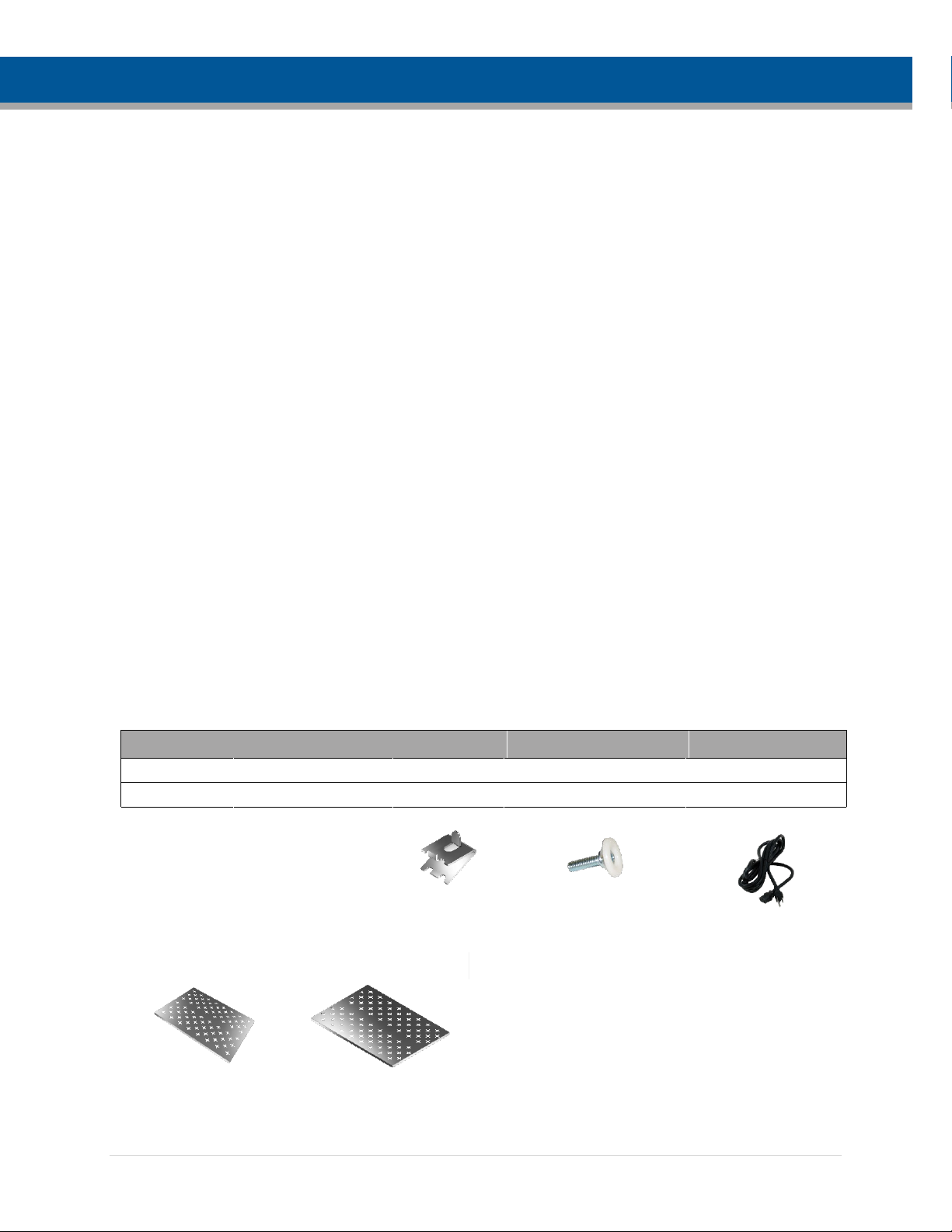
Inspect the Shipment ................................................................................................................................ 9
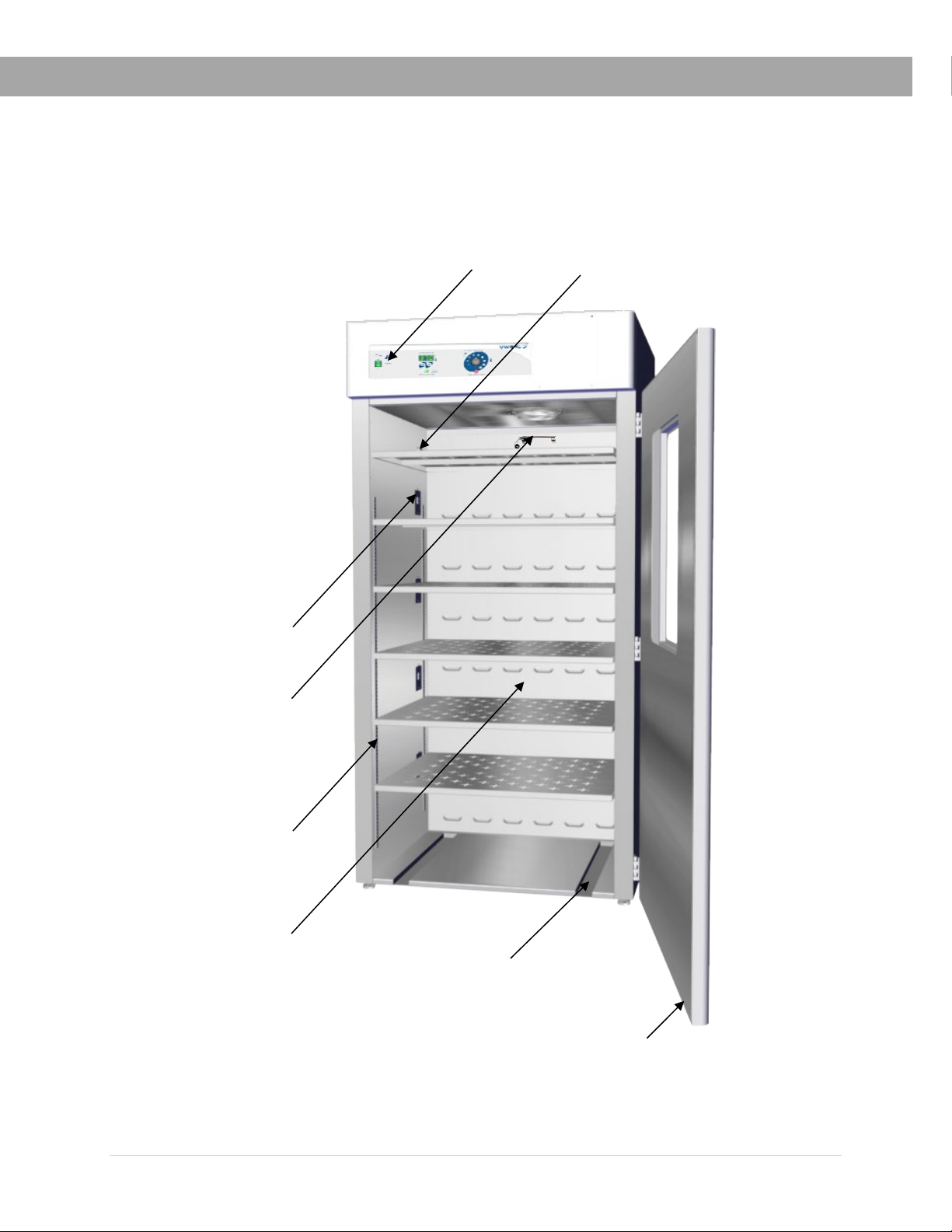
Orientation Images .................................................................................................................................. 10
Record Data Plate Information................................................................................................................ 13
INSTALLATION .......................................................................................................................................... 15
Installation Procedure Checklist.............................................................................................................. 15
Required Ambient Conditions ................................................................................................................. 16
Required Clearances .............................................................................................................................. 16
Power Source Requirements .................................................................................................................. 17
Lifting and Handling ................................................................................................................................ 18
Leveling ................................................................................................................................................... 18
Install the Incubator ................................................................................................................................. 19
Deionized and Distilled Water ................................................................................................................. 19
Installation Cleaning and Disinfecting ..................................................................................................... 19
Shelving Installation ................................................................................................................................ 20
Access Port ............................................................................................................................................. 20
GRAPHIC SYMBOLS................................................................................................................................. 21
CONTROL PANEL OVERVIEW................................................................................................................. 23
OPERATION ............................................................................................................................................... 25
Theory of Operation ................................................................................................................................ 25
Put the Incubator into Operation ............................................................................................................. 26
Set the Temperature Set Point................................................................................................................ 27
Set the Over Temperature Limit (OTL) ................................................................................................... 28
Loading Samples..................................................................................................................................... 29
Chamber Accessory Power Outlets ........................................................................................................ 29
Humidifying the Incubator ....................................................................................................................... 29
Condensation and the Dew Point............................................................................................................ 30
USER MAINTENANCE............................................................................................................................... 31
Cleaning and Disinfecting ....................................................................................................................... 31
Minimizing Contamination Exposure....................................................................................................... 32
Door Components ................................................................................................................................... 33
Electrical Components ............................................................................................................................ 33
Storing the Incubator ............................................................................................................................... 33
Calibrate the Temperature Display ......................................................................................................... 34
UNIT SPECIFICATIONS............................................................................................................................. 39
Weight ..................................................................................................................................................... 39
Dimensions.............................................................................................................................................. 39
Chamber Volume .................................................................................................................................... 40
Shelf Capacity ......................................................................................................................................... 40
Temperature............................................................................................................................................ 40
Power ...................................................................................................................................................... 40
PARTS LIST ............................................................................................................................................... 41

5 | Page
INTRODUCTION
READ THIS MANUAL
Failure to follow the guidelines and instructions in this user manual may create a protection
impairment by disabling or interfering with the unit safety features. This can result in injury or death.
Before using the unit, read the manual in its entirety to understand how to install, operate, and
maintain the unit in a safe manner. Ensure all operators are given appropriate training before the
unit begins service.
Keep this manual available for use by all operators.
SAFETY CONSIDERATIONS AND REQUIREMENTS
Follow basic safety precautions, including all national laws, regulations, and local ordinances in
your area regarding the use of this unit. If you have any questions about local requirements, please
contact the appropriate agencies.
SOPs
Because of the range of potential applications this unit can be used for, the operator or their
supervisors must draw up a site-specific standard operating procedure (SOP) covering each
application and associated safety guidelines. This SOP must be written and available to all
operators in a language they understand.
Intended Applications and Locations
These incubators are engineered for constant temperature, non-humidified general incubation
applications in professional, industrial, and educational environments. The units are not intended for
use at hazardous or household locations.
Power
Your unit and its recommended accessories are designed and tested to meet strict safety
requirements.
•The unit is designed to connect to a power source using the specific power cord type
shipped with the unit.
•Always plug the unit power cord into a protective earth grounded electrical outlet
conforming to national and local electrical codes. If the unit is not grounded properly, parts
such as knobs and controls can conduct electricity and cause serious injury.
•Do not bend the power cord excessively, step on it, or place heavy objects on it.
•A damaged cord can be a shock or fire hazard. Never use a power cord if it is damaged or
altered in any way.
•Use only approved accessories. Do not modify system components. Any alterations or
modifications to your unit not explicitly authorized by the manufacturer can be dangerous
and will void your warranty.

6 | Page
INTRODUCTION
CONTACTING ASSISTANCE
Please have the following information ready when calling or emailing Technical Support: the model
number and the serial number (see page 13).
TechnicalProduct[email protected]om
888.VWR.LINE (888.897.5463)
(610) 386-1700
VWR
Radnor Corporate Center
Building One
Suite 200
P.O. Box 6660
100 Matsonford Road
Radnor, PA 19087-8660
ENGINEERING IMPROVEMENTS
VWR continually improves all of its products. As a result, engineering changes and improvements
are made from time to time. Therefore, some changes, modifications, and improvements may not
be covered in this manual. If your unit’s operating characteristics or appearance differs from those
described in this manual, please contact VWR for assistance.

7 | Page
INTRODUCTION
REFERENCE SENSOR DEVICE
Must be purchased separately
A reference sensor device is required for calibrating the unit temperature display.
Reference devices must meet the following standards:
•Accurate to at least 0.1°C
The device should be regularly calibrated, preferably by a third party.
Temperature Probes
Use a digital device with wire thermocouple probes that can be introduced into the unit chamber
through the door space or access port. Select thermocouples suitable for the application temperature
you will be calibrating at.
Why Probes?
Reference readings taken outside the chamber using wire temperature probes avoid chamber door
openings. Openings disrupt the chamber temperature. Each disruption requires a minimum 1-hour
wait to allow the atmosphere to re-stabilize before continuing.
No Alcohol or Mercury Thermometers
Alcohol thermometers do not have sufficient accuracy to conduct accurate temperature calibrations.
Never place a mercury thermometer in the unit chamber. Always use thermocouple probes.
Temperature
Reference

8 | Page
INTRODUCTION
This page left blank

9 | Page
RECEIVING YOUR UNIT
INSPECT THE SHIPMENT
•When a unit leaves the factory, safe delivery becomes the responsibility of the carrier.
•Damage sustained during transit is not covered by the manufacturing defect warranty.
•Save the shipping carton until you are certain that the unit and its accessories function
properly.
When you receive your unit, inspect it for concealed loss or damage to its interior and exterior. If
you find any damage to the unit, follow the carrier’s procedure for claiming damage or loss.
1. Carefully inspect the shipping carton for damage.
2. Report any damage to the carrier service that delivered the unit.
3. If the carton is not damaged, open the carton and remove the contents.
4. Inspect the unit for signs of damage. Use the orientation images in this chapter as a reference.
5. The unit should come with an Installation and Operation Manual.
6. Verify that the correct number of accessory items has been included.
7. Carefully check all packaging for accessories before discarding.
Included Accessories
Model Shelves Shelf Clips Leveling Feet Power Cord
1915A 6 24 4 1
1925A
6
24
4
1
Shelves
1915A 1925A

10 | Page
RECEIVING
ORIENTATION IMAGES
Control Panel
Access Port
OTL Probe (Top)
Temperature Probe (Bottom)
Chamber Door
Incubation Chamber
Roller Bottle Apparatus
Wheel Groove
Shelf Standard Rail
Door Gasket
1915A
Chamber Outlet

11 | Page
RECEIVING
Control Panel
Access Port
OTL Probe (Top)
Temperature Probe (Bottom)
Chamber Door
Incubation Chamber
Roller Bottle Apparatus
Wheel Groove
Shelf Standard Rail
Door Gasket
1925A
Chamber Outlet

12 | Page
RECEIVING
Power Cord Inlet with Fuse Holder
Power Panel, Left Side of Units

13 | Page
RECEIVING
RECORD DATA PLATE INFORMATION
Record the unit model number and serial number below for future reference. Tech Support needs
this information to provide accurate help during support calls and emails.
•The data plate is located on the lower, left side of the unit, above the power inlet.
Date Plate Information
Model Number
Serial Number

14 | Page
RECEIVING
This page left blank

15 | Page
INSTALLATION
INSTALLATION PROCEDURE CHECKLIST
For installing the unit in a new workspace location.
Pre-Installation
Check that the required ambient conditions for the unit are met, page 16.
Check that the spacing clearance requirements are met, page 16.
•Unit dimensions may be found on page 39.
Check that a suitable electrical outlet and power supply is present, page 17.
Install the incubator in a suitable workspace location
Review the lifting and handling instructions, page 18.
Install the unit leveling feet, page 18.
Install the unit in its workspace location, page 18.
Set up the incubator for use
Clean and disinfect the unit and shelving (recommended), page 19.
Install the shelving, page 20.
Verify the port cap has been installed in the access port, page 20.

16 | Page
INSTALLATION
REQUIRED AMBIENT CONDITIONS
These units are intended for use indoors, at room temperatures between 15°C and 30°C (59°F and
86°F), at no greater than 80% Relative Humidity (at 25°C / 77°F). Operating these units outside of these
conditions may adversely affect its incubator temperature stability and effective operating range.
When selecting a location to install the unit, consider all environmental conditions that can
adversely impact its temperature performance. These include:
•Proximity to ovens, autoclaves, and any device that produces significant radiant heat
•Heating and cooling vents or other sources of fast-moving air currents
•High-traffic areas
•Direct sunlight
REQUIRED CLEARANCES
These clearances are required to provide airflows for ventilation and cooling.
4 inches (102 mm) of clearance is required on the sides and back.
2 inches (51 mm) of headspace clearance is required between the top of the unit and any
overhead partitions.
Power Cord
2” (51 mm)
2” (51 mm)
4” (102 mm)
4” (102 mm)
4” (102 mm)
Door Swing
1915A 36.0” (914 mm)
1925A 42.3” (1075 mm)

17 | Page
INSTALLATION
POWER SOURCE REQUIREMENTS
When selecting a location for the unit, verify each of the following requirements is satisfied.
Power Source: The power source must match the voltage and amperage requirements listed on
the unit data plate. These units are intended for 110 – 120V, 50/60 Hz applications at the
following amperages:
Model Amperage Model Amperage
1915A 12.0 Amps 1925A 14.5 Amps
•The wall power source must be protective earth grounded and single phase.
•The unit may be damaged if the supplied voltage varies by more than 10% from the
data plate rating.
•Use a separate circuit to prevent loss of the unit due to overloading or circuit failure.
•The recommended wall circuit breaker is 15 amps.
•The wall power source must conform to all national and local electrical codes.
Power Cord: The unit must be positioned so that all end-users can quickly unplug the cord in the
event of an emergency.
•Each unit comes provided with a 125 volt, 15 Amp, 9 ft 5 in (2.89 m) NEMA 5-15P power
cord. Always use this cord or an identical replacement.
Fuses: These units each ship with a fuse installed in the power cord inlet.
•The fuse must be installed and intact for the unit to operate.
•Always find and fix the cause of a blown fuse prior to putting the unit back into operation.
•Fuse type
o250V T16A, 5x20mm
Standard
NEMA 5-15R
wall socket

18 | Page
INSTALLATION
LIFTING AND HANDLING
The unit is heavy. Use appropriate lifting devices that are sufficiently rated for these loads. Follow these
guidelines when lifting the unit.
•Lift the unit only from its bottom surface.
•Doors, handles, and knobs are not adequate for lifting or stabilization.
•Restrain the unit completely while lifting or transporting so it cannot tip.
•Remove all moving parts, such as shelves and trays, and lock doors in the closed position
during transfers to prevent shifting and damage.
LEVELING
Install the 4 leveling feet in the 4 corner holes on the bottom of the unit. The unit must be level and
stable for safe operation.
Note: To prevent damage when moving the unit, turn all 4 leveling feet so that the leg of each
foot sits inside the unit.

19 | Page
INSTALLATION
INSTALL THE INCUBATOR
Install the unit in a workspace location that meets the criteria discussed in the previous entries of
the Installation chapter.
DEIONIZED AND DISTILLED WATER
Do not use deionized water to clean the unit, even if DI water is readily available in your
laboratory.
•Use of deionized water may corrode metal surfaces and voids the manufacturing
warranty.
•The manufacturer recommends the use of distilled water in the resistance range of 50K
Ohm/cm to 1M Ohm/cm, or a conductivity range of 20.0 uS/cm to 1.0 uS/cm, for cleaning
applications.
INSTALLATION CLEANING AND DISINFECTING
The manufacturer recommends cleaning and disinfecting the shelving and chamber prior to
installation of the shelving in the chamber.
•The unit was cleaned at the factory but may have been exposed to contaminants during
shipping.
•Remove all wrappings and coverings from shelving prior to cleaning and installation. Do
not clean the shelving with deionized water.
•Please see the Cleaning and Disinfecting procedure on page 31 in the User Maintenance
chapter for information on how to clean and disinfect without damaging the unit.

20 | Page
INSTALLATION
SHELVING INSTALLATION
1. Install the 4 shelf clips in the slots of the shelf standard mounting rails located on the
sides of the chamber interior.
a. Squeeze each clip, insert the top tab first, and then the bottom tab using a
rocking motion.
2. Set the shelf on the clips.
a. Verify the shelf is level.
ACCESS PORT
Always leave the access port cap in place, except when introducing sensor probes into the chamber.
Removing the cap during normal operations can adversely impact temperature stability and
uniformity.
Rocking Motion
Install 4 Shelf Clips
Place the Shelf
This manual suits for next models
1
Table of contents
Other VWR International Laboratory Equipment manuals

VWR International
VWR International VWR 10 User manual

VWR International
VWR International VX-2500 User manual

VWR International
VWR International 1200 Series User manual

VWR International
VWR International 1915A-2 User manual

VWR International
VWR International DUO SAS 360 Contact User manual

VWR International
VWR International 2400-37 User manual

VWR International
VWR International DIGITRATE PRO Series User manual

VWR International
VWR International Compact Star CS4 User manual

VWR International
VWR International 20EREEVWA User manual