VWR International 1200 Series User manual

-~
ARTISAN
®
~I
TECHNOLOGY
GROUP
Your definitive source
for
quality
pre-owned
equipment.
Artisan Technology
Group
Full-service,
independent
repair
center
with
experienced
engineers
and
technicians
on staff.
We
buy
your
excess,
underutilized,
and
idle
equipment
along
with
credit
for
buybacks
and
trade-ins
.
Custom
engineering
so
your
equipment
works
exactly as
you
specify.
•
Critical
and
expedited
services
•
Leasing
/
Rentals/
Demos
• In
stock/
Ready-to-ship
•
!TAR-certified
secure
asset
solutions
Expert
team
ITrust
guarantee
I
100%
satisfaction
All
tr
ademarks,
br
a
nd
names, a
nd
br
a
nd
s a
pp
earing here
in
are
th
e property of
th
e
ir
r
es
pecti
ve
ow
ner
s.
Find the VWR 1245 at our website: Click HERE

WATER BATHS
Model 1200 Series
Microprocessor Control
Models: 1225, 1225PC,
1235, 1235PC,1245, 1245PC,
1255,1255PC, 1295PC
Installation And Operation Manual
Sheldon Manufacturing Inc. P.O. Box 627 Cornelius, Oregon 97113
EMAIL: [email protected] INTERNET: http://www.Shellab.com/~Shellab
1-800-322-4897 (503) 640-3000 FAX (503) 640-1366
Artisan Technology Group - Quality Instrumentation ... Guaranteed | (888) 88-SOURCE | www.artisantg.com

2
TABLE OF CONTENTS
SECTION 1.0 RECEIVING AND INSPECTION
SECTION 2.0 INSTALLATION
SECTION 3.0 CONTROLS OVERVIEW
SECTION 4.0 OPERATION
SECTION 5.0 MAINTENANCE
SECTION 6.0 TROUBLESHOOTING
SECTION 7.0 PARTS LIST
UNIT SPECIFICATIONS
SCHEMATICS
REV 3/03
4861361
These units are general purpose water baths for professional, industrial or educational
use where the preparation or testing of materials is done approximately atmospheric
pressure and no flammable, volatile or combustible materials are being heated. These
units are not intended for hazardous or household locations or use.
Artisan Technology Group - Quality Instrumentation ... Guaranteed | (888) 88-SOURCE | www.artisantg.com

3
RECEIVING AND INSPECTION
Your satisfaction and safety require a complete understanding of this unit. Read
the instructions thoroughly and be sure all operators are given adequate training
before attempting to put the unit in use. Note that this equipment must be used
only for its intended application; any alterations or modifications will void your
warranty.
1.1 Inspection: The carrier, when accepting shipment, also accepts responsibility for
safe delivery and is liable for loss or damage. On delivery, inspect for visible exterior
damage, note and describe on the freight bill any damage found, and enter your
claim on the form supplied by the carrier.
1.2 Inspect for concealed loss or damage on the unit itself, both interior and exterior. If
any, the carrier will arrange for official inspection to substantiate your claim.
1.3 Return Shipment: If for any reason you must return the unit, contact your service
representative for authorization and supply nameplate data. Please see the manual
cover for information on where to contact Customer Service.
1.4 Accessories: Verify that all of the equipment indicated on the packing slip is
included with the unit. Carefully check all before discarding. All units (except
1295PC) are equipped with 1 bath cover and 1 thermometer clip, except for the 1255
which is equipped with 2 bath covers and 2 thermometer clips.
Sectio
n
1
Artisan Technology Group - Quality Instrumentation ... Guaranteed | (888) 88-SOURCE | www.artisantg.com

4
INSTALLATION
Local city, county, or other ordinances may govern the use of this equipment. If you have
any questions about local requirements, please contact the appropriate local agency.
Installation may be performed by the end user.
Under normal circumstances this unit is intended for use indoors, at room temperatures
between 5°and 40°C, at no greater than 80% Relative Humidity ( at 25°C ) and with a
supply voltage that does not vary by more than 10%. Customer service should be
contacted for operating conditions outside of these limits.
2.1 Power Source: Check the data plate for voltage, cycle, phase and ampere
requirements. If matched to your power source, plug the power cord into a
grounded outlet. VOLTAGE SHOULD NOT VARY MORE THAN 10% FROM THE
DATA PLATE RATING. These units are intended for 50/60 Hz application. A
separate circuit is recommended to preclude loss of product due to overloading or
circuit failure. Note: Electrical supply to the unit must conform to all national and
local electrical codes.
2.2 Location: In selecting a location, consider all conditions which might affect
performance, such as heat from radiators, ovens, autoclaves, etc. Avoid direct sun,
fast-moving air currents, heating/cooling ducts and high-traffic areas. Allow a
minimum of 5cm between the unit and walls or partitions which might obstruct free
airflow.
2.3 Lifting / Handling: These units may be heavy for some people and care should be
taken to use appropriate lifting devices that are sufficiently rated for these loads.
Units should only be lifted from their bottom surfaces. Handles and knobs are not
adequate for lifting or stabilization. The unit should be completely restrained from
tipping during lifting or transport. All moving parts such as trays or covers should be
removed during transfer to prevent shifting and damage.
2.4 Cleaning: These units were cleaned at the factory, but not sterilized. Remove any
racks if assembled and clean the bath with a disinfectant that is suitable for your
application. Rinse clean with water and wipe dry. DO NOT USE chlorine-based
bleaches or abrasives as this will damage the tank, regardless if it is stainless steel
or polymer coated. DO NOT USE spray cleaners that might leak through openings
Section
2
Artisan Technology Group - Quality Instrumentation ... Guaranteed | (888) 88-SOURCE | www.artisantg.com

5
and cracks and get on electrical parts or that may contain solvents that will harm
coatings. A similar periodic cleaning is recommended.
WARNING: Never clean the unit with alcohol or flammable cleaners with the unit
connected to the electrical supply. Always disconnect the unit from the electrical
service when cleaning and assure all volatile or flammable cleaners are evaporated
and dry before reattaching the unit to the power supply.
2.5 Bath Cover: using the bath cover will accelerate heat-up time and reduce
evaporation. The cover must be used to reach set points above 60°C. Note that
the cover is not designed to be air tight and create a pressurized environment.
Artisan Technology Group - Quality Instrumentation ... Guaranteed | (888) 88-SOURCE | www.artisantg.com

6
CONTROLS OVERVIEW (See Figure 1)
3.1 Power Switch: The main I/O (On/Off) power switch, located at the back of the unit,
controls all power to the unit. It must be in the ON position before any systems are
operational.
3.2 Main Temperature Controller: This control is marked TEMPERATURE and
consists of the digital display and Up/Down arrow pads for inputting set point
temperature and calibration.
3.3 Over Temperature Safety Thermostat: This controller is marked OTP and is
completely independent of the Main Temperature Controller. The Safety guards
against any failure of the Main Controller which would allow temperature to rise past
set point. If temperature rises to the safety set point, the Safety takes control of the
heating element and allows continued use of the water bath until the problem can
be resolved or service can be arranged. The Safety is manually adjusted with a
screwdriver or coin so accidental adjustment cannot occur.
3.4 Heating Light: This light is ON when the Main Controller has activated the heating
element to reach and maintain set point.
3.5 OTP Light: This light is ON when the Over Temperature Safety Thermostat has
been activated. Under normal operating conditions this light should never be on.
3.6 Fuse / Circuit Breaker: Your unit will either be equipped with a fuse or a circuit
breaker. Fuses will be installed in the power inlet on 220 volt CE units. Circuit
breakers will be adjacent to the power cord on all others. The fuse/circuit breaker is
an added measure of protection for the unit against power surges and fluctuation. If
the fuse is blown, it must be replaced before the unit will continue to operate. The
circuit breaker can be reset by pushing in the extended button. The reason for
power interruption should be cleared before replacement of the fuse or resetting of
the circuit breaker is done.
Sectio
n
3
Artisan Technology Group - Quality Instrumentation ... Guaranteed | (888) 88-SOURCE | www.artisantg.com

7
Figure 1
Artisan Technology Group - Quality Instrumentation ... Guaranteed | (888) 88-SOURCE | www.artisantg.com

8
OPERATION
WARNING: THESE BATHS ARE NOT INTENDED FOR USE AS ACID BATHS. USE
AS AN ACID BATH WILL CAUSE SEVERE DAMAGE TO BATH COMPONENTS. DO
NOT USE DEIONIZED WATER, TAP WATER, OR CHEMICALS. USE DISTILLED
WATER ONLY. DO NOT TURN THE UNIT ON UNLESS THE TANK HAS WATER IN IT.
IF RAN DRY AT MAXIMUM TEMPERATURE, COATING MIGHT PEEL OFF.
4.1 Check power supply against unit serial plate; they must match. Plug service cord
into the electrical outlet.
4.2 Fill bath to your required depth with DISTILLED WATER. DO NOT USE tap water.
DO NOT USE deionized water. Note that normal depth is two-thirds full, but depth
must be at least 5cm.
4.3 Push the main power switch to the ON position, and turn the Over Temperature
Safety to its maximum position, clockwise, using a screwdriver or coin.
4.4 Set Main Temperature Control: Enter desired set point temperature. To enter set
point mode on the Control, press the Up or Down arrow pad one time. The digital
display will start to blink, going from bright to dim. While blinking, the digital display
is showing the set point. To change the set point, use the Up and Down arrow pads.
If the arrow pads are not pressed for five (5) seconds, the display will stop blinking
and will read the temperature in the bath. Allow the water bath at least two hours to
stabilize once set point is established.
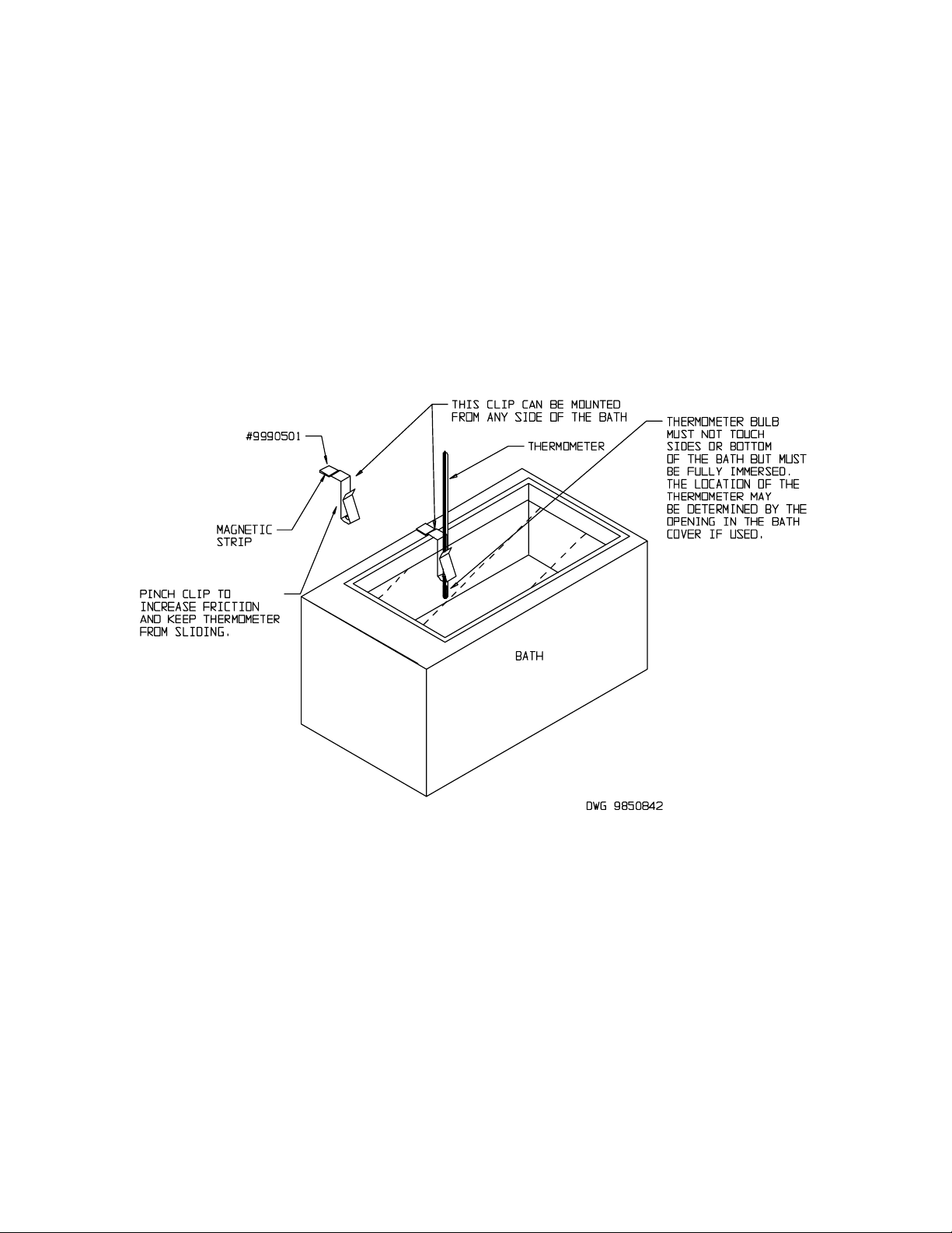
4.5 Calibrating the Control: It is recommended that the digital display be calibrated
once the unit is in its working environment. The water bath, having reached set
point and allowed to stabilize, is ready to calibrate. Place a certified reference
thermometer in the bath (a clip is provided with your accessory package. See figure
2for placement). Allow the thermometer to reach temperature where it remains
stabile for one hour. Compare the reading on the reference thermometer with the
digital display. If there is a difference, put the display into calibrate mode by
pressing the UP/DOWN arrow pads at the same time until the two outside decimal
points start to flash. When the decimal points are flashing, the display can be
changed to match the reference thermometer by pressing the UP or DOWN arrow
pads until the display reads the correct value. If the arrow pads are not pressed for
five (5) seconds the display will revert back to its original parameter. Allow the unit
to stabilize again then verify that the display matches the reference thermometer.
Sectio
n
4
Artisan Technology Group - Quality Instrumentation ... Guaranteed | (888) 88-SOURCE | www.artisantg.com

9
4.6 Set Over Temperature Safety Thermostat: As mentioned in step 4.3, the Safety
Thermostat should be initially set to its maximum position to allow the water bath to
stabilize. Once the bath is stabile at the set point, turn the Safety Thermostat
counterclockwise until the OTP light turns on. Next turn the Thermostat clockwise
just until the OTP light turns off. Then turn the Thermostat clockwise two (2) of the
smallest divisions on its scale past the point where the light went out. This will set
the Safety Thermostat at approximately 1°C above Main Temperature set point.
Figure 2
Artisan Technology Group - Quality Instrumentation ... Guaranteed | (888) 88-SOURCE | www.artisantg.com

10
MAINTENANCE
Note: Prior to any maintenance or service on this unit, disconnect service cord from
the power supply.
5.1 Cleaning: Heavy water bath use causes soiling. Clean the bath with mild soap and
water solution, rinse with clean water and wipe dry with soft cloth. Stainless steel
does not rust, but foreign materials in the tank may rust or leave rust spots. If
corrosion is seen, scrub out the stains with a mild abrasive, never steel wool. The
"PC" models, polymer coated stainless steel tanks, should only be cleaned with mild
soap - NO ABRASIVES. DO NOT USE chlorine-based bleaches or harsh
abrasives as this can damage the tank, regardless if it is stainless steel or
polymer coated. DO NOT USE spray cleaners that might leak through openings
and cracks and get on electrical parts or that may contain solvents that will harm
coatings. Failure to do this may permanently damage the unit.
WARNING: Never clean the unit with alcohol or flammable cleaners with the unit
connected to the electrical supply. Always disconnect the unit from the electrical
service when cleaning and assure all volatile or flammable cleaners are evaporated
and dry before reattaching the unit to the power supply.
Note: The heating element of this bath does not contact the tank bottom, thus will
not burn out if the tank is allowed to run dry. However, a tank going dry may strain
interior surfaces so this should not be allowed to occur.
WARNING: If tank boils dry while containing plasticware, the plastic will melt. If you
intend to use test-tube racks, remember that wire racks or plastic coated wire racks
may wear and expose metal which can cause damage. Preferably, use all plastic.
5.2 There is no maintenance required on any of the electrical components. If the unit
fails to operate as specified, please review Section 6.0 Troubleshooting, prior to
calling Customer Service.
Sectio
n
5
Artisan Technology Group - Quality Instrumentation ... Guaranteed | (888) 88-SOURCE | www.artisantg.com

11
TROUBLESHOOTING
TEMPERATURE
Temperature too high
1/ Main controller set too high-see section 4.4
2/ Main controller failed on – call Customer Service.
3/ wiring error – call Customer Service.
Display reads "HI" or "400"+
probe is unplugged, is broken or wire to sensor is broken – call
Customer Service.
Temperature spikes over set point
and then settles to set point
recalibrate – see section 4.5
Temperature too low
1/ Main controller set too low – see section 4.4
2/ bath temperature not recovered from water being added –
wait for display to stop changing.
3/ unit not recovered from power failure or being turned off –
bath will need a minimum of 2 hours to warm up and stabilize.
4/ element failure – compare current draw to data plate.
5/ Main controller failure – confirm with front panel lights that
controller is calling for heat.
6/ wiring problem – check all functions and compare wiring to
wiring schematic in section 7.0 - especially around any areas
recently worked on.
7/ loose connection – call Customer Service.
Display reads "LO"
1/ sensor is plugged in backwards – call Customer Service.
2/ if ambient temperature is lower than range of unit – compare
set points and ambient temperature to rated specifications in
section 7.0, Unit Specifications.
Unit will not heat over a temperature
that is below set point
1/ confirm that amperage and voltage match data plate.
2/ confirm that set point is set high enough.
3/ check calibration – using independent thermometer, follow
instructions in section 4.5
Unit will not heat up at all
1/ check amperage – amperage should be virtually at maximum
rated (data plate) amperage.
2/ do all controller functions work?
3/ has the fuse/circuit breaker blown?
Indicated bath temperature unstable
1/ ±0.1 may be normal, especially without the use of bath cover.
2/ is ambient room temperature radically changing – either door
opening or room airflow from heaters or air conditioning ? –
stabilize ambient conditions.
Sectio
n
6
Artisan Technology Group - Quality Instrumentation ... Guaranteed | (888) 88-SOURCE | www.artisantg.com

12
3/ calibration sensitivity – recalibrate, see section 4.5. Call
customer service if re-calibration does not resolve fluctuation.
4/ assure that the bath is at least 1/3 full.
5/ electrical noise – remove nearby sources of RFI including
motors, arcing relays or radio transmitters.
6/ bad connection on temperature sensor or faulty sensor – call
Customer Service.
Will not maintain set point
1/ assure that set point is at least 5 degrees over ambient room
temperature.
2/ see if ambient is fluctuating.
Display and Reference thermometer
don’t match
1/ calibration error – see section 4.5.
2/ temperature sensor failure – call Customer Service.
3/ controller failure – call Customer Service.
4/ allow at least two hours to stabilize.
5/ verify that reference thermometer is certified.
Can't adjust set points or calibration
1/ turn entire unit off and on to reset.
2/ if repeatedly happens, call Customer Service.
Calibrated at one temperature, but
not at another
This can be a normal condition when operating temperature
varies widely. For maximum accuracy, calibration should be
done as close to the set point temperature as possible.
MECHANICAL
Water leaking
1/ dry bath and check the tank with flashlight to see if leak is
noticeable.
2/ fill tank again and see if leak repeats and find source of leak.
Call Customer Service if continues.
Holes or rust in water bath tanks
1/ assure that clean, distilled water is used – Deionized water,
tap water and chemicals should never be used in the tank. USE
DISTILLED WATER ONLY.
2/ assure that no test sample has leaked into bath water.
3/ no metallic products should be in the tank with exception of
the polymer coated rack.
OTHER
controller on at all times - "locked-up"
1/ turn unit off and on to reset.
2/ if cannot change any condition on the front panel, call
Customer Service.
front panel displays are all off
Check for wire damage.
unit or wall fuse/circuit breaker is
blown
1/ check wall power source.
2/ compare current draw and compare to specs on data plate.
3/ see what other loads are on the wall circuit.
unit will not turn on
1/ check wall power source.
Artisan Technology Group - Quality Instrumentation ... Guaranteed | (888) 88-SOURCE | www.artisantg.com

13
2/ check fuse/circuit breaker on unit or in wall.
3/ check all wiring connections, esp. around the on/off switch.
Unit is smoking – out of box
This is not an uncommon occurrence for new units. The
elements will burn off protective coatings. Run the bath at high
temperature for one hour until smoke dissipates.
Artisan Technology Group - Quality Instrumentation ... Guaranteed | (888) 88-SOURCE | www.artisantg.com

14
PARTS LIST
Description 115V 220V
Element – 1225/1225PC, 1255/1255PC
Sm Tank 9570704 9570575
Element – 1235/1235PC, 1255/1255PC
Lg Tank 9570576 9570577
Element – 1245/1245PC 9570578 9570579
Element – 1295PC 9570743 9570744
Fuse, 6.3 AMP NA 103555
Gable Covers – 1225/1225PC,
1255/1255PC(Sm) 9750508 9750508
Gable Covers – 1235/1235PC,
1255/1255PC(Lg) 9750509 9750509
Gable Covers - 1245, 1245PC 9750510 9750510
Gable Covers - 1295PC 9750511 9750511
Microprocessor Main Temp Control 1750591 1750592
Over Temperature Safety Control 1750614 1750614
Pilot Lamp, Green 200021 200021
Pilot Lamp, Red 200020 200020
Power Cord 1800516 101990
Power Cord – European, detachable NA X1000778
Power Switch 103351 103351
Rubber Feet w/ Screws 300091 300091
Tank Gasket 103554 103554
Tanks – 1225, 1255 (Sm) 890058 890058
Tanks – 1225PC, 1255PC (Sm) 7930503 7930503
Tanks – 1235, 1255 (Lg) 890062 890062
Tanks – 1235PC, 1255PC (Lg) 7930501 7930501
Tanks – 1245 890060 890060
Tanks – 1245PC 7930502 7930502
Sectio
n
7
Artisan Technology Group - Quality Instrumentation ... Guaranteed | (888) 88-SOURCE | www.artisantg.com

15
Tanks – 1295PC 7930510 7930510
UNIT SPECIFICATIONS
Weight Shipping Net
1225, PC 21 lbs. 14 lbs
1235, PC 26.5 lbs. 18 lbs.
1245, PC 29 lbs. 25 lbs.
1255, PC 29 lbs. 32 lbs.
1295PC 34.3 lbs. 28.1 lbs.
Dimensions Exterior WxDxH
(in.)
Interior WxDxH
(in.)
1225, PC 14 x 12.5 x 9.8 11.8 x 5.8 x 6
1235, PC 14 x 19.3 x 9.5 11.8 x 12.8 x 5.8
1245, PC 14 x 26 x 10 11.5 x 19.5 x 6
1255, PC 23.5 x 19.3 x 9.3 26.5 20 x 20.5
1295PC 16 x 19 x 16 12 x 14 x 11
Capacity Liters
1225, PC 6
1235, PC 14
1245, PC 20
1255, PC 6 & 14
1295PC 30
Temperature Range Uniformity
1225, PC Amb. 5°to 100°C +0.2°C @ 37°
1235, PC Amb. 5°to 100°C +0.2°C @ 37°
1245, PC Amb. 5°to 100°C +0.2°C @ 37°
1255, PC Amb. 5°to 100°C +0.2°C @ 37°
1295PC Amb. 5°to 100°C +0.3°C @ 37°
Artisan Technology Group - Quality Instrumentation ... Guaranteed | (888) 88-SOURCE | www.artisantg.com

16
WIRE DIAGRAM
Artisan Technology Group - Quality Instrumentation ... Guaranteed | (888) 88-SOURCE | www.artisantg.com

Artisan
Technology
Group
is
an independent supplier
of
quality pre-owned equipment
Gold-standard
solutions
Extend the life
of
your
critical industrial,
commercial, and military systems
with
our
superior service and support.
We
buy
equipment
Planning to
upgrade
your current
equipment? Have surplus equipment taking
up shelf space? We'll give it a
new
home.
Learn
more!
Visit us at artisantg.com for more info
on price quotes, drivers, technical
specifications, manuals, and documentation.
Artisan Scientific
Corporation
dba
Artisan
Technology
Group
is
not
an affiliate,
representative,
or
authorized
distributor
for
any
manufacturer
listed herein.
We're here to make your life easier.
How
can
we
help you today?
(217)
352-9330
Isales@artisantg.com Iartisantg.com
This manual suits for next models
9
Table of contents
Other VWR International Laboratory Equipment manuals

VWR International
VWR International VX-2500 User manual

VWR International
VWR International VWR 10 User manual

VWR International
VWR International 20EREEVWA User manual

VWR International
VWR International DIGITRATE PRO Series User manual

VWR International
VWR International DUO SAS 360 Contact User manual

VWR International
VWR International 2400-37 User manual

VWR International
VWR International 1915A User manual

VWR International
VWR International 1915A-2 User manual

VWR International
VWR International Compact Star CS4 User manual