VWR Analogue Heavy Duty Vortex User manual

EN - English ......... 1
FR - Français ......... 13
ES - Español ......... 26
IT - Italiano ......... 39
DE - Deutsch ......... 52
PT - Português ......... 65
NL - Nederlands ......... 69
NO - Norsk ......... 73
DA - Dansk ......... 77
SV - Svenska ......... 81
FI - Suomi ......... 85
HU - Magyar ......... 89
PL - Polski ......... 93
Revision 5
11/05/17
Instruction Manual
Digital & Analogue
Heavy Duty Vortex Mixers
Microplate Vortex Mixers
European Catalogue Numbers:
Analogue Heavy Duty Vortex Mixers
Euro plug and Swiss adapter: 444-7133
UK plug: 444-7134
Digital Heavy Duty Vortex Mixers
Euro plug and Swiss adapter: 444-7130
UK plug: 444-7131
Analogue Microplate Vortex Mixers
Euro plug and Swiss adapter: 444-0986
UK plug: 444-0993
Digital Microplate Vortex Mixers
Euro plug and Swiss adapter: 444-0985
UK plug: 444-0992

1
Package contents
Heavy Duty Vortex Mixer,
Analogue or Digital
183cm detachable power cord
with Euro plug and UK plug or Swiss adapter
*
(1) cup head
(1) universal holder
(1) universal holder cover
(1) foam insert (1,5-2,0 mL microtubes, holds 38)
Instruction manual
Warranty
VWR International warrants that this product will be free from defects in material
and workmanship for a period of two (2) years from date of delivery. If a defect is
present, VWR will, at its option and cost, repair, replace, or refund the purchase price
of this product to the customer, provided it is returned during the warranty period.
This warranty does not apply if the product has been damaged by accident, abuse,
misuse, or misapplication, or from ordinary wear and tear. If the required maintenance
and inspection services are not performed according to the manuals and any local
regulations, such warranty turns invalid, except to the extent, the defect of the product
is not due to such non-performance.
Items being returned must be insured by the customer against possible damage or
loss. This warranty shall be limited to the aforementioned remedies. IT IS EXPRESSLY
AGREED THAT THIS WARRANTY WILL BE IN LIEU OF ALL WARRANTIES OF
FITNESS AND IN LIEU OF THE WARRANTY OF MERCHANTABILITY.
Compliance with local laws and regulations
The customer is responsible for applying for and obtaining the necessary regulatory
approvals or other authorizations necessary to run or use the Product in its local
environment. VWR will not be held liable for any related omission or for not obtaining
the required approval or authorization, unless any refusal is due to a defect of the
product.
table of contents
Package Contents . . . . . . . . . . . . 1
Warranty . . . . . . . . . . . . 1
Installation . . . . . . . . . . . . 2
Maintenance & Servicing . . . . . . . . . . . . 2
Environmental Conditions . . . . . . . . . . . . 2
Safety Instructions . . . . . . . . . . . . 3
Warning . . . . . . . . . . . . 3
Standards & Regulations . . . . . . . . . . . . 3
Specifications . . . . . . . . . . . . 4
Vortex Mixer Control Panels . . . . . . . . . . . . 4-5
Introduction . . . . . . . . . . . . 6
Operating Instructions . . . . . . . . . . . . 6-7
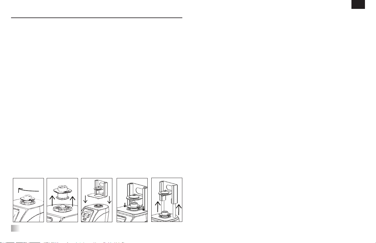
Head/Accessory Installation Instructions . . . . . . . . . . . . 8-9
Troubleshooting . . . . . . . . . . . . 10
Accessories . . . . . . . . . . . . 11-12
EC Declaration of Conformity . . . . . . . . . . . . 97-98
Legal Address of Manufacturer: VWR International bvba • Researchpark Haasrode 2020 • Geldenaakesbaan 464 • 3001 Leuven • + 32 16 385011 • http://be.vwr.com
Country of Origin: United States
EN
Microplate Vortex Mixer,
Analogue or Digital
183cm detachable power cord
with Euro plug and UK plug or
Swiss adapter
*
(1) cup head
(1) microplate holder, single
Instruction manual
OR
*
Dependent upon model

2
InstallatIon
Upon receiving the VWR Vortex Mixer, check to ensure that no damage has
occurred during shipment. It is important that any damage that occurred in
transport is detected at the time of unpacking. If you do find such damage the
carrier must be notified immediately.
After unpacking, remove the protective coverings from the feet and place the
Vortex Mixer on a level bench or table, away from explosive vapors. Ensure that
the surface on which the unit is clean and free of dust. Always place the unit on
a sturdy work surface.
The Vortex Mixer is supplied with a power cord that should be plugged into a
properly grounded outlet. If the supplied power cord does not meet your needs,
please use an approved power cord that suits local codes and electric supply.
Replacement of the plug must be made by a qualified electrician.
MaIntenance & servIcIng
The Vortex Mixer is built for long, trouble-free, dependable service. No lubrication
or other technical user maintenance is required. The unit should be given the
care normally required for any electrical appliance. Avoid wetting or unnecessary
exposure to fumes. Spills should be removed promptly. DO NOT use a cleaning
agent or solvent on the front panel which is abrasive or harmful to plastics, nor one
which is flammable. Always ensure the power is disconnected from the unit prior
to any cleaning. If the unit ever requires service, contact your VWR representative.
envIronMental condItIons
Operating Conditions: Indoor use only.
Temperature: 18 to 33°C
Humidity: 20% to 85% relative humidity, non-condensing
Altitude: 0 to 2000 M above sea level
Non-Operating Storage:
Temperature: -20 to 65°C
Humidity: 20% to 85% relative humidity, non-condensing
Installation Category II and Pollution Degree 2 in accordance with IEC 664.
equIPMent dIsPosal
This equipment must not be disposed of with unsorted waste. It is
your responsibility to correctly dispose of the equipment at
life-cycleend by handing it over to an authorized facility for
separate collection and recycling. It is also you responsibility to
decontaminate the equipment in case of biological, chemical, and/
or radiological contamination, so as to protect the persons involved
in the disposal and recycling of the equipment from health hazards.
For more information about where you can drop off your waste
of equipment, please contact your local dealer from whom you
originally purchased this equipment. By doing so, you will help to
conserve natural and environmental resources and you will ensure
that your equipment is recycled in a manner that protects human
health.
EN

3
safety InstructIons
Please read the entire instruction manual before operating the Vortex Mixer.
WARNING! DO NOT use the Vortex Mixer in a hazardous atmosphere or
with hazardous materials for which the unit was not designed. Also, the
user should be aware that the protection provided by the equipment may
be impaired if used with accessories not provided or recommended by
the manufacturer, or used in a manner not specified by the manufacturer.
Always operate unit on a level surface for best performance and
maximum safety.
DO NOT lift the Vortex Mixer by the head. All heads, including cup head,
are removable. They can pop off if lifted by them.
CAUTION! To avoid electrical shock, completely cut off power to the unit
by disconnecting the power cord from the wall outlet. Disconnect unit from
the power supply prior to maintenance and servicing.
Spills should be removed promptly. DO NOT immerse the unit for
cleaning.
DO NOT operate the unit if it shows signs of electrical or mechanical damage.
Earth Ground - Protective Conductor Terminal
Alternating Current
standards & regulatIons
VWR international hereby declares under its sole responsibility that the products
comply with the requirements of the following directives and associated standards:
Associated EU guidelines:
EMC directive 2014/30/EU
LVD directive 2014/35/EU
RoHS directive 2011/65/EU
Safety standards:
IEC 61010-1 Safety requirements for electrical equipment for
measurement, control and laboratory use. Part I:
General Requirements.
IEC 61010-2-051 Part II: Particular requirements for laboratory
equipment for mixing and stirring.
UL Std. No. 61010-1
EMC standards:
EN61326-1
FCC Part 15 Subpart B
EN

4
Heavy duty vortex MIxer sPecIfIcatIons
Overall dimensions (L x W x H): 24,1 x 16,8 x 16,5cm
Electrical (50/60 Hz): 0,13 amps | 30 watts
Fuses: 5mm x 20mm, 5 amp 250 volt quick acting
Speed range On Mode: 300-2500rpm
Touch Mode: 300-3500rpm
Orbit: 4,9mm
Duty rating: Continuous duty
Controls: Analogue: Touch/off/on - rocker switch
Speed knob: variable 1 to 10 dial marks
Digital: See page 5
Capacity: 1,1kg
Ship weight: 6,8kg
European Catalogue Numbers:
Analogue: Euro plug and Swiss adapter: 444-7133
UK plug: 444-7134
Digital: Euro plug and Swiss adapter: 444-7130
UK plug: 444-7131
MIcroPlate vortex MIxer sPecIfIcatIons
Overall dimensions (L x W x H): 26,6 x 13,7 x 11,4cm
Electrical (50/60 Hz): 0,13 amps | 30 watts
Fuses: 5mm x 20mm, 5 amp 250 volt quick acting
Speed range On Mode: 300-2500rpm
Touch Mode: 300-3500rpm
Orbit: 3,5mm
Duty rating: Continuous duty
Controls: Analogue: Touch/off/on - rocker switch
Speed knob: variable 1 to 10 dial marks
Digital: See page 5
Capacity: 2 Microplates
Ship weight: 5,4kg
European Catalogue Numbers:
Analogue: Euro plug and Swiss adapter: 444-0986
UK plug: 444-0993
Digital: Euro plug and Swiss adapter: 444-0985
UK plug: 444-0992
analogue vortex MIxer control Panel
B
A
The front panel of the Analogue Vortex Mixer contains all the switches and control
knob needed to operate the unit.
A. 3-way rocker switch: touch/off/on rocker switch starts/stops the vortexing
function.
B. Speed control: The speed control knob controls the vortexing speed. User
should turn knob clockwise until the vortexer reaches the desired speed.
EN

5
dIgItal vortex MIxer control Panel
The front panel of the Digital Vortex Mixer contains all the switches, controls and
displays needed to operate the unit.
A. 3-way rocker switch: touch/standby/on rocker switch starts/stops the
vortexing function.
B. Time display: Displays accumulated time (continuous mode) or how much
time is remaining (timed mode). The display range is from 0 to 9,999 minutes
in one (1) second increments. The display will indicate minutes and seconds
until the timer reaches 99 minutes and 59 seconds (99:59), then the display
will automatically display minutes up to 9,999.
C. Up/down arrows for set-point control.
D. Speed display: Displays the speed of the Vortex Mixer.
E. Up/down arrows for set-point control.
BD
E
C
A
EN

6
vortex MIxer IntroductIon
Your Vortex Mixer is ready for most one-handed applications. The Vortex Mixer
operates by mixing samples just prior to testing.
toucH Mode oPeratIon
NOTE: Due to the robust mechanical design of this unit, more downward force
is required to operate this unit in Touch Mode to mix single tubes as compared
to other models. Another option is to set your unit to the ON mode for mixing a
single tube.
toucH Mode oPeratIon
To ensure the stability of your vortex mixer, it is very important to start with a
smooth, clean work surface and the mixers (4) feet. If the mixer starts to “walk”,
remove the power to the unit and clean the work surface and the (4) feet with
isopropyl alcohol. Press the unit down firmly on the work surface to ensure the
feet are properly bonded.
analogue vortex MIxer oPeratIng InstructIons
1. Make sure the 3-way rocker switch is in the center, off position. Plug the power
cord into a properly grounded outlet.
2. For continuous operation, push the rocker switch to the right, on position. For
intermittent/touch operation, push the rocker switch to
the left, touch position.
3. In either case, turn the speed knob to the desired setting. In the on position,
you will see the head in motion immediately. In the touch position, the vessel
you are using must be pushed down on the head attachment to achieve motion.
To get the desired mix, vary the speed, using the speed knob, and/or vary the
angle of contact and pressure against the head.
4. When finished with either continuous or intermittent/touch operation, return
rocker switch to the center, off position.
5. The continuous, on mode is for the accessories.
6. The intermittent, touch mode is intended for short mixing times of one (1)
minute or less at full speed.
7. To completely cut off power to the unit, disconnect the power cord from the
wall outlet.
EN

7
1. Make sure the 3-way rocker switch is in the center, standby position. Plug
the power cord into a properly grounded outlet. The unit is now on and in a
standby mode.
2. For continuous operation, push the rocker switch to the right, on position. For
intermittent/touch operation, push the rocker switch to the left, touch position.
3. In either case, set the speed. In the on position, you will see the head in motion
immediately. In the touch position, the vessel you are using must be pushed
down on the head attachment to achieve motion. To get the desired mix, vary
the speed, using the speed up/down arrows, and/or vary the angle of contact
and pressure against the head.
Setting speed:
To set the speed press the up/down arrows below the speed display until you
reach the desired speed.
• Speed while running in the on position is 300 to 2500rpm
• Speed while running in the touch position is 300 to 3500rpm
Setting time:
Time operation works in both touch and on positions.
• To run in timed mode (programmed time), start by pressing the rocker
switch to the left, touch position. Press the up/down arrows below the
time display until you reach the desired time. While running unit in timed
mode, the time display will show time remaining, counting down to zero
(0:00).
• To run in continuous mode (accumulated time), reset the timer to zero
(0:00) before running. Time display will show the accumulated time and
run until you press the rocker switch to the center, standby position.
4. When finished with either continuous or intermittent/touch mode, return rocker
switch to the center, standby position.
5. The continuous, on mode is for accessories.
6. The intermittent, touch mode is intended for short mixing times of one (1)
minute or less at full speed.
7. To completely cut off power to the unit, disconnect the power cord from the
wall outlet.
Beeper Reference:
To silence the beeper operation (except for error codes), with the unit in
standby mode, remove accessories or cup head. Press and hold the head
mount. Press the time down arrow. Release the time down arrow. Release the
head mount. To restore to factory setting, repeat procedure.
dIgItal vortex MIxer oPeratIng InstructIons
EN

8
accessory InstallatIon InstructIons (all unIts)
Installing the cup head, microplate trays, universal holder or other head
attachments:
1. Move the 3-way rocker switch to the center, off/standby position.
2.
Place accessory on head mount of the unit, aligning the square on the bottom of
the accessory with the square on the top of the unit. Lower accessory
until it is
sitting on the head mount.
3. Turn the accessory counter-clockwise until it snaps into place (approximately
1/8 of a turn). Add samples to attachments after the accessory is secured onto
the Vortex Mixer. Be sure samples are secure before turning unit on.
4.
To remove an installed
accessory
, move the 3-way rocker switch to the center,
off/standby position. Turn the accessory clockwise
(approximately 1/8 of a turn)
and then lift the
accessory
straight up. Remove samples before removing the
accessories
.
• To load a microplate into the microplate tray, position the microplate against
the foam bumpers first, then push down the other side to ensure a secure fit.
To release a microplate, push it against the microplate tray’s foam bumper and
lift to remove.
• Maximum speed may vary when vortexing microplates. Speed may be
dependant on the height of the skirt on the microplate or material of the
microplate.
• Rubber vibration dampeners on the bottom of the microplate tray and universal
holder may need to be reinserted into the proper position when vortexing at
high speeds. Squeeze firmly as you maneuver it back into position.
accessory InstallatIon InstructIons (Heavy duty vortex MIxer)
Installing the vessel holders:
1. Attach the Universal Holder to the vortex mixer.
2. Place the Grip Mat in the bottom of the Universal Holder.
3. Place the flask on top of the Grip Mat, in the center of the holder.
4. Pull the center hole of the Vessel Holder over the sample container.
5. With the arrow on the Vessel Holder close to the front of the unit, the straps
should line up with the posts of the Universal Holder.
6. Push the hole on the strap over the posts on the holder. Secure the strap so
that it fits into the slot on the holder. Repeat this for the remaining two straps.
7. Be sure the sample is secure before turning unit on.
Installing the Universal Holder Cover:
1. Place the Foam Insert into the Universal Holder.
2. Lay the Universal Holder Cover on top of the foam, and align the edges.
3. Push the hole on the cover down over the post on the holder. Squeeze the
strap so that it fits into the slot on the holder, leaving the cover sitting flat on
the foam. Repeat this process for the remaining two posts.
4. To remove the accessory cover, secure the straps and pull straight up.
EN

9
Installing Single Tube Holder:
1. Move the 3-way rocker switch to the center, off/standby position.
2. Remove cup head, or any other accessory from the Vortex Mixer.
Turn the
cup head clockwise,
approximately 1/8 of a turn, (see figure 1)
and then lift
the
accessory
straight up (see figure 2). Remove samples before removing the
accessories
.
3. Align the base plate of the Single Tube Holder over the head mount of the
Vortex Mixer with the two Single Tube Holder alignment posts at the back
of the unit. Lower Single Tube Holder onto Vortex Mixer, (see figure 3) the
magnets will hold the Single Tube Holder in place. To realign this attachment,
pull up from the handle until the magnets release, check the alignment and
place again.
4. Now that the Single Tube Holder is in place, attach the cup head on the head
mount of the unit. Turn the cup head counter-clockwise until it snaps into
place, approximately 1/8 of a turn. (see figure 4)
5. Lift up on the spring loaded upper portion of the Single Tube Holder and slide
a 6,4 to 11,4cm long tube on the cup head so that the tube is aligned in the
middle (see figure 5). You are now ready to mix your sample.
1. 4.
3.2. 5.
accessory InstallatIon InstructIons (Heavy duty vortex MIxer)
EN

10
troublesHootIng (all unIts)
Error Cause of Error How to Fix
Analogue Models
Motor does not run in the touch or on mode
Digital Models
E3 Error
Analogue and Digital Models
There is no motion on the motor or the motor is not
working properly
Analogue and Digital Models
1. Turn the rocker switch to the center off/standby position
2. Check to verify the load has not been exceeded
3. Check and clear any possible obstructions of the head
mount
4. If the unit still does not work, please contact your VWR
representative
tecHnIcal servIce
For more information or technical service contact your local VWR representative or visit www.vwr.com.
Web resources: Visit VWR’s website at www.vwr.com for:
• Complete technical service contact information
• Access to VWR’s Online Catalogue, and information about accessories and related products
• Additional products information and special offers
EN

11
Microplate Holder (quad)
Designed to hold four standard microplates.
Cat. No. 444-7151
Microplate Holder (double)
Designed to hold two standard microplates.
Cat. No. 444-7138
Microplate Holder (single)
Designed to hold one microplate.
Cat. No. 444-7137
Stackable Microplate Holder Four
Designed to maximize the capacity of the Heavy Duty
Vortex Mixer to eight microplates by stacking the tray on
top of the four plate holder.
Cat. No. 444-7152
accessorIes for tHe Heavy duty vortex MIxer
Cup Head
Replacement for cup head supplied with Heavy
Duty Vortex Mixer. Designed for mixing one tube
at a time.
Cat. No. 444-7136
Single Tube Holder
Single tube hands free mixing designed to fit on
the VWR Heavy Duty Vortex Mixer. Easily attached
to the top of mixer and is magnetically secured.
Accepts tubes from 6,4-11,4cm tall. Minimum tube
diameter is 19mm.
Cat. No. 444-7150
Universal Holder
Replacement for Universal Holder supplied with
Heavy Duty Vortex Mixer to mix irregularly shaped
objects when Universal Holder Cover is in place.
Also used as a holder for the foam tube inserts.
Measures 15,5x15,0x7,6cm.
Cat. No. 444-7139
Universal Holder Cover
Replacement for Universal Holder Cover supplied
with Heavy Duty Vortex Mixer. The cover allows for
mixing irregularly shaped objects.
Cat. No. 444-7140
EN

12
accessorIes for tHe Heavy duty vortex MIxer
Small Vessel Holder
Rubber holder secures 125 and 250mL
Erlenmeyer flasks. Vessel holder also includes
a grip mat.
Cat. No. 444-7148
Foam Insert Blank
Foam insert without tube openings.
Cat. No. 444-7153
Foam Insert for 26-29mm test tubes
Foam insert holds (4) 26-29mm diameter test
tubes. Ideal for 50mL centrifuge tubes.
Cat. No. 444-7147
Large Vessel Holder
Rubber holder secures 500 and 1000mL
Erlenmeyer flasks. Vessel holder also includes
a grip mat.
Cat. No. 444-7149
Foam Insert for 22-25mm test tubes
Foam insert holds (13) 22-25mm diameter
test tubes.
Cat. No. 444-7146
Foam Insert for 1,5 to 2,0mL microtubes
Foam insert holds (38) 1,5 to 2,0mL micro-
tubes.
Cat. No. 444-7142
Foam Insert for 15-18mm test tubes
Foam insert holds (20) 15-18mm diameter
test tubes. Ideal for 15mL centrifuge tubes.
Cat. No. 444-7144
Foam Insert for 0,5mL microtubes
Foam insert holds (52) 0,5mL microtubes.
Cat. No. 444-7141
Foam Insert for 12-13mm test tubes
Foam insert holds (34) 12-13mm diameter
test tubes.
Cat. No. 444-7143
Foam Insert for 19-21mm test tubes
Foam insert holds (18) 19-21mm diameter
test tubes.
Cat. No. 444-7145
EN
Cup Head
Replacement for cup head supplied with Microplate
Vortex Mixer. Designed for mixing one tube at
a time.
Cat. No. 444-7136
Microplate Holder (single)
Replacement for Microplate Holder supplied with
Microplate Vortex Mixer. Designed to hold one
microplate.
Cat. No. 444-7137
Microplate Holder (double)
Designed to hold two standard microplates.
Cat. No. 444-7138
accessorIes for tHe MIcroPlate vortex MIxer

Révision 5
11/05/17
Manuel d’instructions
Agitateurs Vortex robustes
Agitateurs Vortex à microplaque
numériques et analogiques
Numéros de catalogues européens:
Agitateurs Vortex robustes analogiques
Fiche Euro et adaptateur suisse : 444-7133
Fiche RU : 444-7134
Agitateurs Vortex robustes numériques
Fiche Euro et adaptateur suisse : 444-7130
Fiche RU : 444-7131
Agitateurs Vortex à microplaque analogiques
Fiche Euro et adaptateur suisse : 444-0986
Fiche RU : 444-0993
Agitateurs Vortex à microplaque numériques
Fiche Euro et adaptateur suisse : 444-0985
Fiche RU : 444-0992
EN - English ......... 1
FR - Français ......... 13
ES - Español ......... 26
IT - Italiano ......... 39
DE - Deutsch ......... 52
PT - Português ......... 65
NL - Nederlands ......... 69
NO - Norsk ......... 73
DA - Dansk ......... 77
SV - Svenska ......... 81
FI - Suomi ......... 85
HU - Magyar ......... 89
PL - Polski ......... 93

14
contenu du colIs
Agitateur Vortex robuste,
analogique ou numérique
Cordon d’alimentation détachable de 183cm
avec fiche Euro et fiche RU ou adaptateur suisse*
(1) tête cupule
(1) support universel
(1) cache du support universel
(1) insert en mousse (microtubes 1,5-2,0 mL
en contenant 38)
Manuel d’utilisation
garantIe
VWR International garantit que ce produit sera exempt de défauts matériels et de
défauts de fabrication pendant une période de deux (2) ans à compter de la date de
livraison. Si une défaillance se produit, VWR réparera, remplacera ou remboursera le
prix d’achat de ce produit au client à ses frais et selon son choix, à condition qu’il soit
retourné pendant la période de garantie. Cette garantie ne s’applique pas si ce produit
a été endommagé par accident, par une utilisation abusive, une mauvaise utilisation,
ou une application inappropriée ou par une détérioration ordinaire. Si les tâches de
maintenance et d’inspections requises ne sont pas réalisés conformément aux manuels
et aux réglementations locales, cette garantie deviendrait caduque, sauf dans le cas où la
défaillance du produit n’est pas due à cette absence de maintenance ou inspection.
Les articles retournés doivent être assurés par le client contre un éventuel dommage ou
une éventuelle perte. Cette garantie se limitera aux engagements susmentionnés. IL EST
EXPRÉSSEMENT CONVENU QUE CETTE GARANTIE REMPLACERA TOUTES LES
GARANTIES D’ADAPTATION ET TOUTE GARANTIE DE QUALITÉ MARCHANDE.
Conformité avec les lois et réglementations locales
Le client est responsable de la demande et de l’obtention des autorisations réglementaires
ou autres autorisations nécessaires pour faire fonctionner ou utiliser le produit dans son
environnement local. VWR ne pourra pas être tenu pour responsable de toute omission
relative ou pour ne pas avoir obtenu l’autorisation requise, à moins qu’un refus ne soit dû
à un défaut du produit.
table des MatIeres contenu de l’eMballage
Contenu de l’emballage . . . . . . . . . . . . 14
Garantie . . . . . . . . . . . . 14
Installation . . . . . . . . . . . . 15
Maintenance et entretien . . . . . . . . . . . . 15
Conditions environnementales . . . . . . . . . . . . 15
Instructions de sécurité . . . . . . . . . . . . 16
d’alerte . . . . . . . . . . . . 16
Normes et réglementations en matière . . . . . . . . . . . . 16
Spécifications . . . . . . . . . . . . 17
Panneaux de commande de l’agitateur Vortex . . . . . . . . . . 17-18
Introduction . . . . . . . . . . . . 19
Instructions opératoires . . . . . . . . . . . . 19-20
Instructions de montage de la tête/des accessoires . . . . . . . 21-22
Dépannage . . . . . . . . . . . . 23
Accessoires . . . . . . . . . . . . 24-25
Déclaration de conformité CE . . . . . . . . . . . . 97-98
FR
Agitateur Vortex à microplaque,
analogique ou numérique
cordon d’alimentation détachable
de 183cm avec fiche Euro et fiche
RU ou adaptateur suisse*
(1) tête de la cupule
(1) support de microplaque,
manuel d’utilisation unique
ou
*En fonction du modèle

15
InstallatIon
À la réception de l’agitateur Vortex, vérifiez qu’aucun dommage n’ait été induit par
l’expédition. Il est important que tout dommage induit par le transport soit détecté
au moment du déballage. Si vous découvrez un tel dommage, vous devez en
informer immédiatement le transporteur.
Après le déballage retirez les protections des pieds et placez l’agitateur mixeur
sur un établi ou une table à niveau, loin de toutes vapeurs explosives. Assurez-
vous que la surface sur laquelle se trouve l’unité soit propre et exempte de
poussière. Placez toujours l’unité sur une surface de travail robuste.
L’agitateur Vortex est fourni avec un cordon d’alimentation qui doit être branché
dans une prise mise à la terre comme il se doit. Si le cordon d’alimentation fourni
ne répond pas à vos besoins, veuillez utiliser un cordon d’alimentation homologué
qui répond aux codes locaux et à l’alimentation électrique. Le remplacement de la
fiche doit être effectué par un électricien qualifié.
MaIntenance et entretIen
L’agitateur est conçu pour être utilisé durablement, sans problèmes et de
manière fiable. Aucune lubrification ou autre maintenance par l’utilisateur n’est
requise. L’unité doit recevoir le soin habituellement requis pour tout appareil
électrique. Évitez de la mouiller ou de l’exposer inutilement à des fumées. Les
renversements doivent être immédiatement nettoyés. N’utilisez PAS de produit
de nettoyage ni de solvant sur le panneau avant qui soit abrasif ou nocif pour les
plastiques, ni un qui soit inflammable. Assurez-vous toujours que l’alimentation
électrique soit déconnectée de l’unité avant tout nettoyage. Si l’unité nécessite un
entretien, contactez votre représentant VWR.
condItIons envIronneMentales
Conditions de fonctionnement: utilisation en intérieur uniquement.
Température : 18 à 33°C
Humidité : 20% à 85% humidité relative, sans condensation
Altitude : 0 à 2000 m au-dessus du niveau de la mer
Stockage en l’absence d’utilisation:
Température : -20 à 65°C
Humidité : 20% à 85% humidité relative, sans condensation
Catégorie d’installation II et degré de pollution 2 conformément à CEI 664.
elIMInatIon de l’equIPeMent
Cet équipement ne doit pas être éliminé avec les déchets non triés.
Vous êtes responsable de l’élimination adéquate de l’équipement
à la fin de son cycle de vie en le remettant à une installation
agréée pour une collecte et un recyclage distinct. Vous êtes
également responsable de la décontamination de l’équipement en
cas de contamination biologique, chimique et/ou radiologique, de
manière à protéger les personnes impliquées dans l’élimination et
le recyclage de l’équipement de tout risque pour leur santé. Pour
plus d’informations sur les lieux où vous pouvez déposer votre
équipement pour le jeter, veuillez contacter votre distributeur local
auquel vous aviez acheté cet équipement à l’origine. En faisant
cela, vous contribuez à préserver les ressources naturelles et
environnementales et vous assurerez que votre équipement soit
recyclé de manière à respecter la santé humaine.
FR

16
InstructIons desecurIte
Veuillez lire l’intégralité des instructions avant de faire fonctionner l’agitateur
Vortex
AVERTISSEMENT! N’utilisez PAS l’agitateur Vortex dans une atmosphère
dangereuse ou avec des matériaux dangereux pour lesquels l’unité n’a
pas été conçue. L’utilisateur doit également être conscient que la
protection apportée par l’équipement peut être diminuée s’il est utilisé
avec des accessoires non fournis ni recommandés par le fabricant, ou
utilisé d’une manière non spécifiée par le fabricant.
Faites fonctionner l’unité sur une surface à niveau pour une meilleure
performance et une sécurité maximale.
NE soulevez PAS l’agitateur Vortex par la tête. Toutes les têtes, y
compris la tête de la cupule, s’enlèvent. Elles peuvent sauter si on les
soulève en les empoignant.
PRÉCAUTION! Afin d’éviter tout choc électrique, coupez le courant
sur l’unité en débranchant le cordon d’alimentation de la prise murale.
Déconnectez l’unité de l’alimentation électrique avant toute maintenance
et tout entretien.
Les renversements doivent être rapidement nettoyés. N’immergez PAS
l’unité pour la nettoyer.
NE faites PAS fonctionner l’unité si elle montre des signes de dommage
électrique ou mécanique.
Prise de terre – Borne du conducteur de terre
Courant alternatif
norMes et regleMentatIons
VWR international déclare par la présente sous sa seule responsabilité que le
produit est conforme aux directives et normes connexes suivantes :
Directives connexes de l’UE :
Directive CEM 2014/30/UE
Directive LVD 2014/35/UE
Directive RoHS 2011/65/UE
Normes de sécurité :
CEI 61010-1 Exigences de sécurité pour les équipements électriques
destinés à la mesure, au contrôle et à une utilisation en
laboratoire. Partie I : exigences générales.
CEI 61010-2-051 Partie II : Exigences spécifiques pour les équipements de
laboratoire destinés au à l’agitation et au mélange.
UL Std. N° 61010-1
Normes CEM :
EN61326-1
FCC Partie 15 Sous-partie B
FR

17
sPécIfIcatIons agItateur vortex
Dimensions d’encombrement (L x l x H): 24,1 x 16,8 x 16,5cm
Électricité (50/60 Hz): 0,13 ampères | 30 watts
Fusibles: 5mm x 20mm, 5 amp 250 volt à action rapide
Plage de vitesse Mode On: 300-2500rpm
Mode tactile: 300-3500rpm
Orbital: 4,9mm
Facteur de service: Fonctionnement continu
Contrôles: Analogique: Tactile/off/on – interrupteur
Bouton de réglage de la vitesse : variable 1 à
10 divisions
Numérique: Voir page 18
Capacité: 1,1kg
Poids d’expédition: 6,8kg
Numéros de catalogue européen:
Analogique: Fiche Euro et adaptateur suisse: 444-7133
Fiche RU: 444-7134
Numérique: Fiche Euro et adaptateur suisse: 444-7130
Fiche RU: 444-7131
sPécIfIcatIons agItateur vortex àMIcroPlaque
Dimensions d’encombrement (L x l x H): 26,6 x 13,7 x 11,4cm
Électricité (50/60 Hz): 0,13 ampères | 30 watts
Fusibles: 5mm x 20mm, 5 amp 250 volt à action rapide
Plage de vitesse Mode On: 300-2500rpm
Mode tactile: 300-3500rpm
Orbital: 3,5mm
Facteur de service: Fonctionnement continu
Contrôles: Analogique: Tactile/off/on – interrupteur
Bouton de réglage de la vitesse : variable 1 à
10 divisions
Numérique: See page 18
Capacité: 2 Microplates
Poids d’expédition: 5,4kg
Numéros de catalogue européen:
Analogique: Fiche Euro et adaptateur suisse: 444-0986
Fiche RU: 444-0993
Numérique: Fiche Euro et adaptateur suisse: 444-0985
Fiche RU: 444-0992
Panneau de controle del’agItateur vortex analogue
B
A
Le panneau avant de l’agitateur Vortex analogique comporte tous les interrupteurs
et boutons nécessaires pour faire fonctionner l’unité.
A. Interrupteur à 3 voies: interrupteur tactile/off/on démarre/arrête le
fonctionnement du vortex.
B. Contrôle de la vitesse: le bouton de contrôle de la vitesse contrôle la
vitesse du vortex. L’utilisateur doit tourner dans le sens des aiguilles d’une
montre jusqu’à ce que le vortex atteigne la vitesse souhaitée.
FR

18
Panneau de controle de l’agItateur vortex
Le panneau avant de l’agitateur Vortex numérique contient tous les interrupteurs,
contrôles et affichages requis pour faire fonctionner l’unité.
A. Interrupteur à 3 voies: interrupteur tactile/pause/on démarrant/arrêtant la
fonction du vortex.
B. Affichage de la durée: affiche le temps accumulé (en mode continu)
ou le temps restant (mode minuté). La plage d’affichage va de 0 à 9,999
minutes en intervalles d’une (1) seconde. L’affichage indiquera les minutes et les
secondes jusqu’à ce que le minuteur atteigne 99 minutes et 59 secondes
(99:59), puis l’affichage affichera automatiquement les minutes jusqu’à 9,999.
C. Flèches vers le haut/le bas pour contrôler la valeur de réglage.
D. Affichage de la vitesse: affiche la vitesse de l’agitateur Vortex.
E. Flèches vers le haut/bas pour contrôler la valeur de réglage.
BD
E
C
A
FR

19
PrésentatIon de l’agItateur
Votre agitateur Vortex est prêt pour la plupart des applications à une main.
L’agitateur Vortex fonctionne en agitant des échantillons juste avant le test.
fonctIonneMent enMode tactIle
REMARQUE: à cause du design robuste de cette unité, plus de force
descendante est requise pour faire fonctionner cette unité en mode tactile afin de
mélanger des tubes uniques par rapport à d’autres modèles. Une autre option est
de paramétrer votre unité en mode ON pour mélanger un seul tube.
fonctIonneMent enMode tactIle
Afin de garantir la stabilité de votre agitateur vortex, il est très important de
commencer avec une surface de travail lisse et propre et les (4) pieds de
l’agitateur. Si l’agitateur commence à « se déplacer », débranchez l’alimentation
sur l’unité et nettoyez la surface de travail et les (4) pieds avec de l’alcool
isopropylique. Appuyez fortement sur l’unité sur la surface de travail afin de vous
assurer que les pieds soient bien fixés.
InstructIons defonctIonneMent agItateur vortex analogIque
1. Assurez-vous que l’interrupteur à trois voies se trouve au centre, en position
off (arrêt). Branchez le cordon d’alimentation dans une prise de courant
correctement mise à la terre.
2. Pour un fonctionnement continu, appuyez à la droite de l’interrupteur, en
position on (marche). Pour une utilisation intermittente/tactile, appuyez
à gauche de l’interrupteur, en position « touch » (tactile).
3. Dans tous les cas, tournez le bouton de réglage de la vitesse sur la valeur
souhaitée. En position On vous verrez que la tête se mettra immédiatement
en mouvement. En position « touch », vous devez appuyer sur le récipient
que vous utilisez sur la fixation de la tête afin que le mouvement débute.
Pour obtenir l’agitation souhaitée, ajustez la vitesse en utilisant le bouton de
réglage de la vitesse et/ou modifiez l’angle de contact et la pression sur la tête.
4. Lorsque vous avez terminé avec le fonctionnement intermittent/tactile,
remettez l’interrupteur au centre, en position off.
5. Le mode on, continu, est destiné aux accessoires.
6. Le mode intermittent, tactile est destiné aux courtes durées d’agitation de
moins d’une (1) minute ou moins à plein régime.
7. Pour couper complétement l’alimentation sur l’unité, débranchez le cordon
d’alimentation de la prise murale.
FR
This manual suits for next models
3
Table of contents
Other VWR Mixer manuals