VWR VWR B2 Series User manual

User Manual
VWR B2 SERIES BALANCES
Rev B2-05

- 2 -
TABLE OF CONTENTS
1.General Information....................................................................................4
1.1. INTENDED USE......................................................................................4
1.2. INAPPROPRIATE USE ..............................................................................4
1.3. WARRANTY............................................................................................4
2. UNPACKING AND INSTALLATION ................................................................4
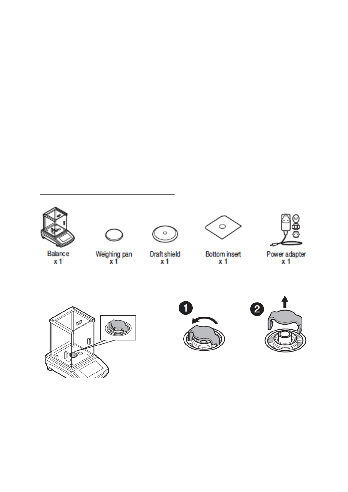
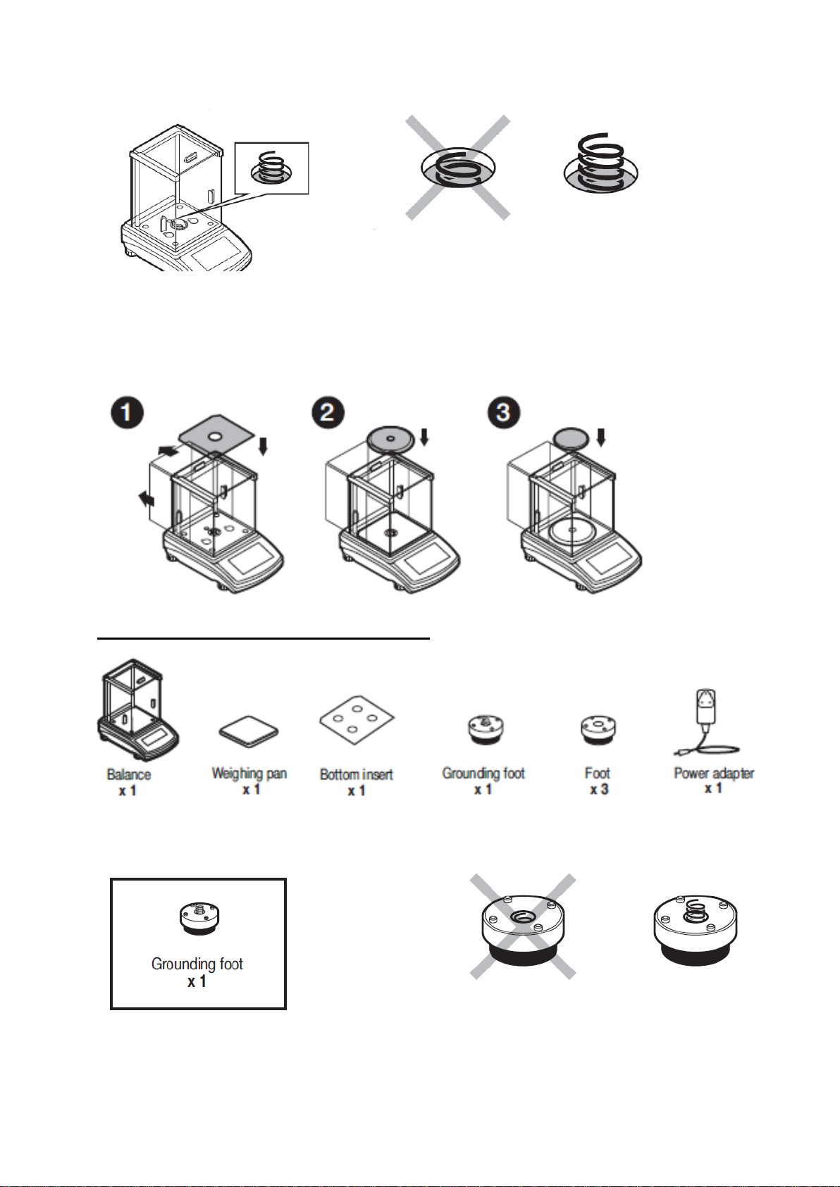
2.1. STANDARD DELIVERY COMPONETS LIST...................................................4
2.2. UNPACKING...........................................................................................4
2.3. PLACE OF USE AND ASSEMBLY ................................................................5
2.4. BALANCE ASSEMBLY...............................................................................5
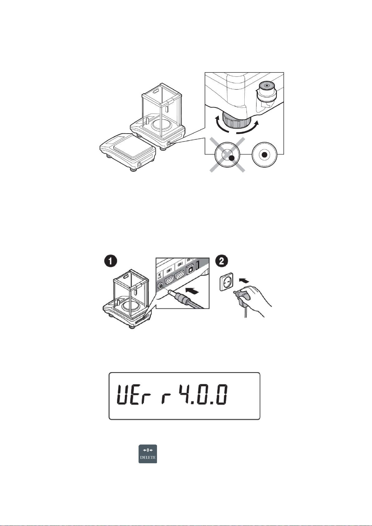
2.5. BALANCE LEVELING................................................................................8
2.6. POWERING THE DEVICE..........................................................................8
3. KEYBOARD – BUTTON FUNCTIONS ..............................................................9
4. START-UP..................................................................................................10
4.1. TEMPERATURE STABILIZATION PERIOD.................................................. 10
4.2. USER MENU......................................................................................... 10
5. BALANCE OPERATION – GENERAL INFORMATION.....................................12
5.1. BALANCE ZEROING .............................................................................. 12
5.2. BALANCE TARING................................................................................. 12
5.2.1. MANUAL TARE DETERMINATION.............................................................12
5.2.2. DELETING TARE ...................................................................................12
5.3. UNITS................................................................................................. 13
5.4. TEMPORARY MEASURING UNIT .............................................................. 13
5.5. UNITS ACCESSIBILITY.......................................................................... 13
5.6. START UNIT SELECTION ....................................................................... 13
5.7. CUSTOM UNIT...................................................................................... 14
6. WORKING MODES- GENERAL INFORMATION.............................................14
6.1. RUNNING WORKING MODE.................................................................... 15
6.2. WORKING MODE ACCESSIBILITY ........................................................... 15
6.3. WORKING MODE PROFILE ..................................................................... 15
6.4. WORKING MODE SETTINGS- READING ................................................... 16
6.4.1. FILTER LEVEL SETTING.........................................................................16
6.4.2. VALUE RELEASE...................................................................................17
6.4.3. AUTOZERO..........................................................................................17
6.4.4. LAST DIGIT DISPLAY ............................................................................18
6.4.5. BALANCE AMBIENT CONDITIONS ...........................................................18
6.5. WORKING MODE SETTINGS- AUTOTARE ................................................. 18
6.6. WORKING MODE SETTINGS- PRINT MODE .............................................. 19
6.7. WORKING MODE SETTINGS- INFORMATION............................................ 21
6.8. WORKING MODE SETTINGS- Non-Standard INFORMATION........................ 21
6.9. WORKING MODE SETTINGS- F shortcut keys........................................... 22
7. CALIBRATION............................................................................................23
7.1. CALIBRATION MENU SETTINGS.............................................................. 23
7.2. EXTERNAL CALIBRATION....................................................................... 23
7.2.1. EXTERNAL CALIBRATION.......................................................................23
7.2.2. USER CALIBRATION..............................................................................23
7.3. CALIBRATION REPORT PRINTOUT........................................................... 24

- 3 -
8. WEIGHING ................................................................................................24
8.1. UNDER-PAN WEIGHING ........................................................................ 25
9. PARTS COUNTING .....................................................................................26
9.1. SETTING REFERENCE MASS: MASS DETERMINATION FOR THE SAMPLE OF
KNOWN QUANTITY....................................................................................... 26
9.2. SETTING REFERENCE MASS: ENTERING MASS VALUE............................... 27
10. DEVIATIONS .............................................................................................28
10.1.SETTING THE REFERENCE MASS: WEIGHING REFERENCE SAMPLE............. 28
10.2.SETTING THE REFERENCE MASS: ENTERING THE MASS VALUE.................. 28
11. DENSITY OF SOLIDS..................................................................................29
12. DENSITY OF LIQUIDS................................................................................31
13. ANIMAL WEIGHING...................................................................................32
13.1.RUNNING THE PROCESS MANUALLY ....................................................... 33
13.2.RUNNING THE PROCESS AUTOMATICALLY............................................... 34
14. MISCELLANEOUS PARAMETERS.................................................................34
15. DETERMINIG PRINTOUT CONTENT............................................................36
15.1.CALIBRATION REPORT.......................................................................... 36
15.2.HEADER, FOOTER, GLP PRINTOUTS........................................................ 37
15.3.NON-STANDARD PRINTOUTS................................................................. 38
15.4.VARIABLES.......................................................................................... 39
16. COMMUNICATION......................................................................................40
16.1.RS 232 PORT SETTING (COM)................................................................ 40
17. DEVICES....................................................................................................40
17.1.COMPUTER.......................................................................................... 40
17.2.PRINTER ............................................................................................. 41
18. COOPERATION WITH DEVICES..................................................................42
18.1.TRANSFERRED DATA FORMAT................................................................ 43
18.2.FORMAT OF DATA SENT ON PRESSING PRINT BUTTON ............................. 43
19. COMMUNICATION PROTOCOL....................................................................44
19.1.LIST OF COMMANDS............................................................................. 44
20. APPENDIX .................................................................................................53
20.1.DIMENSIONS....................................................................................... 53
20.2.CONNECTORS...................................................................................... 53
20.3.CONNECTION CABLES - DIAGRAMS........................................................ 54
20.4.MAINTENANCE ACTIVITIES.................................................................... 54
21. ERROR MESSAGES .....................................................................................56

- 4 -
1.GENERAL INFORMATION
1.1. INTENDED USE
B2 series balances are designed to provide accurate measurement of weighed loads, performed
under laboratory conditions. It is intended for application as a non-automatic weighing instrument
only, i.e. the material to be weighed is manually and carefully placed in the center of the weighing
pan. Weighing result should be read only after stable reading has been obtained.
1.2. INAPPROPRIATE USE
Do not use the balance for a dynamic weighing. Even if small quantities of weighed material are
added or removed from the weighing pan of the instrument, the reading should be taken only after
stabilization of the measurement results. Do not place any magnetic materials on the weighing pan,
as this can cause damage to the measuring system of the instrument.
Be sure to avoid impact shock and overloading the balance in excess of the prescribed maximum
measuring range (max capacity), minus any possible tare weight that has been applied.
Never use the balance in an environment where explosion is possible. This balance has not been
adjusted for operation in explosive areas.
There must not be any modification made to the balance.
1.3. WARRANTY
Warranty is invalid for the following:
•non-observation of the guidelines of this user manual,
•use of the balance other than specified in this manual,
•alteration to or opening of the device,
•overloading of the measuring instrument.
2.UNPACKING AND INSTALLATION
2.1. STANDARD DELIVERY COMPONETS LIST
•Balance and components shown in Section 2.4 depending on balance model
•Warranty Card
•User Manual
2.2. UNPACKING
To unpack the system, follow the diagram below-

- 5 -
2.3. PLACE OF USE AND ASSEMBLY
•The balance should be stored and used in locations free of vibrations and shakes, free of
air movement and dust.
•Ambient air temperature should not exceed the range of: +10 °C ÷ +40 °C.
•Ambient relative humidity should not exceed 80%.
•During balance operation, ambient temperature in the weighing room should not change
rapidly.
•The balance should be located on a stable wall console desk or a stable working table
which is not affected by vibrations and distant from heat sources.
•Take special precaution when weighing magnetic objects, as part of the balance is a
strong magnet. Should such loads be weighed, use under-pan weighing option, which
removes the weighed load from area influenced by the balance’s magnet. The hook for
under-pan weighing is installed in balance’s base.
•Keep all package element should your device be transported in the future. Remember that
only original packaging can be used for shipping purposes. Prior to packing, uncouple any
cables, remove any separable components (weighing pan, shields, inserts). Pack the
device components into an original packaging. The original packaging protects the
equipment against potential damage during transportation.
2.4. BALANCE ASSEMBLY
Model: VWR-64B2, VWR-124B2, VWR-214B2
Components-
Installation-
1)Remove the transport lock– gently press the transport lock and turn it accordingly to
<OPEN>, keep the transport lock should your balance be transported in the future.

- 6 -
2)Check grounding spring to insure it is in the appropriate location. Make sure that the grounding
spring juts slightly out of the hole.
3)Install components following diagram below:
i. Bottom insert
ii. Centering ring [embossment side up]
iii. Weighing pan
Model: VWR-203B2, VWR-403B2, VWR-503B2
Components:
Installation:
1)Check that the grounding spring is in the correct location, the spring juts slightly out of the hole.

- 7 -
2)Install components following the diagram below:
i. Bottom Insert
ii. Rubber feet (grounding foot can be in any location on the balance)
iii. Weighing pan
Model: VWR-4002B2, VWR-5002B2
Components:
Installation:
1)Install components following the diagram below:
i. Draft Shield
ii. Weighing pan

- 8 -
2.5. BALANCE LEVELING
It is necessary to level the balance prior to plugging it in. To level the balance, turn its feet until
the air bubble is in the center position.
The balance should firmly rest on a surface, each of the feet must be supported.
2.6. POWERING THE DEVICE
Balance can be connected to the mains only with a power adapter that comes standard with the
particular model. Nominal power supply of the power adapter (specified on the power adapter data
plate) should be compatible to the power from the mains.
Plug the balance to the mains – connect the power adapter to the socket, next connect its connector
to port located at the back of the balance housing.
Test of the display unit takes place right after connecting the balance to the power, all the elements
and pictograms are backlit for a short time. Next, the name and the program number appears (please
note, software version number may be different than what appears below)
The indication then goes to ZERO (displayed reading unit depends on the balance). If the indication
is different than zero, please press button.

- 9 -
3.KEYBOARD – BUTTON FUNCTIONS
Press to switch the balance ON/OFF. If switched off, balance
components other than the display are powered, and balance is in
stand-by mode.
Press to access data stored in a database: user, product, tare.
Press to enter directly the active working mode settings.
Press to select working mode.
F5 button of the computer keyboard.
Press to change measuring units.
PRINT/ENTER button
Press to send measurement to a printer or a computer (PRINT).
Press to confirm selected parameter value or function (ENTER).
Press to Zero the balance
Press to Tare the balance
Press to start adjustment / calibration process immediately.
Press to enter the main menu of a balance.
Press to operate balance menu or change parameter value.

- 10 -
4.START-UP
When plugged to mains, the balance displays program name and number, next it proceeds to the
weighing mode.
4.1. TEMPERATURE STABILIZATION PERIOD
Before start of measuring processes, it is necessary to wait until the balance reaches thermal
stabilization.
For balances that were stored in much lower temperatures before plugging to mains (e.g. during
winter period), thermal stabilization period shall take at least 4 hours for balances with d=0.001g and
d=0.01g balances, and 8 hours for balances with d=0.1mg balances. During the thermal stabilization,
the indications on the display panel can change.
It is recommended that ambient temperature changes at place of use were insignificant (slow to
change).
4.2. USER MENU
Menu is divided into 9 basic function groups. Each group has an individual name starting with
a capital letter, P.
P1 CALIBRATION
P1.1
EXT. CALIB.
|
[external adjustment]
P1.2
USER CALIBRATION
|
[user adjustment]
P2 WORKING MODES
P2.1
ACCESSIBILITY
|
[settings for the accessibility of individual modes
while working with the balance]
P2.2
WEIGHING
|
[setting for the function weighing]
P2.3
COUNTING PCS
|
[settings for the function counting pieces]
P2.4
DEVIATIONS
|
[settings for the function deviat
ions % against
the mass of the standard]
P2.5
DENS. OF SOLIDS
|
[settings for determining density of solids]
P2.6
DENS OF LIQUIDS
|
[settings for determining density of liquids]
P2.7
ANIMAL WEIGHING
|
[settings for the function animal weighing]
P3 COMMUNICATION
P3.1
COM1
|
[transmission parameters port COM 1]
P4 DEVICES
P4.1
COMPUTER
|
[PC connection port]
P4.2
PRINTER
|
[printer connection port]

- 11 -
P5 PRINTOUT
P5.1
CAL. REPORT
|
[contents of the adjustment report]
P5.2
HEADER
|
[contents of the header printout]
P5.3
GLP PRNT.
|
[contents of the weighing result prnt.]
P5.4
FOOTER
|
[contents of the footer printout]
P5.5
NSD.PRN.1
|
[project of non-standard printout 1]
P5.6
NSD.PRN.2
|
[project of non-standard printout 2]
P5.7
NSD.PRN.3
|
[project of non-standard printout 3]
P5.8
NSD.PRN.4
|
[project of non-standard printout 4]
P5.9
VARIABLE1
|
[project of variable 1]
P5.10
VARIABLE2
|
[project of variable 2]
P5.11
SEPARATOR DOT
|
[choose . or , to separate digit readout]
P6 OTHER
P6.1
LANGUAGE
|
[menu language]
P6.2
KEY SOUND
|
[key sound]
P6.3
BACKLIGHT
|
[display backlight level]
P6.4
STAND-BY MODE
|
[backlight turn-off time interval]
P6.5
AUTO SWITCH OFF
|
[display turn-off time interval]
P6.6
DATE
|
[date settings]
P6.7
TIME
|
[time settings]
P6.8
DATE FORM.
|
[date format]
P6.9
TIME FORM.
|
[time format]
P6.10
RESTORE USER DEFAULTS
|
[return to factory default settings]
P7 INFO
P7.1
BALANCE ID
|
[balance serial number]
P7.2
SCALE TYPE
|
P7.3
SOFT.VER.
|
P7.4
ID PROD
|
P7.5
TEMP.
|
P7.6
SETUP PRNT.
|
[print balance setup]
P8 UNITS
P8.1
ACCESSIBILITY
|
[declaration of units to be available for balance
operation]
P8.2
START UNIT
|
[selection of a start unit, unit active on balance start-
up]
P8.3
USER UNIT U1
|
[parameter defining user’s unit 1]
P8.4
USER UNIT U2
|
[parameter defining user’s unit 2]
CAUTION!
Balance memory modifications will be saved upon abandoning the menu (on return to weighing).
Press ESC button several times.

- 12 -
5.BALANCE OPERATION – GENERAL INFORMATION
5.1. BALANCE ZEROING
Zeroing is a function allowing to zero the mass on the indication. To perform this function, press
button. Mass indication of zero value shall be displayed together with precise zero and
stability markers .
The zeroing process is an equivalent for determining new zero point, recognized by the balance as
precise zero. Zeroing is possible only for stable status of display indication.
!CAUTION
Zeroing the display indication is possible only within ±2% range of instrument’s maximum
capacity. If the zeroed value is above ±2% of the maximum capacity, then the balance
indicates a respective -Err2- error message.
5.2. BALANCE TARING
Taring is a function allowing to determine net weight of a measured object. To determine the net
weight of the object, place object’s container (packaging) on the weighing pan, and on stabilization of
measurement result press key. The display indicates mass equaling zero and symbols: Net
and . On taking off the weighed load and its packaging from the weighing pan, the display
indicates sum of total tared mass with a minus sign.
The balance allows the user tare value to a database-stored product. Using this option, the software
automatically uploads data on tare value for a particular product upon its selection from the database.
!CAUTION
Taring negative values is impossible. On taring negative values the balance responds with
an error message,- Err3 -. In such case, zero balance indication and repeat taring
procedure.
5.2.1. MANUAL TARE DETERMINATION
This option allows for the setting of a tare value through a manual input of the value.
Procedure:
•Press quick access key F2, to which <ENTER TARE> option has been assigned.
•Wait for a respective window to open.
•Use the arrow buttons to enter the tare value and press button,
•The balance returns to the weighing mode, and the display indicates entered tare
value with minus “–" sign.
5.2.2. DELETING TARE
Entered tare value can be deleted by pressing button on the overlay or by entering tare
value of 0.000g (see description above)

- 13 -
5.3. UNITS
UNITS parameter group enables the user to change availability of mass units (the change can be
performed in-course of balance operation), and to define two custom units, thus positively effecting
comfort and speed of operation. It is possible to change unit to other than unit [g] during weighing
process or during operation of other modes. Working modes Parts Counting and Percent Weighing
are exceptions.
5.4. TEMPORARY MEASURING UNIT
Function enables selecting a measuring unit which is to be indicated next to mass reading during the
operation. The set measuring unit will be in use from the moment of its activation until its change or
switching the balance off and on.
Each pressing of the button results with change of the measuring unit.
Options:
•[g], [mg], [kg], [ct], [lb], [oz], [ozt], [dwt], [tlh], [tls], [tlt], [tlc], [mom], [gr], [ti], [N]
5.5. UNITS ACCESSIBILITY
By pressing button , the user may declare units to be available for selection of temporary unit.
Units with parameter value set to <YES> are available for selection in specified operating modes.
Procedure:
5.6. START UNIT SELECTION
Upon selection of start unit, the balance activates with the specified unit for these modes where
change of the unit is possible.
Ability of selecting a given unit depends on the balance status, i.e. if the balance is verified or not.
Procedure:

- 14 -
5.7. CUSTOM UNIT
You can declare two custom units. The custom unit is a result of indication multiplied by a specified
coefficient.
The units are displayed as [u1] – user unit 1, and [u2] – user unit 2.
Procedure:
6.WORKING MODES- GENERAL INFORMATION
The balance features the following working modes:
Weighing
Means of operation: weight of a load is determined through an indirect measurement. A
balanc
e measures gravitational force which attracts the load. An obtained result is
processed to a digital format and displayed in a form of measurement result.
Parts Counting
Means of operation: based on a determined mass of a single part it is possible to count
another part, if the mass of the single part is determined with sufficient accuracy, and that
the following parts are equal in mass.
Deviations % (Percent Weighing)
Means of operation: control of percent ratio of a sample in relation to a standard
(reference). Obtained data provides percent ratio on how test sample differs from the
accepted standard (reference).
Density of solids
Means of operation: based on Archimedes principle, a balance determines density of
solids. The mode requires an optional density determination kit.
Density of liquids
Means of operation: based on Archimedes principle, a balance determines density of
liquids. The mode requires an optional density determination kit.
Animal Weighing
Means of operation: mass measurement takes place with application of filters dampening
animal moves on a weighing pan, thus enabling obtaining a correct measurement result.

- 15 -
6.1. RUNNING WORKING MODE
In order to run a particular mode press button, and select the mode from thelist.
Procedure:
CAUTION!
Upon restart, the balance is launched with the most recently operated working mode. For settings
of this function read later sections of this user manual.
6.2. WORKING MODE ACCESSIBILITY
User’s have the availability to declare which working modes are to be accessible. You can deactivate
working that are not used in course of balance operation, to do it, change the accessibility value to
<NO> for a particular parameter.
Procedure:
6.3. WORKING MODE PROFILE
To simplify balance operation, there are 4 profiles in the software. The profiles are selected and
saved so that the weighings for respective requirements and conditions are optimized. Profile
settings apply to settings for specific working mode.
These are the following profiles:
•User - the basic profile for which filter settings are selected in a way enabling fast and precise
weighing
•Fast - profile enabling weighing of any mass regardless of the working mode. When running
the balance for the first time, this profile is started automatically. For this profile the parameters
are selected in a way enabling obtaining the measurement result as fast as it is possible
•Fast dosing – the profile is dedicated for fast dosing.
•Precision – the profile is dedicated for precise dosing of any mass regardless of the working
mode. For this profile the weighing process takes the most time, but the result is the most
accurate and precise

- 16 -
Caution: You can modify all settings of User profile. Settings of other profiles (Fast, Fast dosing and
Precision) can be modified only to a limited extend.
Name of currently selected profile is displayed in the bottom line. The profile can be selected
individually for working mode. The balance saves the last used profile in each working mode (with
your modifications) and starts operation with that profile selected.
Procedure:
•Press button, utilize navigation keys to reach reach <Profil> and press button
•Utilize navigtion keys to reach proper profile, select profile by pressing button
•The balance returns to main screen and operates in accordance with set profile.
6.4. WORKING MODE SETTINGS- READING
The software allows setup of operating parameters (filters, value release, and autozero function, last
digit, and other setting) seperately for each working mode. Only for User profile can you modify all
settings. For other profiles (Fast, Fast dosing, Precision) filter and value release parameters are
default and cannot be modified.
It enables customizing the instrument and utilizing its properties depending on your needs and
expectations, or on specific requirements for selected working mode (e/g/ DOSING); as a result the
device operation is quick and easy.
6.4.1. FILTER LEVEL SETTING
Filter level setting (function unavailable for the following profiles: Fast, Fast dosing,
Precision)
Filter settings calibration depends on the working environment. For the best possible conditions
the filter can work in a very fast mode (V.FAST value for Filter parameter); however, if the
conditions are poor (shakes, drafts), the filter should be set to slow or very slow option (SLOW or
V. SLOW value for Filter parameter). The effectiveness of the filter is different throughout the
weighing range. The filter works slower when “approaching” the weighed mass, it works more
intensively for weighed mass within the set range of the filter (the parameter for setting filter range
is accessible only from the service menu – the user does not have any access to it).
Depending on the filter, the weighing time is shorter (V.FAST and FAST) or longer (SLOW and V.
SLOW).

- 17 -
6.4.2. VALUE RELEASE
Value release setting (function unavailable for the following profiles: Fast, Fast dosing,
Precision)
Since ambient conditions at a workplace vary, it is necessary to determine the value release
parameter that are best for your working environment, parameter options are: <FAST.+REL.>,
<FAST> or <RELIABLE>. Depending on the selected option, weighing time is either shorter or
longer.
Procedure:
6.4.3. AUTOZERO
The balance features an autozero function (Auto). This function automatically controls and
corrects the zero reading. When Autozero is enabled, it compares balance readings at declared
time interval e.g. 1s, if weighing pan is unloaded and display indication is close to zero. If results
vary less than declared AUTOZERO range e.g. one division, balance zeroes automatically,
marker of stable measurement result , and precise zero marker are displayed.
If AUTOZERO function is enabled, then each weighing process starts from precise zero point.
There are, however, some instances when this function can be a disturbing factor for the
measuring process; e.g. very slow placing of a load on the weighing pan (load adding). Here,
zero reading correction can also correct the actual reading of loaded mass.
Procedure:

- 18 -
6.4.4. LAST DIGIT DISPLAY
Function enables displaying the last digit of decimal place for a weighing result. There are three
available options:
•<ALWAYS> all digits visible
•<NEVER> last digit is not displayed
•<WHEN STB> last digit is displayed only for a stable weighing result
Procedure:
6.4.5. BALANCE AMBIENT CONDITIONS
Parameter relating to ambient and environmental conditions in which the balance operates.
There are two options: <STABLE> and <UNSTABLE>.
•Selecting <STABLE> mode makes the balance work much faster, i.e. weighing takes
much less time than for <UNSTABLE> mode.
•If the ambient conditions are unstable it is recommended to use UNSTABLE mode. By
default, the parameter is set to <STABLE> option.
Procedure:
6.5. WORKING MODE SETTINGS- AUTOTARE
Autotare is used for quick determination of net weight for loads with different tare values, wherein
they are measured one after another.
When the function is active (<AUTOTARE> parameter set to <YES> option), the operating process
takes the following steps.
Procedure:
•Make sure that the weighing pan is empty and press button responsible forzeroing.
•Put product packaging on a weighing pan.
•After measurement stabilization, automatic taring of the packaging mass takes place (Net
marker then appears in the upper part of thedisplay).
•Place product to be weighed into the packaging.
•The display shows net weight of theproduct.
•Remove the product together with thepackaging from the weigh pan.

- 19 -
•The balance removes the tare value (packaging weight recorded during the first step of the
operating process) after the gross weight value (set in <AUTO THRES> parameter) has been
exceeded.
•Place packaging of the next product on the weighing pan, automatic taring of the packaging
weight proceeds after measurement stabilization (Net marker appears in the top section of the
display);
•Place next product that is to bepacked.
For correct operation of the balance with AUTOTARE function, it is necessary to adjust the threshold
value.
<AUTO THRES> parameter is connected with the following functions:
•automatic tare
•automatic operation
No automatic taring takes place as long as the gross weight value stays within the range set in
<AUTO THRES> parameter.
6.6. WORKING MODE SETTINGS- PRINT MODE
Function designed to enable print mode setting, it activates key.
Print mode options:
•<WHEN STAB>, for this option stable measurement result, along with the settings for
parameter <GLP PRINTOUT>, is sent to the printer port. On pressing key, when the
result is not stable (no marker on a display), the balance software sends the measurement
result to the port after reaching stability for the measurement.
•<EACH>, for this option every single pressing of button results with sending the
measurement indication to the printer port along with the settings for <GLP PRINTOUT>
parameter. Every single indication is sent (stable and unstable). For unstable indication <?>
character appears at the beginning of the printing frame. This function applies to non-
verified balances exclusively.

- 20 -
•<AUTO> - select this option to enable automatic printing of measurements. If this option has
been selected, remember to set <AUTO THRES> parameter to suit your needs.
•<AUTO+INT.> select this option to start automatic printout and record of indications in
Weighings database and Alibi database, carried out in a cyclic manner in a specified time
interval. The interval is set in minutes, in parameter P2.2.3.3 <AUTO INT.>. Interval range is 1-
9999 min.
For automatic operation with interval it is necessary to specify interval value in [min].
CAUTION!
Each result is printed and recorded (stable and unstable). Automatic operation with interval starts at
the moment of switching the function on and it lasts until it is switched off. On switching the function
of auto print with interval, PRINT button becomes inoperative (no indication is printed when pressed).
Automatic operation procedure:
•Press button to zero the balance (marker of stable measurement and zero marker
are shown on a display).
•Deposit load, the balance sends the first stable measurement to the printer port.
•Remove the load from the pan.
•The next measurement is possible when the indication is lower than the set value of <AUTO
THRES.> parameter (next measurement does not require zero value).
For automatic operation adjust the threshold value.
This manual suits for next models
3
Table of contents
Other VWR Scale manuals
Popular Scale manuals by other brands

Eldom
Eldom GWO190 instruction manual

Intelligent Weighing Technology
Intelligent Weighing Technology HS Series Operation manual

Beurer
Beurer GS 44 High Tech Instructions for use

SR Instruments
SR Instruments SR Scales SR 735i Operating and service manual

Scarlett
Scarlett SC-BS33ED12 instruction manual

U-Line
U-Line OHAUS CS H-2715 manual