TABLE OF CONTENTS
1. INTENDEDUSE...................................................................................................................................................5
2. PRECAUTIONS...................................................................................................................................................5
2.1.
Maintenance ..................................................................................................................................................5
2.2.
Accumulator / batterypack.............................................................................................................................5
2.3.
Operation in a strong electrostaticfield..........................................................................................................6
2.4.
Maintenanceactivities....................................................................................................................................6
3.
WARRANTY CONDITIONS ................................................................................................................................7
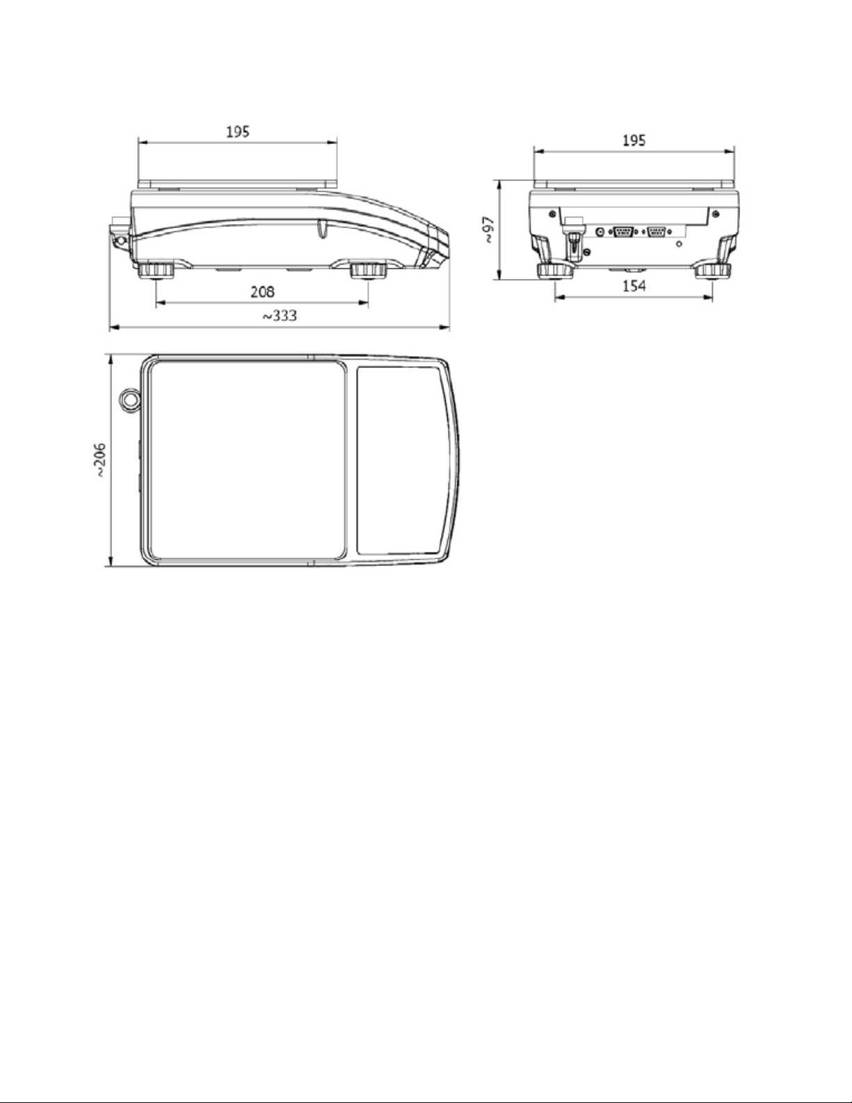
4.
MAIN DIMENSIONS ............................................................................................................................................8
5.
UNPACKING ANDASSEMBLY..........................................................................................................................9
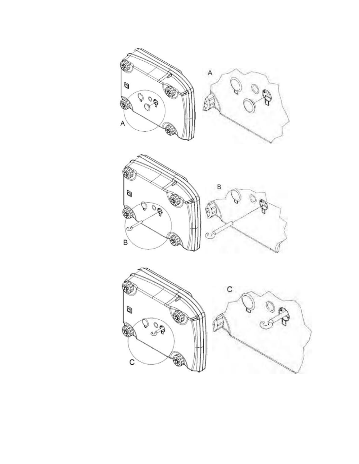
6.
UNDER-PANWEIGHING ....................................................................................................................................9
7.
GETTING STARTED......................................................................................................................................... 11
8.
BALANCELEVELING...................................................................................................................................... 11
9.
KEYPAD............................................................................................................................................................ 11
10.
KEYS’ FUNCTIONS ................................................................................................................................... 12
11.
INSCRIPTIONS ON THEDISPLAY ........................................................................................................... 12
12.
USER MENU............................................................................................................................................... 13
12.1.
Submenus........................................................................................................................................... 13
12.2.
Browsing usermenu ........................................................................................................................... 14
12.2.1.
Keypad................................................................................................................................................ 14
12.2.2.
Return to the weighing mode.............................................................................................................. 15
13.
WEIGHING ................................................................................................................................................. 15
13.1.
Taring.................................................................................................................................................. 16
13.2.
Inscribing tarevalue............................................................................................................................ 17
13.3.
Zeroing................................................................................................................................................ 17
13.4.
Selection of basic weightunit.............................................................................................................. 18
13.5.
Temporarily selectedunit.................................................................................................................... 19
14.
MAIN PARAMETERS................................................................................................................................. 20
14.1.
Setting a filtering level......................................................................................................................... 20
14.2.
Median filter ........................................................................................................................................ 21
14.3.
Autozerofunction ................................................................................................................................ 21
14.4.
Tare function....................................................................................................................................... 22
15.
RS 232 PARAMETERS.............................................................................................................................. 24
15.1.
Printouttype........................................................................................................................................ 24
15.2.
Minimal massthreshold ...................................................................................................................... 25
15.3 Baud Rate.................................................................................................................................................. 26
15.4 Serial transmissionparameters ................................................................................................................. 27
16.
OTHER PARAMETERS.............................................................................................................................. 28
16.1.
Backlight function................................................................................................................................ 28
16.1.1 Backlight for supplying frommains......................................................................................................... 28
16.1.2.
Backlight for supplying from batteries ................................................................................................ 29
16.2.
“Beep” signal – after pressing akey.................................................................................................... 29
16.3.
Automatic switch-off............................................................................................................................ 30
16.4.
Battery voltage levelcheck.................................................................................................................. 31
16.4.1.
Checking thebatteries ........................................................................................................................ 31
16.4.2.
Battery dischargepictogram................................................................................................................ 32
16.4.3.
Accumulator chargingoption .............................................................................................................. 32
17.
OPERATION MODES................................................................................................................................ 33
17.1.
Setting accessibility of operationmodes............................................................................................. 33
17.2.
Selecting quantity of operationmodes................................................................................................ 34
17.3.
Counting pieces of the samemass..................................................................................................... 34
17.4. +/- control referring to the inscribed standard mass Procedure:.............................................................. 37
17.5.
Control of % deviation referring to the inscribed standard mass......................................................... 38
17.5.1.
Standard mass determined by its weighing........................................................................................ 39