WABASH COMMUNICATIONS MBS-1P User manual

MBS-1P
Installation Guide
APRIL 2003
Heavy Duty Trailer ABS
by Wabash National
®

Notes, Cautions, and Warnings
This manual contains Notes, Cautions, and Warnings in addition to the
assembly instructions.
Notes: Provide additional comments to help with installation and set up.
Cautions: Provide notification of situations that can cause damage to
machinery and tools.
Warnings: Provide alerts to situations that can cause personal injury
or death.
Please take the time to read and understand this manual before
beginning assembly.
CAREFULLY FOLLOW THE SAFETY AND OPERATING
INSTRUCTIONS IN THIS MANUAL.
Due to a policy of continuous product improvement, we reserve the right
to make changes at any time, without notice, in prices, materials, colors,
specifications, equipment, models, and availability. Some photos and
drawings in this manual contain optional equipment. Since some
information may have been updated since the time of printing, please
check with your Wabash dealer for complete details.
© 2003 Wabash Technology Corp. All rights reserved. No portion of these
materials may be reproduced, stored, or transmitted without prior written
approval of Wabash National.
Wabash is an equal opportunity employer. M/F/V/H

®
i
MBS-1P Installation
322UX040
Top of ECM
+
+
+
MBS-1
MBS-1P
MBS-2
No Marking
or
One of the Following:
Numbers "1", "2", "3", "4" or "5"
in this Area.
Wheel Speed Sensor
Cable Location
Wheel Speed Sensor
Wire Goes Into
Backing Plate
Wheel Speed Sensor
Wire Goes Into
Backing Plate
Wheel Speed Sensor
Wire Goes Into
Axle Tube
Wheel Speed Sensor
Wire Location
Wheel Speed Sensor
Wire Location
Top of ECM
The Letter "P"
in this Area.
The Letter "P"
in this Area.
Top of ECM
MBS Identification
Before service or diagnostics is performed on a Wabash MBS unit, the system design must be
verified. Do not rely on labels or verbal descriptions to identify the MBS system. Refer to the
illustration below and compare the marking in the lower right-hand corner of the ECM with the
location(s) of the wheel speed sensor wire or cable on the trailer’s axle(s). Make sure to properly
identify the Wabash MBS; flash codes and system components are different for each system.

®
ii
MBS-1P Installation
Contents
Wabash MBS-1P ABS Introduction . . . . . . . . . . . . . . . . . . . . . . . . . . . . . . .1
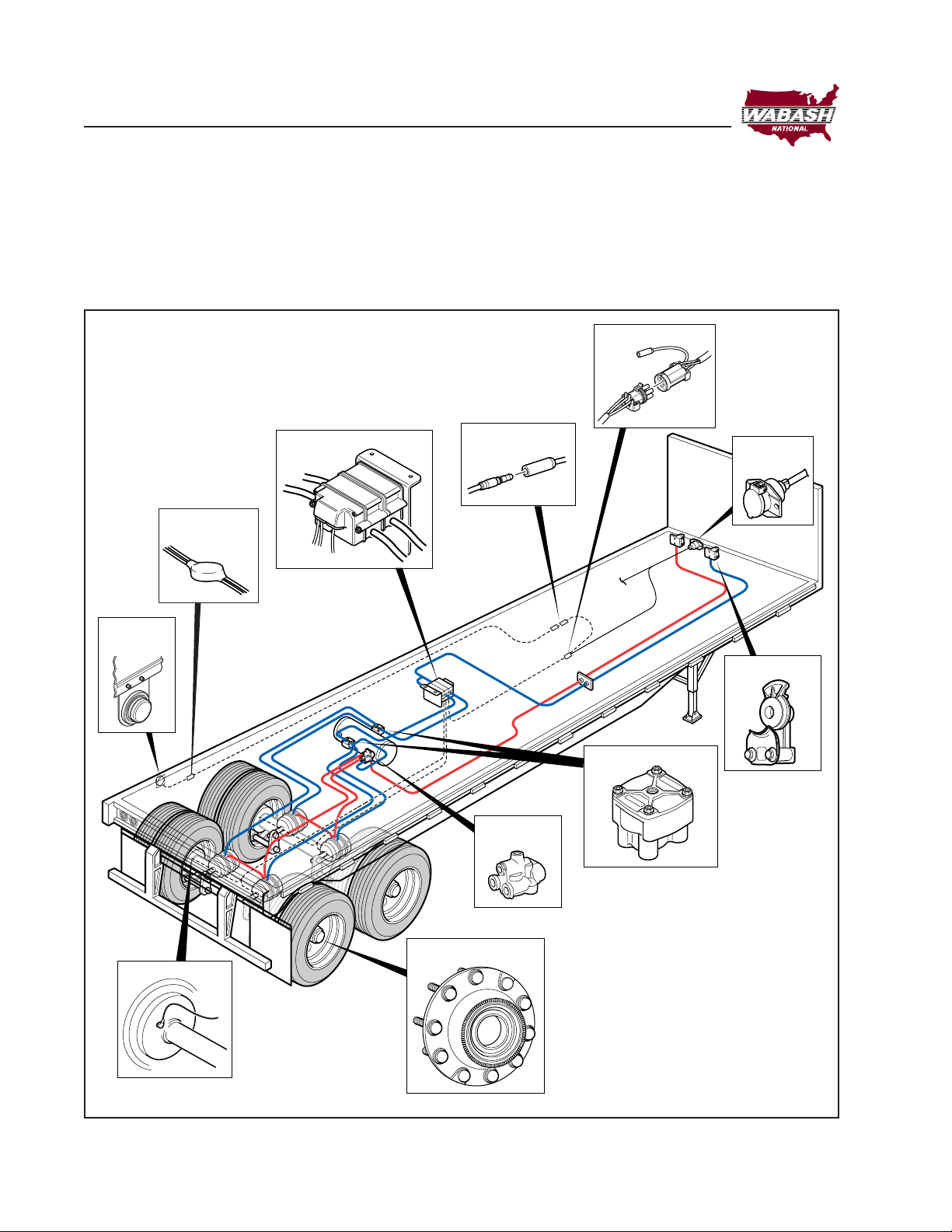
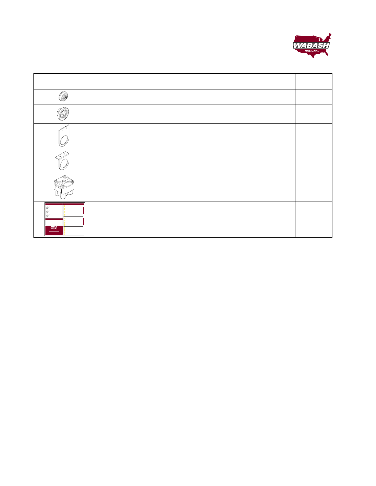
MBS-1P System Components . . . . . . . . . . . . . . . . . . . . . . . . . . . . . . . . . . .2
General Air Brake Requirements . . . . . . . . . . . . . . . . . . . . . . . . . . . . . . . . .5
ABS . . . . . . . . . . . . . . . . . . . . . . . . . . . . . . . . . . . . . . . . . . . . . . . . . . . . . . . . .6
Key Dates . . . . . . . . . . . . . . . . . . . . . . . . . . . . . . . . . . . . . . . . . . . . . . . . .6
ABS Design Requirements . . . . . . . . . . . . . . . . . . . . . . . . . . . . . . . . . . . .6
Type of ABS Required for Trailers . . . . . . . . . . . . . . . . . . . . . . . . . . . . . . .6
Power Requirements for ABS . . . . . . . . . . . . . . . . . . . . . . . . . . . . . . . . . .7
ABS Malfunction Lamp . . . . . . . . . . . . . . . . . . . . . . . . . . . . . . . . . . . . . . . 7
Location . . . . . . . . . . . . . . . . . . . . . . . . . . . . . . . . . . . . . . . . . . . . . . . . . .7
Color and Labeling . . . . . . . . . . . . . . . . . . . . . . . . . . . . . . . . . . . . . . . . . .8
Intensity and Photometric Requirements . . . . . . . . . . . . . . . . . . . . . . . . .8
Power Line Carrier (PLC) . . . . . . . . . . . . . . . . . . . . . . . . . . . . . . . . . . . . . 8
Applications . . . . . . . . . . . . . . . . . . . . . . . . . . . . . . . . . . . . . . . . . . . . . . . . . .9
Electrical System . . . . . . . . . . . . . . . . . . . . . . . . . . . . . . . . . . . . . . . . . . . .12
Pneumatic System . . . . . . . . . . . . . . . . . . . . . . . . . . . . . . . . . . . . . . . . . . .13
Installation of Electrical System . . . . . . . . . . . . . . . . . . . . . . . . . . . . . . . .14
Power and Sensor Cables . . . . . . . . . . . . . . . . . . . . . . . . . . . . . . . . . . .14
MBS-1P Cable Options . . . . . . . . . . . . . . . . . . . . . . . . . . . . . . . . . . . . . 14
Circuit Requirements . . . . . . . . . . . . . . . . . . . . . . . . . . . . . . . . . . . . . . .16
Malfunction Lamp Diagnostic Switch . . . . . . . . . . . . . . . . . . . . . . . . . . .16
Pneumatic System . . . . . . . . . . . . . . . . . . . . . . . . . . . . . . . . . . . . . . . . . . .17
MBS-1P Location and Mounting . . . . . . . . . . . . . . . . . . . . . . . . . . . . . . .17
Plumbing Instructions . . . . . . . . . . . . . . . . . . . . . . . . . . . . . . . . . . . . . . .18
Relay Valve . . . . . . . . . . . . . . . . . . . . . . . . . . . . . . . . . . . . . . . . . . . . . . .20
Sensors . . . . . . . . . . . . . . . . . . . . . . . . . . . . . . . . . . . . . . . . . . . . . . . . .20
Hub Installation . . . . . . . . . . . . . . . . . . . . . . . . . . . . . . . . . . . . . . . . . . . . . .22
Initial System Checkout . . . . . . . . . . . . . . . . . . . . . . . . . . . . . . . . . . . . . . .24
ABS System Diagnostics . . . . . . . . . . . . . . . . . . . . . . . . . . . . . . . . . . . . . .25
Initial System Checkout . . . . . . . . . . . . . . . . . . . . . . . . . . . . . . . . . . . . .25
Pneumatic Diagnostics . . . . . . . . . . . . . . . . . . . . . . . . . . . . . . . . . . . . . . 25
Electrical Diagnostics . . . . . . . . . . . . . . . . . . . . . . . . . . . . . . . . . . . . . . .25
Troubleshooting The System . . . . . . . . . . . . . . . . . . . . . . . . . . . . . . . . . . .26
Entering the Flash Code Diagnostic Mode . . . . . . . . . . . . . . . . . . . . . . .27
Suitable Light Tester . . . . . . . . . . . . . . . . . . . . . . . . . . . . . . . . . . . . . . . .27
Current Faults . . . . . . . . . . . . . . . . . . . . . . . . . . . . . . . . . . . . . . . . . . . . .28
Stored Faults . . . . . . . . . . . . . . . . . . . . . . . . . . . . . . . . . . . . . . . . . . . . .30
Clearing Stored Faults . . . . . . . . . . . . . . . . . . . . . . . . . . . . . . . . . . . . . .32
Malfunction Lamp Diagnostic Switch . . . . . . . . . . . . . . . . . . . . . . . . . . .34
Sensor Signal Faults (Trace) . . . . . . . . . . . . . . . . . . . . . . . . . . . . . . . . .36
Malfunction Lamp Failure . . . . . . . . . . . . . . . . . . . . . . . . . . . . . . . . . . . .38
MBS-1P Electrical Schematic . . . . . . . . . . . . . . . . . . . . . . . . . . . . . . . . . . .39
Glossary . . . . . . . . . . . . . . . . . . . . . . . . . . . . . . . . . . . . . . . . . . . . . . . . . . . .40

®
1
MBS-1P Installation
Wabash MBS-1P ABS Introduction
The Wabash MBS-1P ABS enhances the original MBS-1 system by adding
Power Line Carrier (PLC) and expanding the number of configuration options.
The system can be configured with either two or four sensors and either one
or two pneumatic control modules. The Antilock Control Module (ACM) is
separate from the service brake relay valve, eliminating costly repairs
associated with relay valve failure. The choice of service brake relay can be
separate from choice of ABS. This is also an advantage when troubleshooting
the brake system.

®
2
MBS-1P Installation
Figure 1, Wabash MBS-1P Antilock Brake System
MBS-1P System Components
Wabash’s MBS-1P system includes unique ABS components as well as
interfacing with standard trailer components (see Figure 1). Refer to
Figures 2 and 3 for part number and description of Wabash parts.
322UX023
R-12 Relay Valve
Power Cable
Malfunction
Lamp
Spring Brake
Control Valve
PCM/ECM
Gladhand
Malfunction Lamp
Connector
Diagnostic
Switch
J560
Connector
ABS Hub
Sensor

®
3
MBS-1P Installation
Figure 2, MBS-1P System Components
Component Item Description Qty.
Req'd
Supplied
in Kit
322UX031
10800313 2S-1M w/168" Power Cable 1 yes
10800314 2S-1M w/30" Power Cable
10800358 2S-2M w/168" Power Cable
10800357 2S-2M w/30" Power Cable
10800353 4S-1M w/168" Power Cable
10800362 4S-1M w/30" Power Cable
10800349 4S-2M Side-by-Side w/168" Power Cable
10800361 4S-2M Side-by-Side w/30" Power Cable
10800360 4S-2M Axle-by-Axle w/168" Power Cable
10800359 4S-2M Axle-by-Axle w/30" Power Cable
14401359 ABS Wiring Harness 1 yes
14401744 ABS Malfunction Lamp 1 yes
Harness w/Diagnostic Switch
12S00475 MBS-1P Mounting Bracket 1 yes
(optional)
BLT00650 Bolt 1/4-20 x 3-1/2" Grade 8 (1M Sys.) 2 yes
BLT00732 Bolt 1/4-20 x 5-1/2" Grade 8 (2M Sys.) 2 yes
NUT00007 Nut 1/4-20 Nylon Insert Locknut 2
WSH00010 Washer 1/4" SAE Flat 2
10800225 Bosch ABS Sensor 2 yes
10800126 Wabco ABS Sensor
10800068 Midland ABS Sensor
10800226 Bosch ABS Sensor Clip 2 yes
10800009 Wabco ABS Sensor Clip
10800069 MidlandABS Sensor Clip

®
4
MBS-1P Installation
Component Item Description Quantity
Required
14200428 Yellow ABS Malfunction Lamp 1 yes
14200018 Closed Back MalfunctionLamp Grommet 1 yes
14A00049 Straight Malfunction Lamp — no
Mounting Bracket
14A00050 90°Malfunction Lamp Mounting Bracket — no
12900570 Relay Valve 1 yes
25000972 MBS-1P Flash Code Decal 1 yes
Supplied
in Kit
322UX024
TO READ CURRENT FAULTS
PRESSTWO TIMES
(HOLD 2ND PRESS FOR
THREE SECONDS)
TO READ STORED FAULT
PRESSTHREE TIMES
(HOLD 3RD PRESS FOR
THREE SECONDS)
1) SYSTEMSWITH 1 PCM DO NOT UTILIZE FLASH
CODE 11
2) SYSTEMSWITH 2 SENSORS DO NOT UTILIZE
FLASH CODES 7-10 AND SENSORS MAY BE
LOCATED ON EITHER FRONT OR REAR AXLE
TO CLEAR STORED FAULTS
PRESS FOUR TIMES
(HOLD 4TH PRESS FOR
THREE SECONDS)
(ALLOWONE SECOND BETWEEN PRESSES)
X 2
FLASHTHREE TIMES
CURBSIDE SENSOR SIGNAL
(FRONT CURBSIDE ON 4 SENSOR SYSTEMS)
X 3
FLASH FOUR TIMES
CURBSIDE SENSOR CONNECTION
(FRONT CURBSIDE ON 4 SENSOR SYSTEMS)
X 4
FLASH FIVE TIMES
ROADSIDE SENSOR SIGNAL
(FRONT ROADSIDEON 4 SENSOR SYSTEMS)
X 5
FLASH SIX TIMES
ROADSIDE SENSOR CONNECTION
(FRONT ROADSIDEON 4 SENSOR SYSTEMS
X 6
FLASH SEVEN TIMES
CURBSIDE REAR SENSOR SIGNAL
X 7
FLASH EIGHT TIMES
CURBSIDE REAR SENSOR CONNECTION
X 8
FLASH NINE TIMES
ROADSIDE REAR SENSOR SIGNAL
X 9
X 3
X 4
FLASHTEN TIMES
ROADSIDE REAR SENSOR CONNECTION
X 10
FLASH ELEVEN TIMES
SECONDARYPCM FAULT
X 11
FLASHTWELVE TIMES
PRIMARYPCM FAULT
X 12
FLASH FOURTEEN TIMES
LOWVOLTAGETO ABS
X 14
FLASH FIFTEEN TIMES
ELECTRONIC CONTROL MODULE
X 15
FLASH CODE QUICK REFERENCE
DIAGNOSTIC SWITCH INPUT
NOTE
2S AND 4S SYSTEMS 4SSYSTEMS ONLY
DECAL PARTNUMBER: WN#25000972
PLC-4 TRUCKS COMPATIBLE
MBS-1P
TRAILERANTI-LOCK BRAKE SYSTEM
APRODUCT OF WABASHNATIONAL
®
Figure 3, MBS-1P System Components

®
5
MBS-1P Installation
General Air Brake Requirements
FMVSS-121 identifies minimum requirements for air brake systems on
commercial vehicles built in the U.S. (Requirements in Canada are covered
under CMVSS-121 and are virtually identical.) These regulations cover
requirements for new construction. Once put into operation, proper use and
maintenance is covered under standards such as:
•FMCSR 393 – Covers required equipment
•FMCSR 396 – Covers inspection and repair.
The requirements for spring brake performance and operation, reservoir size
and air timing have not been changed with the introduction of ABS. Because
the addition of ABS components can have an affect on air brake timing, it is
important to verify acceptable performance on new ABS installations. The
maximum application and release times permitted under FMVSS-121 are
shown in Figure 4.
Figure 4, Air Timing Requirements
Measured at Brake Chamber 50 CI Reservoir Brake Chamber 50 CI Reservoir
Initial Condition 0 PSIG 0 PSIG 95 PSIG 5 PSIG
Towing Trailer 500 500 1000 1000
Converter Dolly 550 550 1100 1000
Single Trailer 600 N/A 1200 N/A
Apply Time (mSec)
From pedal
movement to
reach 60 PSIG
From pedal
movement to
reach 60 PSIG
From pedal
movement to
reach 5 PSIG
From pedal
movement to
reach 5 PSIG
Release Time (mSec)
322UX032

®
6
MBS-1P Installation
ABS
Key Dates
March 1, 1997 Tractors must be equipped to provide full time power
to trailers.
March 1, 1998 Newly manufactured trailers must be equipped with ABS.
Some special use cases are exempt. (Refer to FMVSS-121
for specific details.)
April 1, 2000 ABS required on newly manufactured Canadian Vehicles.
March 1, 2001 Trailer malfunction lamp is required in the tractor cab.
March 1, 2008 Trailer mounted malfunction lamp no longer required.
ABS Design Requirements
Under FMVSS-1221, an approved ABS must automatically control the degree
of rotational wheel slip during braking by:
1. Sensing the rate of angular rotation of the wheels.
2. Transmitting signals regarding the rate of wheel angular rotation to one or
more controlling devices which interpret those signals and generate
responsive controlling output signals.
3. Transmitting those controlling signals to one or more modulators which
adjust brake actuating forces in response to those signals.
Type of ABS Required for Trailers
ABS control is required on trailers as follows:
•Full Trailers – Direct ABS Control is required on at least one front and
one rear axle.
•Semi Trailers and Dollies – Direct ABS Control is required on at least
one axle.
Direct Control refers to an axle that is equipped with wheel speed sensors
and is controlled by a modulator valve or valves in response to the wheel
speed sensor signals. If this valve(s) also controls the brakes of another
axle(s) that does not have sensors, the axle(s) is referred to as an indirectly
controlled axle(s).

®
7
MBS-1P Installation
Power Requirements for ABS
For trailers built after March 1 of 1998, the trailer wiring system must provide
two sources of power for the antilock system.
1. Full-time power (when ignition is on) must be provided by the tractor. This
full-time power source may be shared with other trailer circuits. The SAE
J560 Blue (AUX) circuit is commonly used as the full-time power source.
In other cases, a separate ISO 3731 connector is provided.
2. Brake light power. This input provides a source of backup power for cases
where an older tractor (without full-time power) is used to tow a trailer or
in case of a failure of the permanent power source.
Industry standards (TMC RP-137 and SAE2247) require that the tractor
provide at least 10 amps at 12 volts at the trailer end of the SAE J560 or ISO
cable on all ABS power circuits. Suppliers of Trailer ABS have agreed to
provide for proper antilock brake operation down to a minimum of 8.5 volts.
The ABS malfunction lamp will light if voltages drop too low to maintain reliable
solenoid operation.
Wabash National antilock systems operate at voltages down to 7.0 volts.
Current requirements are approximately 330 milliamps per control unit and
1.25 amps per PCM.
ABS Malfunction Lamp
Rules for the location, color, labeling, intensity and photometrics for external
ABS malfunction lamps have been established by the National Highway
Transportation Safety Administration (NHTSA). These requirements are
effective as of March 1, 1998.
Location
The lamp mounting location shall be near the left side rear of the trailer, no
closer than 150 mm (5.9 inches) and not more than 600 mm (23.6 inches)
from the rear red side marker indicator lamp. On a converter dolly, the lamp
mounting location shall be on a permanent structure of the dolly at least
375 mm (14 inches) above the road surface. After March 1st, 2001 a second
ABS malfunction lamp must be located in the cab.

®
8
MBS-1P Installation
Color and Labeling
The malfunction indicator lamp must be yellow in color and identified with
the letters “ABS” to distinguish the lamp from other yellow side markers.
The letters may be on the lens, on the lens housing, or on the trailer itself,
near the lamp.
Intensity and Photometric Requirements
The external ABS malfunction indicator lamp must conform to SAE-J592
JUN92. Trailers shall use a combination clearance/side marker lamp marked
with a “PC” or “P2”. These lamps offer a widely diffused beam pattern
throughout a full 180-degree left and right range.
Power Line Carrier (PLC)
In order to meet the (March 2001) requirement to provide a tractor-mounted
trailer ABS malfunction lamp, the industry has adopted power line carrier
(PLC) technology. The use of a power-line-carrier permits transmission of
data between tractors and trailers without adding wires or connectors.
Data is transmitted as a series of high frequency chirps that appear on the
ABS full-time power line (the blue wire). The chirps vary in frequency
between 100K Hz and 400K Hz. The PLC signals are transmitted between
trailer ABS control units and tractor ABS control units. The tractor ABS unit
has an additional output signal that controls the cab-mounted trailer ABS
malfunction lamp.
The cab-mounted trailer ABS malfunction lamp:
•Lights to indicate a bulb check at start-up
•Remains lit at start-up if a fault code is set
•Will turn OFF after two seconds if the trailer is disconnected
•Lights during vehicle operation to indicate a fault has occurred.
In order for PLC to function, tractors and trailers must both be equipped with
PLC versions of ABS. All Wabash National MBS-1P systems manufactured
after March 1, 2001 are PLC capable.

®
9
MBS-1P Installation
Applications
The performance of the Wabash MBS-1P ABS depends upon proper
installation of all components. Trailer suspension, axle configuration, and other
brake components will affect the level of ABS performance.
The “Sensed” and the “Controlled” axles must be considered prior to
installation of the MBS-1P. Wabash recommends the following guideline for
typical MBS-1P installations.
When locating the sensors on a 2S system, choose the axle that locks up first
during hard braking. Typically, the front axle tends to lock up first on spring
suspension trailer applications. On air suspension systems, the axles tend to
lock up at the same time, so it is recommended that the rear axle be sensed
because of the added stability.

®
10
MBS-1P Installation
Figure 5, Wabash MBS-1P Application Chart
MBS-1P
CONTROLLED AXLES
CONTROLLED AXLE
SENSED AXLE
MBS-1P
MBS-1P
MBS-1P
SENSED AXLE
CONTROLLED AXLE
SENSED
AXLE
CONTROLLED AXLES
SENSED
AXLE
CONTROLLED AXLES
CONTROLLED AXLE
SENSED AXLE
SENSED AXLE
2S-2M
CONTROLLED AXLES
CONTROLLED AXLE
SENSED AXLE
SENSED AXLE
CONTROLLED AXLE
SENSED AXLE
One valve
each side
One valve
each side
One valve
each side
One valve
each side CONTROLLED AXLES
SENSED AXLE
322UX036
SPRING SUSPENSION AIR SUSPENSION
2S-1M
MBS-1P
MBS-1P
MBS-1P
MBS-1P
MBS-1P
MBS-1P
MBS-1P
CONTROLLED AXLE
SENSED
AXLE
Air Suspended
Dollies Not Commonly
Available
MBS-1P
CONTROLLED AXLES
SENSED
AXLE
Air Suspended
Dollies Not Commonly
Available
#10800313 #10800313
#10800313
#10800313
#10800314 #10800314
#10800314 #10800314
#10800358 #10800358
#10800358 #10800358

®
11
MBS-1P Installation
322UX035
SPRING SUSPENSION AIR SUSPENSION
CONTROLLED AXLES
One valve
each side
SENSED AXLES
SENSED AXLES
SENSED AXLES
CONTROLLED AXLES
SENSED AXLES
CONTROLLED AXLES
SENSED AXLES
CONTROLLED AXLES
CONTROLLED AXLES
SENSED AXLES
CONTROLLED AXLES
SENSED AXLES
CONTROLLED AXLES
SENSED AXLES
4S-1M
4S-2M Side Control
4S-2M Axle Control
One valve
each side
One valve
each side
One valve
each side
CONTROLLED AXLES
CONTROLLED
AXLE
SENSED AXLES
CONTROLLED AXLES
CONTROLLED
AXLE
MBS-1P
MBS-1P
MBS-1P
MBS-1P
MBS-1P
MBS-1P
MBS-1P
MBS-1P
CONTROLLED AXLES
SENSED AXLES
Air Suspended
Dollies Not Commonly
Available
# 10800353
Contact customer service for assistance when installing
ABS on units with axle spreads that exceed 11 feet.
Contact customer service for assistance when installing
ABS on units with axle spreads that exceed 11 feet.
# 10800353
# 10800362 # 10800362
# 10800349 # 10800349
# 10800361 # 10800361
# 108003360 # 108003360
MBS-1P MBS-1P
Figure 6, Wabash MBS-1P Application Chart

®
12
MBS-1P Installation
Electrical System
The Antilock Control Module (ACM) consists of an Electronic Control Module
(ECM) and a Pneumatic Control Module (PCM) combined as one unit.
However, they are individually field replaceable. The wheel sensor, malfunction
lamp, and power harnesses are connected to the ECM.
Figure 7, Typical Electrical System Layout
322UX028
J560
Connector
Power Cable
ABS
Malfunction
Lamp
PCM/ECM
Malfunction Lamp
Connector
Diagnostic
Switch
Sensor

®
13
MBS-1P Installation
Pneumatic System
The PCM contains the pneumatic solenoids that physically control pressure in
the service line to the relay valve. The 3/8" service line enters and exits the
PCM through integrated quick connect fittings. The PCM also incorporates a
quick exhaust valve that minimizes delays during brake release and helps
purge contaminants that may enter the service control line.
Figure 8, Typical Pneumatic Layout for a 2M System
322UX027
R-12 Relay Valve
Spring Brake
Control Valve
PCM/ECM
Gladhand

®
14
MBS-1P Installation
Installation of Electrical System
Power and Sensor Cables
One power cable, and two or four sensor connector cables are integrated into
the MBS-1P. The power cable runs to the Weather Pack 5-way connector on
the trailer. The sensor cables terminate in molded two-pin (industry standard)
connectors.
MBS-1P Cable Options
The MBS-1P can be configured with either a long or short power cable. Refer
to the system component charts on page 3 and 4 for specific system and part
number information.
The short power cable is typically used with fixed bogies.
The long power cable is typically used with sliding bogies. Route the power
cable with the slider hoses to the trailer frame.
NOTE: The long cable can also be used on fixed bogies if required.
MBS-1P with short power cable (WNC part number 10800262).

®
15
MBS-1P Installation
Figure 9, MBS-1P Components and Connectors
322UX025
ECM
Power
Harness
PCM
Sensor
Harnesses

®
16
MBS-1P Installation
Circuit Requirements
The solenoid valves used in the Wabash MBS products allow higher airflow
and require less voltage and current than most trailer ABS systems. For a
nominal 12-volt supply, current consumption is about 1.25 amperes maximum
during ABS activity. Satisfactory operation is available down to 7 volts.
The MBS-1P minimizes trailer issues caused by inadequate voltage (typically
found in 3-trailer units).
Malfunction Lamp Diagnostic Switch
NOTE: The malfunction lamp bulb must be incandescent. Always replace
the bulb with another incandescent bulb of the same value.
A diagnostic switch is located near the ABS malfunction lamp. A malfunction
lamp harness incorporating this switch is included in the MBS-1P kit.
NOTE: While this feature is desirable, it is not essential. Diagnostic flash
codes can also be activated from the tractor cab via the ignition switch.
Figure 10, ABS Malfunction Lamp Installation
322UX026
Malfunction
Lamp Pigtail
Malfunction Lamp
Power Wire
Malfunction Lamp
Diagnostic Switch
Malfunction Lamp
(Must be incandescent)
MBS-1P
Flash Code
Decal
Malfunction Lamp
Mounting Bracket
Trailer Wall
Power
Cable
Connector
Malfunction Lamp
Ground Wire
TOREAD CURRENT FAULTS
PRESSTWO TIMES
(HOLD2ND PRESS FOR
THREESECONDS)
TOREAD STORED FAULT
PRESSTHREE TIMES
(HOLD3RD PRESS FOR
THREESECONDS)
1)SYSTEMSWITH1PCMDONOTUTILIZEFLASH
CODE11
2)SYSTEMSWITH2SENSORSDONOTUTILIZE
FLASHCODES7-10ANDSENSORSMAYBE
LOCATEDONEITHERFRONTORREARAXLE
TOCLEAR STORED FAU LTS
PRESSFOUR TIMES
(HOLD4TH PRESS FOR
THREESECONDS)
(ALLOWONESECONDBETWEENPRESSES)
X2
FLASHTHREETIMES
CURBSIDESENSORSIGNAL
(FRONTCURBSIDEON4SENSORSYSTEMS)
X3
FLASHFOURTIMES
CURBSIDESENSORCONNECTION
(FRONTCURBSIDEON4SENSORSYSTEMS)
X4
FLASHFIVETIMES
ROADSIDESENSORSIGNAL
(FRONTROADSIDEON4SENSORSYSTEMS)
X5
FLASHSIXTIMES
ROADSIDESENSORCONNECTION
(FRONTROADSIDEON4SENSORSYSTEMS
X6
FLASHSEVENTIMES
CURBSIDEREARSENSORSIGNAL
X7
FLASHEIGHTTIMES
CURBSIDEREARSENSORCONNECTION
X8
FLASHNINETIMES
ROADSIDEREARSENSORSIGNAL
X9
X3
X4
FLASHTENTIMES
ROADSIDEREARSENSORCONNECTION
X10
FLASHELEVENTIMES
SECONDARYPCMFAULT
X11
FLASHTWELVETIMES
PRIMARYPCMFAULT
X12
FLASHFOURTEENTIMES
LOWVOLTAGETOABS
X14
FLASHFIFTEENTIMES
ELECTRONICCONTROLMODULE
X15
FLASHCODEQUICKREFERENCE
DIAGNOSTICSWITCHINPUT
NOTE
2SAND 4S SYSTEMS 4S SYSTEMS ONLY
DECALPART NUMBER: WN#25000972
PLC-4TRUCKSCOMPATIBLE
MBS-1P
TRAILERANTI-LOCKBRAKESYSTEM
APRODUCTOFWABASHNATIONAL
®
This manual suits for next models
1
Table of contents
Popular Utility Vehicle manuals by other brands

Redman and Associates
Redman and Associates BKTRLR-SAMS-1 Owner's assembly and safety manual

Panasonic
Panasonic KX-TGA571 Installation guides

HOMCOM
HOMCOM 341-027 owner's manual

Ifor Williams Trailers
Ifor Williams Trailers CT166G Operator's manual

Puky
Puky F 20L user manual

TOMCAR
TOMCAR Utility Vehicle Service manual