Wabtec Microphor LF-210 Supplement

452 East Hill Road Fax: 707.459.6617
Willits, CA 95490 USA E-mail: info@microphor.com
Phone: 707.459.5563 www.microphor.com 10/16/01
Toll Free: 1.800.358.8280 www.wabtec.com 24154.WPD
Microflush Half Gallon Toilets
Model LF-210
Air Operated
Installation/ Service Manual
P/ N 24154

LF-210 Manual P/N 24154 2 April, 2003
ROUGH-IN DIM EN SIONS
Cut out at rear of toilet. Run 1/4" compressed airline through finished wall or floor within inside perimeter of
toilet. NOTE: Toilet is designed for flush installation to finished wall. Below are rough-in dimensions and may
vary ½" (plus or minus). These measurements are subject to change or modification. No responsibility is
assumed for use of superseded or voided installation information.

LF-210 Manual P/N 24154 3 April, 2003
How Microflush Toilets Operate
THANK YOU!
Thank you for purchasing a Microphor product.
Please read this manual completely prior to
installation of your Microflush® toilet. Microphor
General Terms and Conditions Covering Sales
apply.
CUSTOM ER SERVICE
If you have any questions concerning your
Microphor product, please contact us:
8:AM-5:PM PST Monday-Friday
Tel: (800) 358-8280 or (707) 459-5563
Fax: (707) 459-6617, 24 hour
E-mail: info@microphor.com
Website: www.microphor.com
PATENTS
Microflush toilets are covered by one or more of
the following U.S. patents 5245710; 4918764;
1280554; 169471 and related foreign patents.
CHANGES IN DESIGN
Continuing a policy of research and development,
Microphor reserves the right of price, product or
design change without notice or obligation.
APPLICATIONS
Land: Read this manual.
Railroad: See additional Railroad Installation
Instructions & Specifications
CAUTIONS
Water Pressure to the toilet must be regulated at
an even pressure between 20 to 50 PSI.
Air Pressure at the toilet must be regulated at 60-65
PSI constant.
Do Not Use any "Loctite" brand adhesive on any
plastic components as fumes will
cause damage to plastic parts.
Do Not Use products containing petroleum
distillates or formaldehyde on any
rubber parts.
Use only Silicone lubricants.
Do Not Use Teflon tape on any air fittings as
clogging may occur.
System vacuum breaker is not intended to be
pressurized longer than a normal flushing cycle.

LF-210 Manual P/N 24154 4 April, 2003
AIR SYSTEM DESIGN
Filter-regulators are
available in a variety of
sizes and types. Their
purpose is to remove
water, oil and other
foreign matter from the air
line and to maintain a
constant pressure of 60-65
PSI at the toilet. The
following steps must be
observed to assure moisture will be removed from
the airline:
1. Drain air compressor receiver regularly. Most
water tends to accumulate at this point.
2. Install drip legs with condensate drains at all
low points in air piping.
3. Whenever possible, grade all airlines back to air
receiver or drip leg assembly and drain
regularly.
4. The air supply to the toilet must be taken from
the top of the main or branch air line.
AIR COM PRESSOR
Be certain compressor crankcase has proper oil
levels. Locate the compressor in a clean, dry, well
ventilated location. Size compressor according to
Air Compressor Spec, Form 273.
INSTALLATION PROCEDURE
Read Installation
Procedures completely
regarding all
installation/start up points
prior to installation.
PRELIM INARY PROCEDURE
Remove toilet from box carefully. Install toilet seat
and flush handle before mounting toilet to floor.
Seat is not included with vitreous china models. Air
connecting kit (P/N 93086), bolt caps and closet
screws are provided with all vitreous china models.
AIR CONNECTION
Install a filter-regulator
assembly in airline. Place
the filter-regulator as close
as possible to the first
toilet and in an accessible
location. The plastic
airline (provided) from the
air source connects to the toilet at the flush
activator. On models where the flush handle is
mounted on the side of the toilet, the plastic air line
enters the toilet through the back wall or up through
the floor under the back of the toilet. Install air
shut-off valve at toilet. Fitting on toilet is 1/4"
compression fitting. Do not over-tighten fittings on
toilet. Blow any debris from airline prior to
connecting to toilet.
Regulate air pressure to 60-65 PSI constant at
the toilet for proper operation.
Where an air main is required, such as a 1/2" copper
line, the air line to the toilet should be connected to
the top of the main airline to prevent condensation
reaching the toilet.
WATER CONNECTION
Install water shut-off valve (angle
stop) at 9" off center line and 3"
above floor (see Rough-In
Dimensions). Water supply line
should be 1/2" flexible line. Fitting
on toilet is ½" NPT slip joint nut
(1/2" lavatory supply). Connect
flexible water supply line to toilet
first, then connect to angle stop.
CAUTION: Water supply connector is made of
nylon. Be careful not to cross
threads.
Water pressure must be regulated at an even
pressure between 20 to 50 PSI at the toilet for it
to operate properly.

LF-210 Manual P/N 24154 5 April, 2003
DRAIN CONNECTION
- See Rough-In Dimensions
Bottom Discharge Models: Center on floor flange
12" (standard) from finished wall with wax ring
(provided). If floor is uneven a second standard wax
ring may be added. If bottom ring of toilet hits
flange, it should be ground down for added
clearance, as any contact will break seal on hopper.
Rest toilet on its back on a padded surface (e.g.
packing from shipping box). Center wax ring on
toilet discharge flange. Turn toilet over, lifting up,
and center the horn of the wax ring into the toilet
floor flange. Compress the wax ring by applying
weight to the toilet.
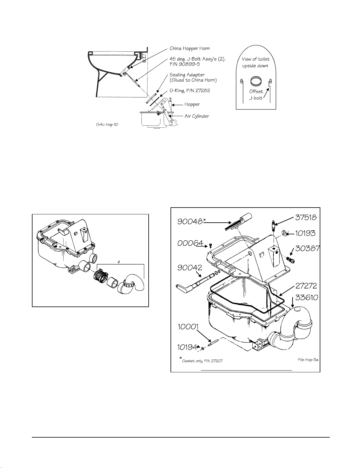
REAR DISCHARGE MODELS: Discharge line
should be connections at hopper with a No-Hub
Coupling (P/N 33324, provided). Do not glue or
connect fittings until fitting alignment has been
checked. Toilet discharge line must have a rise
(trap) (see ROUGH-IN DIMENSIONS) in order to
provided water trap seal when flapper is open.
CAUTION: do not apply stress to align outlet to
waste line. This will result in eventual seal damage.
DOWNWARD DISCHARGE MODELS: Toilet
mounts to floor with 1/4" closet bolts. Install screws
with a 3/8" nut driver. Screw on bolt caps to
mounting screws.
INSTALLATION AND START UP
1. Position and mount
the Toilet to floor.
See Rough-In
Dimensions.
2. For units with
Remote Flush,
position and mount
Remote Flush
Assembly to wall with Vacuum Breaker at least
6" above the rim of the toilet bowl. The
maximum water line distance between the toilet
and the Remote Flush Assembly is 4'.
3. Position and mount the Flush Activator to wall.
The maximum distance between the Flush
Activator and the Remote Flush Assembly is
72".
4. Connect the incoming water supply to the 3/4"
I.D. Hose Barb on the Remote Flush Assembly.
5. Connect the water line from Remote Flush
Assembly to the toilet spud assembly.
6. Assemble the Air Connecting Kit (P/N 93086)
provided and connect to incoming air supply.
Do not connect to flush Activator.
7. Turn OFF air shut-off cock at toilet.
8. Turn ON air supply at compressor.
9. Turn ON air shut-off cock at toilet to blow out
airlines for a few seconds. This procedure
should remove any debris or contaminants from
the airline. Turn OFF air shut-off cock.
10. Now connect airline to the top of the Flush
Activator. Turn ON air shut-off cock. Check
total installation for air leaks using soapy water.
11. Turn ON water. Check for water leaks.
12. Flush toilet four times, waiting twenty seconds
between flushes to get water through toilet and
operating regularly. To flush properly, hold
down handle until flapper opens.
13. Water level in bowl should be at top edge of
flapper opening.
14. If the toilet does not operate correctly or have
the proper water level in bowl, refer to adjusting
Toilet or Troubleshooting sections of this
manual.

LF-210 Manual P/N 24154 6 April, 2003
USAGE LUBRICATE
Light Every 5 years
Medium Every 2-3 years
Heavy Every year
ROUTIN E M AIN TENAN CE
Your Microflush toilet
has an air-operated
Air/Water Sequence
Valve which requires
periodic lubrication
with a silicone based
lubricant.
CLEANING
Use Micro-Clean Organic Spray Cleaner, P/N
24542. Caustic drain openers or non-biodegradable
cleaners should not be used if the toilet is connected
to a septic tank or Microphor biological sewage
treatment system. Clean as follows:
1. While depressing the flush activator, turn OFF
the water. Allow the bowl cleaner to flow into
the lower chamber. Keep the flushing activator
depressed.
2. Insert bowl brush into lower chamber and agitate
mixture.
3. Remove the bowl brush and release the flush
activator.
4. Turn the water ON and flush twice to rinse
thoroughly.
WINTERIZING
(out-of-service winter storage)
Shut OFF water to toilet. Flush toilet three times or
until water no longer flows into the bowl. Unhook
water supply at angle stop. Empty water in line into
receptacle. Shut OFF air supply to the toilet. The
unit is now prepared for freezing temperatures.
OPEN petcocks on drip legs and air receiver drain
after shutting down air compressor and isolating
airlines.
Pipe will protect flapper seal. If valve will not
operate with water off, hold flush lever down and
turn water on and off quickly to free valve action.
When the passage becomes clear, turn on the water
and press flush handle to start the flush cycle.
CLEANING BLEED-OFF PLUG
ASSEM BLY
Standard Flush:
Remove plug and clean with solvent; air blow dry.
Positive Flush:
Remove plug and clean with solvent; air blow dry;
remove and clean plug on Detent Valve.
Note: Use 5/32" or 4mm Allen wrench to remove
plugs.
CLEARING THE TOILET
If the toilet becomes plugged, shut off the water
supply, press the flush handle and hold. Flapper in
the bottom of the toilet will remain open until flush
handle is released. Check to see if the restriction
can be removed from lower portion of toilet with a
hooked wire, being careful not to damage the rubber
seal on the flapper or the mating surface on the
hopper. If obstruction can not be picked out with a
hook or tongs, use plunger by pushing in slowly and
pulling out quickly to pull object back into the
hopper. If necessary, turn air off and use a snake
inserted into a short plastic pipe placed in hopper.
Note: Bleed-off plugs on Air & Water Sequence
Valves and Detent Valves are different sizes that are
not interchangeable.

LF-210 Manual P/N 24154 7 April, 2003
TROUBLESHOOTING
Your Microflush®toilet is designed to give you years of trouble-free operation. Please check the following
before beginning any service or repair:
Water supply: 1 Is the water turned on?
2 Is the water pressure between 20 and 50 psi at the toilet for pressure water system?
3 Is there 6 feet minimum of head for gravity systems?
Fluctuating or high water pressure can cause intermittent problems with the toilet operation.
Check the water pressure at different times of the day (i.e., early morning, noon, evening) to
determine if you have fluctuating or high water pressure. A pressure-reducing valve installed on
the incoming water line will assure you have even pressure. Make sure no check valve is
installed before the Air/Water Sequence Valve.
Air system: 1 Is the air turned on?
2 Is the air pressure set at a constant 60-65 psi at the toilet?
3 Do you have any air leaks or kinks in the air system?
4Do you have water in the air system? This usually causes irregular timing.
Drain the compressor tank and check the filter regulator and drip leg(s) for water. To check for
water in Air/Water Seq. Valve, remove Bleed-Off Plug, put finger over screw opening and flush.
If water is present, it will squirt out. If water is detected, then the air cylinder and airlines must
also be drained.
Cycle time: 1 Is the flapper cycle time set correctly at 4-8 seconds?
2 Is the Bleed-Off Assembly plug blocked? (See page 6)
Trouble Possible Causes Correction
Flapper does not open.
Water does not flow.
Nothing happens.
1 No Air Supply to Microflush.
2 Water has accumulated in
Air/Water Sequence Valve
1 Supply compressed air at 60-65
psi at the toilet
2 See 'Check Air System" above.
Flapper opens and closes 4-8
seconds after handle is released,
but no water enters bowl.
1 No water supply to
Microflush.
2 Water turned off.
1 Supply water at 20-50 psi at
toilet
2 Open angle stop (shut-off valve).
Flapper opens when flushed, and
closes immediately when activator
is released.
1 Excessively high water
pressure.
2 Debris in check valve at base
of Air/Water Sequence Valve.
1 Install water pressure regulating
valve, set at 20-50 psi.
2 Clean Air/Water Seq. Valve.
Flapper opens and will not close. Bleed-Off Plug blocked. Remove, clean or replace, reinstall.
Water continues to run when
Microflush is not in use.
Foreign object is under water
valve in Air/Water Sequence
Valve.
Clean Air/Water Sequence Valve.
Reference Service Kit P/N 95057.
Water splashes when flushed. Water is too high in bowl. Reduce incoming water via angle
stop; Re-adjust cycle time.
Flush cycle is too long. Bleed-Off Plug blocked. Remove, clean or replace, reinstall.
Flush cycle is too short. Bleed-Off Plug hole too large or
related air lines leaking.
Remove, replace, and check for air
line leaks.
If other problems are encountered, please contact the factory: Toll Free: 1-800-358-8280

LF-210 Manual P/N 24154 8 April, 2003
VITREOUS CHINA COLOR CHART
ABC
China
Color Code
Round
Shell &
Lid
Elong.
Shell &
Lid
Lid
Only
Bolt
Caps
Beige SC4 44333 44334 99064-15 44371
Black N-5 44337 44338 99064-7 44076
Blue B-5 44343 44344 99064-13 44373
Bone S4 44039 44012 99064-3 93974
Gray 651 44329 44330 99064-5 44377
Ivory SC1 44327 44328 99064-24 44370
Oak N/A N/A N/A 99071 N/A
Pink SR2 44331 44332 99064-21 44368
Red R-5 44345 44346 99064-9 44372
Rose R3 44335 44336 99064-17 44375
White -- 44023 44010 99064 93972
Integral Valve Layout
Remot e Installation
EXPLODED VIEW S


LF-210 Manual P/N 24154 10 April, 2003
Rear Discharge Hopper
Downward Discharge Hopper
HOPPER REPLACEM ENT
CAUTION: Read this Entire Procedure Before Beginning Work!
1. Remove toilet from floor. Place toilet upside down on a sheet of cardboard or other padded surface.
2. Remove nuts from J-bolts on either side of Hopper, lift hopper away from bowl.
3. Remove O-ring from between hopper and sealing adaptor. Check that O-ring is not damaged.
4. Re-assemble in reverse order. MAKE SURE J-BOLTS ARE TIGHT! Proper torque specification is 4-6
inch/lbs.
HOPPER COMPONENTS
J - Optional P-trap, P/N 96029
To Change Flapper Gasket:
1. Turn water and air off.
2. Reach behind flapper to grasp gasket tails.
3. Pull tails out of slots to remove old gasket.
4. Installation is the reverse of removal.
5. Tails must be pulled all the way through to insure smooth surface.

LF-210 Manual P/N 24154 11 April, 2003
AIR CYLINDER ADJUSTM ENT INSTRUCTIONS
1. Remove hopper assembly.
2. Remove clevis pin retaining ring and
clevis pin.
3. Inspect the crank arm, clevis and clevis
pin for wear. Replace if required.
4. Hold the crank arm in the UP position
(flapper closed).
5. Fully extend the air cylinder and note the
position of the holes in the crank arm and
the clevis. The clevis hole should extend
half its diameter past the crank arm hole.
Adjust as necessary by turning clevis
clock-wise to loosen, counter clock-wise
to tighten. Make sure not to nick or
damage shaft.
6. Re-install hopper.

LF-210 Manual P/N 24154 12 April, 2003
FLUSH ACTIVATORS
95054 - Commercial Flush Activator
95557 - Palm Button Conversion Kit
95002 - Residential Flush Activator

LF-210 Manual P/N 24154 13 April, 2003
POSITIV E FLUSH ACTIVATOR (Commercial) Remote, P/ N 95087
The Detented Positive Flush Activator has been added (as an option) to our product line. It was developed in
order to overcome the necessity for the toilet user to hold the standard flush actuator in the deflected position for
a definite time (about 2 1/2 seconds) to insure full actuation of the toilet flush cycle. This option is
recommended for high use, public facilities.
It's principle of operation is as follows:
A) Under user control, a two way valve, requiring no more than 1/32" deflection for full flow, pilots a piston
drive detented mechanism.
B) The detent force is overcome after air pressure over the piston rises to 40 psi thus driving the standard flush
actuator to the full flush position.
C) The detent is reset after the entrapped air over the piston is bled to atmosphere. The bleed rate (and thus the
length of time the flush actuator is held in the flush mode) is controlled by the head bleed plug with a fixed
orifice size.

LF-210 Manual P/N 24154 14 April, 2003
AIR WATER SEQUENCE VALVE LUBRICATION
1. Disassemble valve from bottom to top by first unscrewing the Bottom Cap from the Main Body. Then, to
unthread the piston from the spool, insert a 3/16" hex into the hex opening at top of spool. Use an adjustable
end wrench on the oblong boss on bottom of piston to unscrew piston from spool and push spool up through
valve body to remove. Remove Top Cap and Water Seal. You will need a pair of needle nose pliers to
remove the Nut and Stem from the Bottom Cap.
2. Replace parts indicated in BOLD supplied with kit. Lubricate all O-Rings with lubricant provided. A light,
complete coating is all that is required as over lubrication will clog air passages.
3. Re-assemble valve from top to bottom as shown, with the exception of the Top Cap and Water Seal which go
on last. Make sure to align the yellow timing marks on Bottom Cap, Main Body and Water Body.
4. If desired, this valve may be returned to the factory for rebuilding and lubrication.

LF-210 Manual P/N 24154 15 April, 2003
AIR/ WATER SEQUENCE VALVE OPERATION

LF-210 Manual P/N 24154 16 April, 2003
Insert Terms & Conditions.
Other manuals for Microphor LF-210
2
Table of contents
Other Wabtec Toilet manuals
Popular Toilet manuals by other brands

DURAVIT
DURAVIT SensoWash 2121510001 Mounting instructions

Toto
Toto Aquia CST412MF Installation and owner's manual

Swiss Madison
Swiss Madison Sublime SM-1T205 installation instructions

Toto
Toto NEOREST NX MS900CUMFG installation guide

Toto
Toto CST446CUMFG Installation and owner's manual

miseno
miseno MNO120C installation instructions

Jungborn
Jungborn DUE 59 operating instructions

Cersanit
Cersanit AQUA Instructions for assembly and use

American Standard
American Standard MILANO TF-2041 installation manual

noken
noken CITY 100235046 N399999686 manual

Seima
Seima Limni Wall Faced Toilet Suite STO-309 installation guide

Geberit
Geberit AQUACLEAN TUMA COMFORT installation manual