Wabtec Microphor LF-210 Supplement

452 East Hill Road Fax: 707.459.6617
Phone: 707.459.5563 www.microphor.com 24533.WPD
Toll Free: 1.800.358.8280 www.wabtec.com 10/19/01
Model LF-210 Model LF-219
Model LF-310 Model LF-320
Microflush Half Gallon Toilets
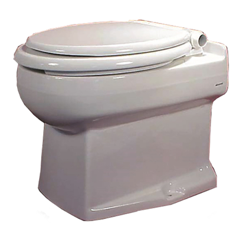
Marine Heads
Air Operated
Installation/Service Manual
P/N 24533

Marine Head Manual P/N 24533 2June 25, 2002
THANK YOU FOR PURCHASING A
MICROPHOR®PRODUCT!
Your Microflush®Marine Head is designed to
provide you with years of reliable service while
using only two quarts of salt or fresh water per
flush. Please read this Owner's Manual completely
prior to installation of your Microflush Marine
Head. This will familiarize you with all of the
proper installation and operation requirements.
CUSTOMER SERVICE - Please contact your
local Microphor dealer for parts and service. For a
list of dealers, please contact Microphor at the
addresses listed on the cover of this manual.
AIR SYSTEM
Filter-regulators are
available in a variety of
sizes and types. Their
purpose is to remove
water, oil and other
foreign matter from the air
line and to maintain a
constant pressure at the
toilet of 60-65 PSI. The following steps must be
observed to assure moisture will be removed from
the airline:
1. Drain air compressor receiver regularly. Most
water tends to accumulate at this point.
2. Install drip legs with condensate drains at all low
points in air piping.
3. Whenever possible, grade all airlines back to the
air receiver or drip leg assembly and drain
regularly.
4. The air supply to your Microflush Marine Head
must be taken from the top of the main or branch
air line.
AIR COMPRESSOR
Be certain compressor crankcase has proper oil
levels. Locate the compressor in a clean, dry, well
ventilated location. Size compressor according to
separate Air Compressor Specifications Sheet.
ITEM LF-210 LF-219 LF-310
LF-320
Air Line Connection Compression 1/4" 45o
Flare Fitting
Water Line
Connection
1/2"
MIPS
Slip Joint
Nut
3/4" ID
Hose
Barb
1/2" FNPT
Fitting
Drain
Connection
Down
12"
(305mm)
on center-
line
2.25"
(57mm);
3.6"
(91mm)
off
center-
line
Not
Available
Rear 1-1/2" outlet, 3/4"
(19 mm) off
centerline Centerline
Remote Valve
Assembly
Must be mounted so vacuum
breaker is located 6" above rim of
toilet bowl.
1 PRE-INSTALLATION
Following procedures apply
to all Microflush models
unless otherwise noted.
Remove your Marine Head
from box carefully.
Integral Models - Install toilet seat and flush
handle before mounting Microflush to floor.
Seat is not included with LF-210 and LF-219
models. Bolt caps and closet screws are
provided with LF-210 and LF-219 models.

Marine Head Manual P/N 24533 3June 25, 2002
2AIRLINES
All piping
supplied by
customer is to
conform to
U.S.C.G.
requirements
relating to
water tight
decks and
bulkhead (46CFR56.69)
Be sure airline from compressor is of sufficient
size, based on length of pipe run to head. We
suggest 3/8" air line up to 40', 1/2" air line up to
75', and 3/4" air line for over 75'.
Install a filter-regulator assembly in incoming
airline. Place the filter-regulator as close as
possible to the first Microflush Marine Head and
in an accessible location.
Set filter-regulator so that 60-65 psi constant is
available at the head. Install an in-line air dryer,
Microphor P/N 30054 or combination
filter/regulator/dryer, P/N 94036.
Assemble the Air Connecting Kit provided and
connect to incoming air line with shut-off valve
between bulkhead and toilet. For LF-210
Models, use Air Connecting Kit P/N 93086, and
for LF-219 Integral Models use Air Connecting
Kit P/N 95172. The plastic airline provided goes
from the air supply to the Flush Activator. On
integral models, the plastic air line enters the
Microflush through the back wall or up through
the floor under the unit. Make sure air is OFF at
air compressor.
DO NOT CONNECT TO FLUSH
ACTIVATOR YET!
3 WATER LINES
Use a 1/2" water line and install a water shut-off
valve (angle stop) between bulkhead and toilet.
Water at the head must be regulated at an even
pressure between 20 to 50 PSI for Microflush to
operate properly. Optimum pressure is 35 PSI.
DO NOT CONNECT WATER LINE TO
MICROFLUSH YET.
INSTALLATION PROCEDURES
4 DRAIN CONNECTION - See Rough-in
Dimensions
For direct overboard discharge, contact
Microphor or your dealer.
When using a 1-1/2" (38.1 mm) discharge line,
each toilet must go individually to the MSD or
holding tank. Do not connect more than one
toilet to a 1-1/2" (38.1 mm) discharge line.
If a vertical rise is required, the vertical rise must
be at the toilet. The maximum vertical rise is
36". The maximum horizontal run is 30 feet
(9.14 meters) and must slope a minimum of 1/8"
per foot (1 in 100) towards the MSD or holding
tank. For 1-1/2" lines, reduce horizontal pipe run
2 feet (.68 meters) per 90oelbow. Use long
sweep elbows, do not use 45oelbows. Do not
use the inverted P-Trap with a vertical rise.
When multiple heads are installed, a vented 3"
gravity collection line is to be used with not more
than 4 heads per 3" line. Manifold the 1-1/2"
lines into the 3"collection line and provide a
grade of at least 1/4" per foot towards the MSD
or holding tank. Vent 3" line at the manifold
point.
Holding tank or MSD must be vertically vented
to atmosphere via 3" vent, terminating at highest
point possible. Limit the number of 45oor 90o
fittings. Do not install loops on end of vent.
For holding tank installations, consider installing
a power fan sized so that a volume of air equal to
the empty tank volume is exchanged every 30 to
60 seconds. The negative pressure shall not
exceed -1.3 psi. This will allow for good air
flow out the vent.
Your Microflush Marine Head discharge line
must have a rise (trap) in order to provide back
pressure during the flush cycle - see Rough-in
Dimensions on pages 14-15.
Caution: Do not apply stress to align
Microflush rear or downward discharge
outlet to waste line. This will result in eventual
damage to seal between Hopper and Toilet Bowl,
causing leaking. Do not use the P-Trap with a
vertical rising waste line.
LF-210 Downward Discharge Model: Rest Microflush on it's back on a padded surface (e.g.

Marine Head Manual P/N 24533 4June 25, 2002
shipping box). Center wax ring over Hopper
Flange. Turn Microflush Marine Head over, lift
up, and center it with the horn of the wax ring into
standard floor flange located on centerline 12"
from wall. Compress the wax ring by applying
weight to your Microflush Marine Head. A second
standard wax ring may be added if floor is uneven.
If Hopper Flange hits floor flange, grind it down
for added clearance, as any contact will break seal
between Hopper and Toilet Bowl, causing leaking.
All Rear Discharge Models: Install inverted
P-Trap supplied with Microflush Marine Head. Do
not glue or connect fittings until fitting alignment
has been checked.
Caution: Outlet of LF-210 and LF-219 Models is
3/4" off centerline. Make sure head discharge and
waste line are in line, not off set.
When using a 1-1/2" discharge line, a vertical lift
of 36 inches can be achieved in single head
applications. The vertical rise must be at the toilet.
This vertical application is not advised for
commercial, high use applications. Do not use the
P-Trap with a vertical rising waste line. Please
contact the factory for further information.
LF-219 Model: For downward discharge, use
molded P-Trap hose supplied. For rear discharge
use inverted P-Trap. See page 9 for part numbers.
Remote Models: Position and mount the Remote
Valve Assembly making sure the Vacuum Breaker
is at least 6" above the rim of the Microflush
Marine Head bowl. Measure air and water lines to
make sure Remote Valve is mounted within
connection distance to Microflush Marine Head.
Run water and the three air lines from the Remote
Valve Assembly to Microflush.
Caution: For Remote Flush Activators, make sure
inside wall thickness does not exceed 1/2" or large
mounting nut will restrict movement of flush
handle.
Mount toilet bowl to floor. LF-210 and LF-219
models mount to floor with 1/4" closet bolts
provided. Screw on bolt caps to mounting screws.
Model LF-310 and LF-320 models are bolted to
floor, bolts not provided.
LF-320 Models:
1 Remove side panels to facilitate mounting toilet.
2 Connect 7' water line to Spud fitting at the back of
the toilet bowl.
3 Run water and the three air lines from the
Microflush through wall access (maximum 7
feet).
4 Position toilet and connect hopper discharge
outlet to waste line.
5 Bolt toilet to floor and attach back plate to wall.
Do not reposition toilet after it is connected to
the waste line as this may break the seal between
bowl and Hopper and cause a water leak.
Re-install side panels on toilet.
6 Connect the three air supply lines to the
Air/Water Sequence Valve, color coded lines to
matching color coded fittings.
7 Mount Remote Valve Assembly at least 6" above
the rim of the bowl, and mount the Flush
Activator assemblies at desired location on wall.
5 WATER CONNECTION
Never install a check valve on the inlet side of
the Microflush head.
Integral Models - Connect incoming water from
angle stop to water connector. Make sure
WATER IS OFF at angle stop.
LF-210 Models -water supply connector is made
of nylon-plastic. Be careful not to cross threads.
LF-219 Models - if integral model is connected
to a potable water source, the unit requires
installer to provide a Back Flow/Cross
Contamination Prevention device. Please check
applicable jurisdiction for requirements before
installation.
LF-310 Models - use back-up wrench on water
inlet. DO NOT allow inlet fitting to turn and be
forced into Air/Water Sequence Valve.
Remote Models - Connect incoming water from
angle stop to Microflush Hose Barb on the
Remote Valve Assembly. Connect the water
line from Remote Valve Assembly to the Flush
Rim Spud Assembly. Make sure WATER IS
OFF at angle stop.
Marine Head Manual P/N 24533 5June 25, 2002
START UP
1 Turn air ON air supply at
compressor.
2 Turn air ON at air
shut-off cock (near but
not connected to Flush
Activator) to blow out
airlines for a few seconds.
This procedure should
remove any debris or contaminants from the
airline. Turn air OFF at shut-off valve.
3 Connect airline to Flush Activator. Make sure air
shut-off valve is installed next to Flush Activator.
Do not over-tighten fittings.
4 Turn ON air shut-off cock. Check total installation
for air leaks using soapy water.
5 Turn ON water. Check for water leaks.
6 Flush you Microflush Marine Head four times,
waiting twenty seconds between flushes to get
water through system and operating regularly. To
flush properly, hold down Flush Activator Handle
or Button until flapper opens.
DOUBLE CHECK
1 Air pressure at Microflush Head is at 60-65 psi.
2 Water Pressure at Microflush Head is between
20-50 psi, 35 psi optimal.
3 Water level in bowl should be at top edge of
flapper opening.
If your Microflush does not operate correctly, refer
to troubleshooting sections.
FLUSH CYCLE ACTIVATORS
There are two types of Flush Activators:
Standard - hold handle or button down for 1
second.
Positive - barely push handle or button to
activate.
CLEANING BLEED-OFF PLUG
ASSEMBLY
Standard Flush:
Remove plug and clean with solvent; air blow dry.
Positive Flush:
Remove plug and clean with solvent; air blow dry;
remove and clean plug on Detent Valve.
Note: Use 5/32"or 4mm Allen wrench to remove
plugs.
Note:
Bleed-Off Plugs on Air & Water Sequence Valves
and Detent Valves are different sizes that are not
interchangeable.
MAINTENANCE/CLEANING/CLEARING/
WINTERIZING
ROUTINE MAINTENANCE
Other manuals for Microphor LF-210
2
This manual suits for next models
3
Table of contents
Other Wabtec Toilet manuals
Popular Toilet manuals by other brands

American Standard
American Standard CONCEPT Cube TF-2704 installation manual

BIOLAN
BIOLAN ECO Instructions for installation, use and maintenance

Thetford
Thetford C260 Series user manual

KELISS
KELISS T162A Series instruction manual

Silent Venus
Silent Venus SVP600 Installation & maintenance

Kohler
Kohler K-22241K Installation and care guide