MICROFLUSH Toilet Manual 2 March 2005
THANK YOU FOR PURCHASING A
MICROPHOR PRODUCT!
Your Microflush®toilet is designed to provide you with
years of reliable service while using only two quarts of
water per flush. Please read this Owner’s Manual com-
pletely prior to installation of your Microflush toilet. This
will familiarize you with all of the proper installation and
operation requirements.
CUSTOMER SERVICE
Please contact your local Microphor dealer for parts and
service. For a list of dealers, please contact Microphor at
1-800-358-8280 or visit our website at
www.microphor.com.
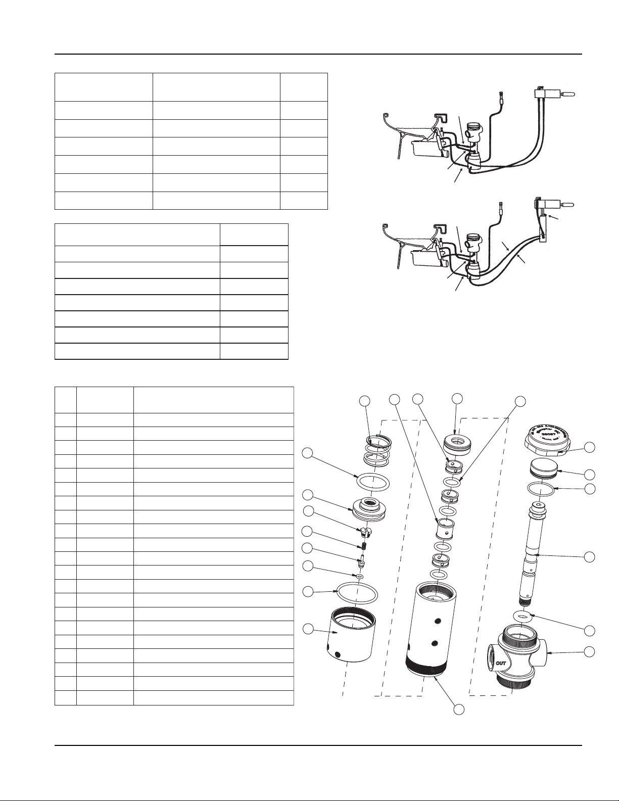
AIR SYSTEM
Filter-regulators are available
in a variety of sizes and types.
Their purpose is to remove
water, oil and other foreign
matter from the air line and to
maintain a constant pressure
at the toilet of 60-65 PSI.
The following steps must be
observed to assure moisture
will be removed from the
airline:
1.Drain air compressor receiver regularly. Most water
tends to accumulate at this point.
2.Install drip legs with condensate drains at all low
points in air piping.
3.Whenever possible, grade all airlines back to the air
receiver or drip leg assembly and drain regularly.
4.The air supply to your Microflush toilet must be taken
from the top of the main or branch air line.
AIR COMPRESSOR
Be certain compressor crankcase has proper oil levels.
Locate the compressor in a clean, dry, well ventilated
location. Size compressor according to separate Air
Compressor Specifications Sheet.
PRE-INSTALLATION
The following procedures apply to all Microflush models
unless otherwise noted. Remove your toilet from box
carefully. Integral Models - Install toilet seat and flush
handle before mounting Microflush to floor. Seat is not
included. Bolt caps and closet screws are provided.
1. AIR LINES
If used in Marine applications, all piping supplied by
customer is to conform to U.S.C.G. requirements relating
to water tight decks and bulkhead (46CFR56.69)
Be sure airline from compressor is of sufficient size,
based on length of pipe run to head. We suggest 3/8" air
line up to 40', 1/2" air line up to 75', and 3/4" air line for
over 75'.
Install a filter-regulator assembly in incoming airline.
Place the filter-regulator as close as possible to the first
Microflush toilet and in an accessible location.
Set filter-regulator so that 60-65 PSI constant is avail-
able at the toilet. Install Microphor combination filter/
regulator/dryer, P/N 94036.
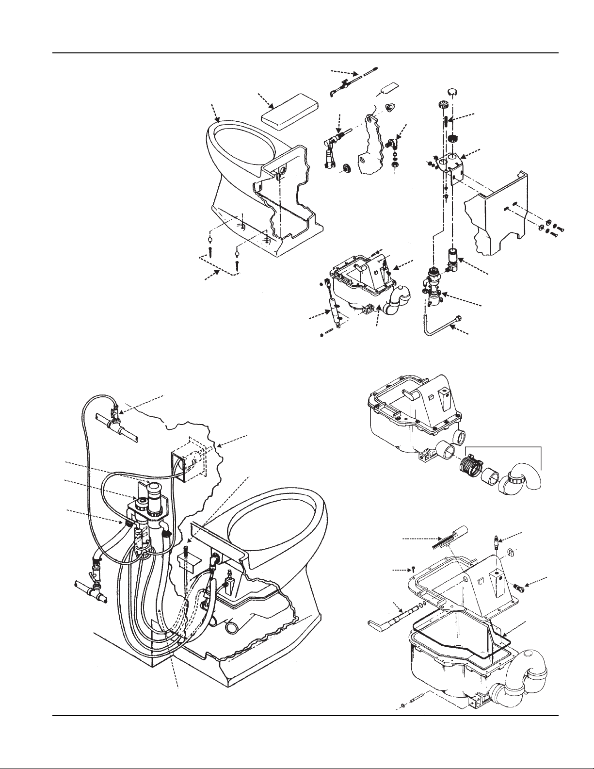
Assemble the Air Connecting Kit provided and connect to
incoming air line with shut-off valve between bulkhead
and toilet. For LF-210 Models, use Air Connecting Kit
P/N 93086, and for LF-219 Integral Models use Air
Connecting Kit P/N 95172. The plastic airline provided
goes from the air supply to the Flush Activator. On
integral models, the plastic air line enters the Microflush
through the back wall or up through the floor under the
unit. Make sure air is OFF at air compressor. DO NOT
CONNECT TO FLUSH ACTIVATOR YET!
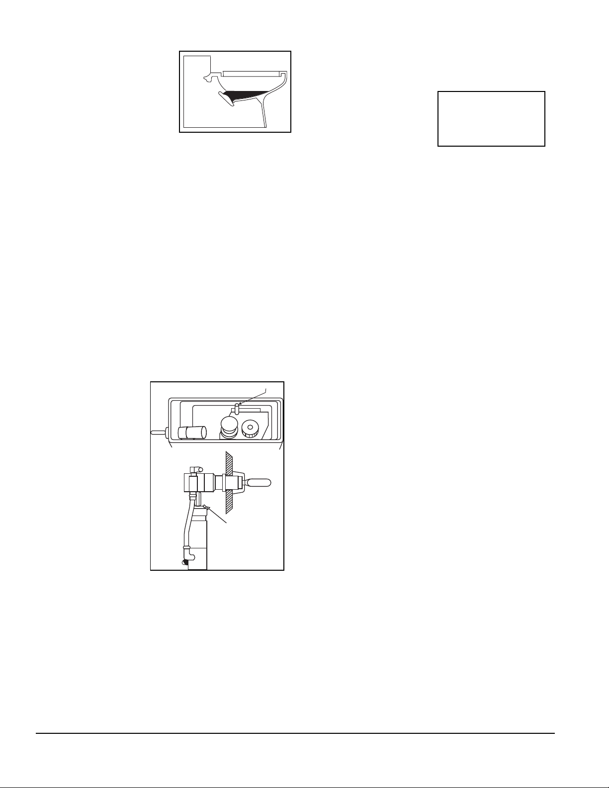
2. WATER LINES
Use a 1/2" water line and install a water shut-off valve
(angle stop) between bulkhead and toilet. Water at the
toilet must be regulated at an even pressure between 20
to 50 PSI for Microflush to operate properly. Optimum
pressure is 35 PSI. DO NOT CONNECT WATER
LINE TO MICROFLUSH YET!
INSTALLATION PROCEDURES
3. DRAIN CONNECTION - See Rough-In Dimensions
FOR ALL INSTALLATIONS:
LF-210 Downward Discharge Model: Rest Microflush
on its back on a padded surface (e.g. shipping box).
Center wax ring over Hopper Flange. Turn Microflush
toilet over, lift up, and center it with the horn of the wax
ring into standard floor flange. Compress the wax ring by
applying weight to your Microflush toilet. A second
standard wax ring may be added if floor is uneven. If
Hopper Flange hits floor flange, grind it down for added
clearance, as any contact will break seal between Hopper
and Toilet Bowl and cause leaking.
Note: Discharge on toilet is 13.25 (+/- 0.5”) from
back. See rough in dimensions.
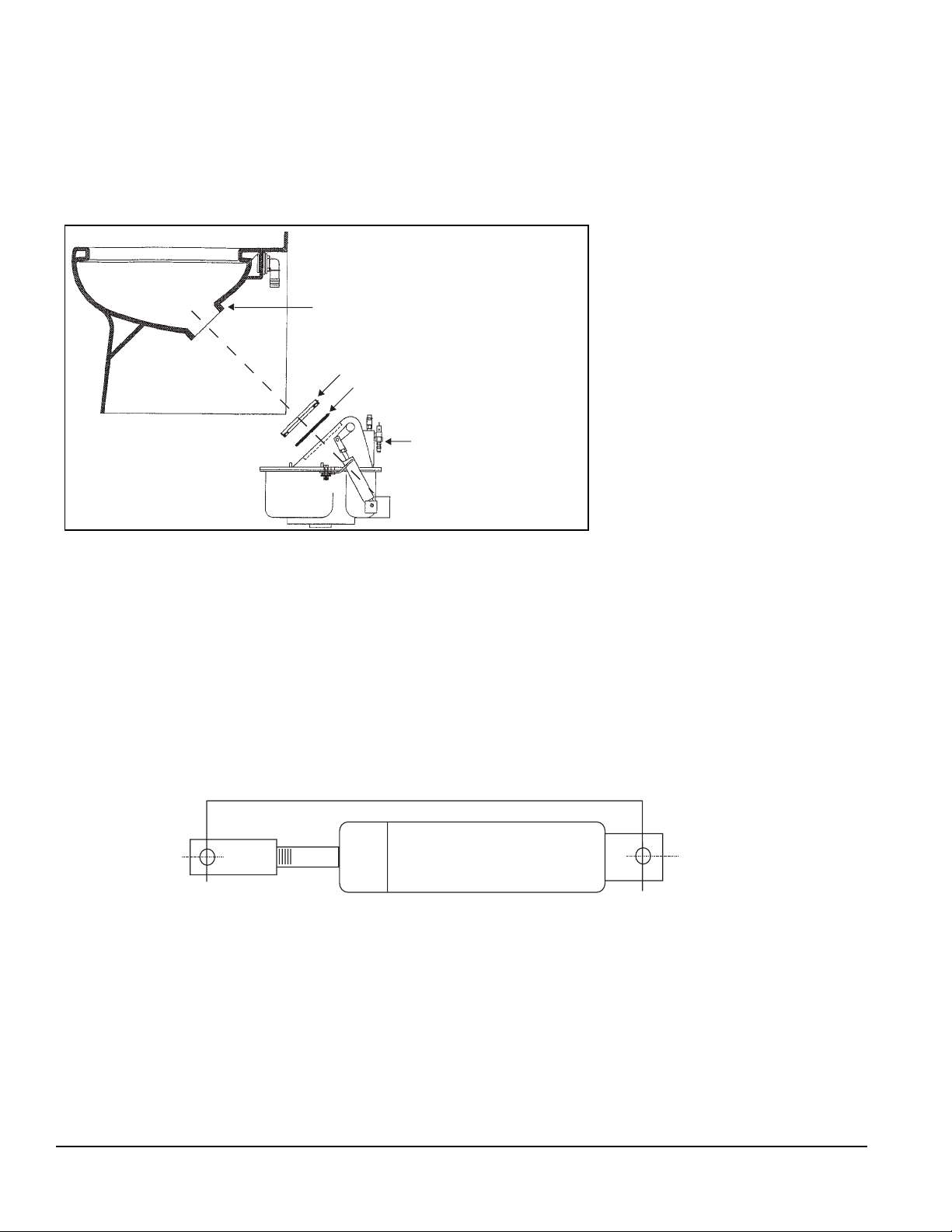
Condensate Drain
Drip Leg
Filter-Regulator
Air Connection
Slope
ile: airline