WADER Goldseal Plus User manual

Operators Manual
Rev: GSW-Plus 2020 (K32)

Goldseal Plus
Operators manual
Features
The new Plus machine use a powerful microprocessor PID (Proportional plus Integral plus Derivative) controller utilizing flash memory processors which allow
custom features and high standard of temperature accuracy.
PID controllers prevent oscillation around the temperature set point and adjust the power output to avoid overshoot and offset, for a more reliable and stable
temperature. Dual display of temperature and time dwell. R controlled heating element.
Unpacking & Set-up
Safety First ~ NEVER stand over the machine when in the clamped / closed position.
Remove the heat press from the packing case and retain all the packing.
Mount the press on a solid surface ensuring it is located near a mains outlet.
Plug the mains cable into the rear of the machine and connect to: - 240 Volt AC, single-phase mains supply (standard wall socket)
Depress the on / off switch and the control will illuminate as below and perform a self diagnostic for a few seconds.
.
The machine will now start to heat up. Please note for the later part of the heating cycle approximately 10°C before the set point the heating
cycle will slow down this is the PID control bringing the temperature up by pulsing the element supply to avoid temperature overshoot
The first line of the controller display (in red) is the current temperature.
When the machine is first switched on it will display the temperature of the platen and gradually heat up to the set point.
The controller on the left is indicating 210°C this means the machine is ready to use (204°C post 2019 machines).
The second display (green) line is the timer set point in seconds currently set to 8 seconds.
The machine is delivered set to standard factory settings as above but you may wish to change these for different materials or marking products.
You may check your settings at any time simply by pressing the
key and the temperature set-point will be displayed, press
again and the timer
set-point will be displayed, press
a third time and the control will loop back to the temp set point simply leave the control for a few seconds and display will revert
to monitoring the temperature of the machine.
To Change the Temperature & Timer Set oints
2
Press the
button once to enter the temperature set point
If you want to alter the
temperature
set point use the arrow keys up &
down followed by the
key to store
the new temperature.
The controller will now display the
preset dwell time
Again if you want to alter the timer set
point tr.t1 use the arrow keys up &
down followed by the
key to store
The display on the controller will loop back to the temperature set point.
If you are happy with the setting then simply leave the controller for a few seconds and the
display will return to monitoring the platen temp and dwell time.
Or to leave the te perature set point as
it is si ply press the
key again to
enter the ti er set point
SP 1 – et point for platen temperature
210 – Current temperature set point
Or to leave the ti er set point as it is
si ply press the
key again.

Goldseal Plus
Operators manual
To Operate the Hand ress
Ensure that the temperature & Timer setting are correct.
You ay check your settings at any ti e si ply by pressing the
key and the te perature set-point will be displayed, press
again and the ti er
set-point will be displayed, press
a third ti e and the control goes back to the standard screen display
Place the part of the garment/article to be marked onto the silicone pressure pad.
Pull the handle forward into the locked position, ensuring the garment is firmly clamped between the heat plate and pressure pad. (Make sure that your
hands are away from the heated platen when using the heat press).
The timer display will now start a countdown.
After completion of the above the buzzer will sound when the pre-set time has elapsed and t.End (timer end) will be displayed, the handle
should then be lifted back to it full extent.
Before operating the machine at the start of each day carry out a sealing procedure without any garment or transfers this will remove any
moisture from the pad.
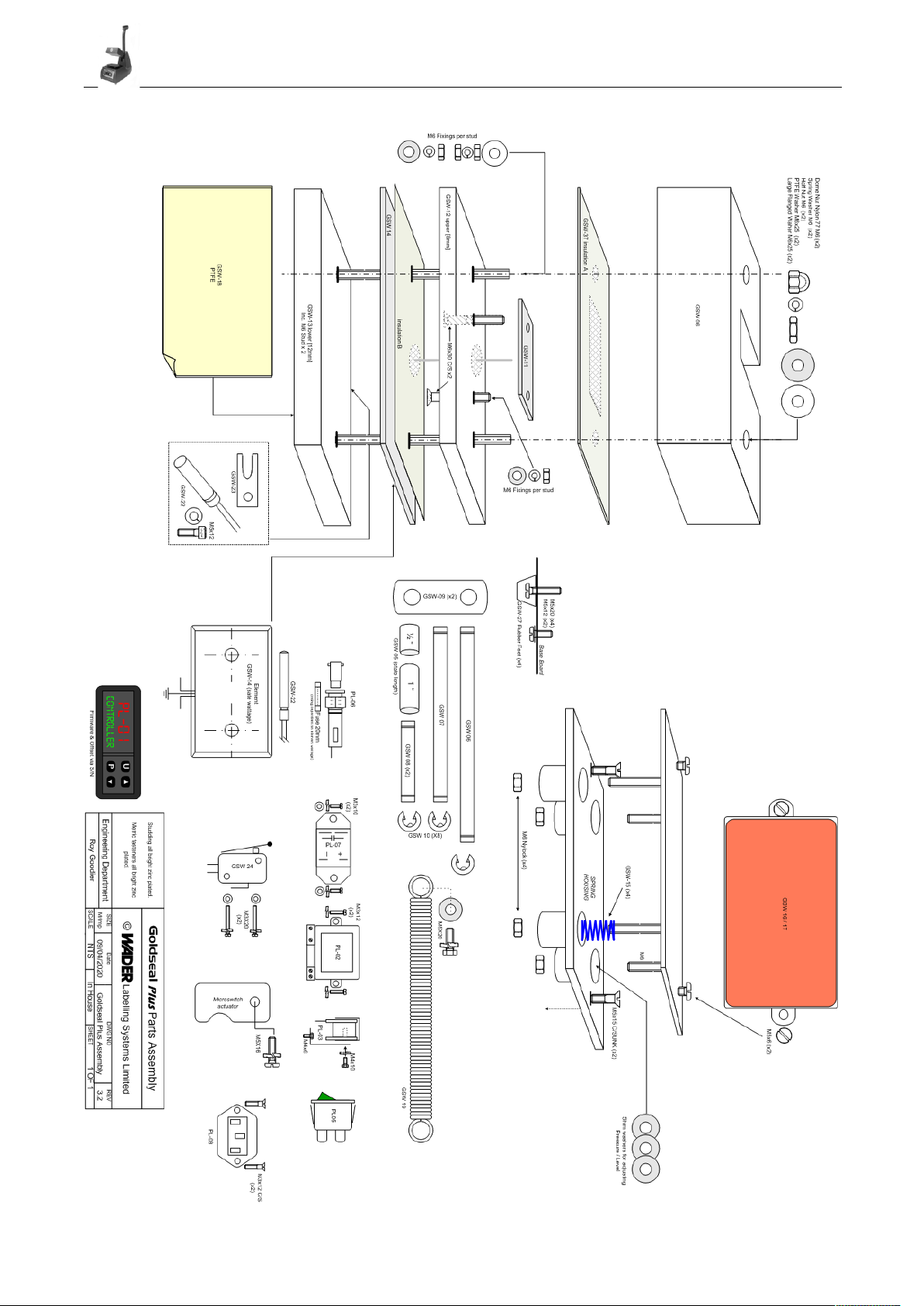
ressure ad Assembly
The silicone pressure pad and assembly should be maintained and kept in good condition at all times.
A worn silicone pressure pad will effect the quality of transfer marking / fusing and should be replaced when showing signs of wear. (See parts list).
After a long duration of time it may be found that there is a loss of pressure through the pressure pad assembly, this can be rectified by replacing the pressure springs
located under the pressure plate.
Never allow the heat plate to rest on the silicone pressure pad when the press is not in use.
TFE Heat late Cover
A PTFE cover is fitted to the heat plate, which allows the surface to be wiped clean should it become marked.
New PTFE covers may be fitted to the heat plate when ARM (not hot) and has been cleaned to remove residue of the old PTFE.
Design Change
With a policy of constant improvement and/or modifications to meet changing conditions, the right is reserved to change the design and/or specifications at any time
without prior notification, therefore no guarantee can be given as to the accuracy of the information contained in this instruction book.
Guarantee
This press is guaranteed to be free from defects in materials and workmanship ** for a period of 12 months from the proven date of delivery or installation.
hould, in our opinion, any part of this press be defective in materials or workmanship it will be replaced or repaired free of charge (excluding any travelling costs /
carriage costs which will be charged at our discretion) provided that the press has been installed and operated in the correct manner and not subjected to misuse.
A charge will be made for any costs incurred if a reported fault on the press is found to be due to incorrect installation, operation and/or incorrect materials being
used, as it is the responsibility of the press user to ensure the suitability of the materials operating through the press.
** Exclusions - Pressure Pad GSW-16, PTFE GSW-18
Application details for Wader roducts
Your press should have the following settings: -
Temperature: - 204 °C (application dependent)
Pressure: - 20 PSI
Time Dwell: - 8-10 seconds
The above is only a basic guideline you may need to change settings for special materials. To alter the settings see page 3.
e recommend that THERMAL materials / clothing are not used on this heat press.
It is also recommended not to apply heat seal labels to existing garment labels.
Contact Sales For Special Material Settings.
Specifications
upply Voltage 230 / 240 Volt AC. 500watt (8x6 - 700 Watt)., Microprocessor PID Temperature/Timer Control Unit.
Allowances should be ade when P.A.T. testing.
240v Mica plate heating element including 40" leads and integral earth.
Cast Aluminium construction. Dry weight of 14 kg (8x6 15 kg).
Maintenance
Lubricate toggle linkage at regular intervals with light machine oil, this will ensure a long life of the toggle assembly and also a smooth operation.
Keep top PTFE cover in good condition.
Ensure that the silicone pad is in good condition.
Never clean the machine with abrasive cleaners or solvents that may damage the product.
Check all fasteners are tightened to the correct torque. This is particularly important with the heat plate fixing as these are under extreme heat and strain.
This machine is designed for application of heat-seal transfers, tape, badges and patches only.
Please ensure the manufacturers operating instructions are adhered to.
A colour copy of this manual plus all the ader machinery can be downloaded from the website www.wader.co.uk
e recommend a qualified engineer inspect the machine at six Monthly intervals
3

Goldseal Plus
Operators manual
Fault Finding
No Mains light Or Control Display
Check the supply to press and condition of fuses (front panel & plug)
Is the press switched on?
Control Unit Transformer output of 12vac ?
Heat plate fails to get warm (refer to fig.2)
Does the element have continuity? *
Does the probe have resistance?
Is the relay switching over? (check R, and coil supply)
RTD robe.
To test the probe condition remove completely from press and measure
the resistance at room temperature using a multimeter.
Then warm the probe if the resistance changes the probe is working correctly.
This will only give you an approximation of the condition of the part.
Sealing ressure Low.
everely worn pad
Over compressed springs
Toggle links worn
Timer Buzzer
Toggle arm not making contact with micro-switch
Faulty micro-switch, check switching with meter.
Buzzer faulty check AC power supply to buzzer 230VAC.
Safety First hen working on the heat press remember to always DISCONNECT the mains supply
before removing covers or guards. Never allow your hands to be in a position that they may be trapped
by the heat plate when you bring the handle down.
4
Controller Error Codes
Out of range signals
The upper display shows the OVER-RANGE and UNDER-RANGE conditions with
the following indications:
Over-range Under-range
The sensor break will be signalled as an out of range
NOTE: When an over-range or an under-range is detected, the alarms operate as
in presence of the maximum or the minimum measurable value respectively.
To check the out of span Error condition, proceed as follows:
1) Check the input signal source and the connecting line.
2) Make sure that the input signal is in accordance with
the instrument configuration.
Otherwise, modify the input configuration
3) If no error is detected, send the instrument to your supplier to be checked.
ErAT - Fast Auto-tune can’t start. The measure value is too close to the set point.
Push the P button in order to delete the error message.
NoAt - Auto-tune not finished within 12 hours.
ErEP- Possible problem of the instrument memory.
The messages desappears automatically.
When the error continues, send the instrument to your supplier

Goldseal Plus
Operators manual
OEM arts List Goldseal 4x3 (Optional Sizes 5x5, 6x4 & 8x6)
PL-01 CONTROL UNIT (ascertain software / hardware
version before ordering
PL-02 TRANSFORMER (controller
PL-03 BUZZER 240VAC
PL-07 CONTROL RELAY (ssr
PL-05 MAINS SWITCH (Green Illuminated
PL-06 FUSE HOLDER
GSW-01 BODY (Main Casting
GSW-02 LEVER HANDLE (Operating Arm
GSW-03 TOGGLE ARM
GSW-04 PLATEN COVER
GSW-05 BUSHES (Oilite Bush
GSW-06 PIN 125mm
GSW-07 PIN 112mm
GSW-08 PIN 38mm
GSW-09 TOGGLE LINKS (Links are chemical blacked
GSW-10 CIRCLIPS
GSW-11 GASKET L-21 (Heat plate to arm
GSW-12 HEAT PLATE TOP
GSW-13 HEAT PLATE LOWER
GSW-14 ELEMENT METAL CLAD (500 Watt @ 240Vac
GSW-15 PRESSURE SPRINGS
GSW-16 SILICONE PRESSURE PAD
GSW-17 PRESSURE PAD PLATE (grade 525
GSW-18 PTFE (pack of 5
GSW-19 MAIN TOGGLE SPRING (Arm return spring
GSW-22 RTD PROBE
GSW-23 PROBE RETAINER
GSW-24 MICRO-SWITCH (Timer actuation
GSW-26 BASE BOARD
GSW-27 RUBBER FEET
GSW-28 MAINS LEAD
PL-08 MAINS INLET FlANGE FIXING 10amp
GSW-32 PACKAGING
GSW-33-plus INSTRUCTION BOOK
GSW-34 SET OF SCREWS (Complete
GSW-36 MICRO-SWITCH GASKET
GSW-37 HEAT PLATE INSULATION GASKET A
GSW-38 HEAT PLATE SHIM
GSW-39 Element Insulation B
GSW-55-04 5x5 PLATEN COVER
GSW-55-16/17 5x5 SILICONE PAD AND PLATE
GSW-55-18 5x5 PTFE
GSW-64-04 6x4 PLATEN COVER
GSW64-16/17 6x4 SILICONE PAD AND PLATE
GSW-64-18 6X4 PTFE
GSW-86-04 8x6 PLATEN COVER
GSW-86-16/17 8x6 SILICONE PAD AND PLATE
GSW-86-18 8x6 PTFE
GSW-86-14 8x6 ELEMENT 700 WATT
GSW-86-19 8x6 MAIN TOGGLE SPRING
GSW-86-40 HEAT PLATE INSULATION
5
PL-03
PL-07
PL-02
PL-06 PL-05
PL-01
Fig 1

Goldseal Plus
Operators manual
6

Goldseal Plus
Operators manual
7
Table of contents