SAFETY INSTRUCTIONS
Carefully read instruction manual with particular reference to the following
instr.uctions:-
a)
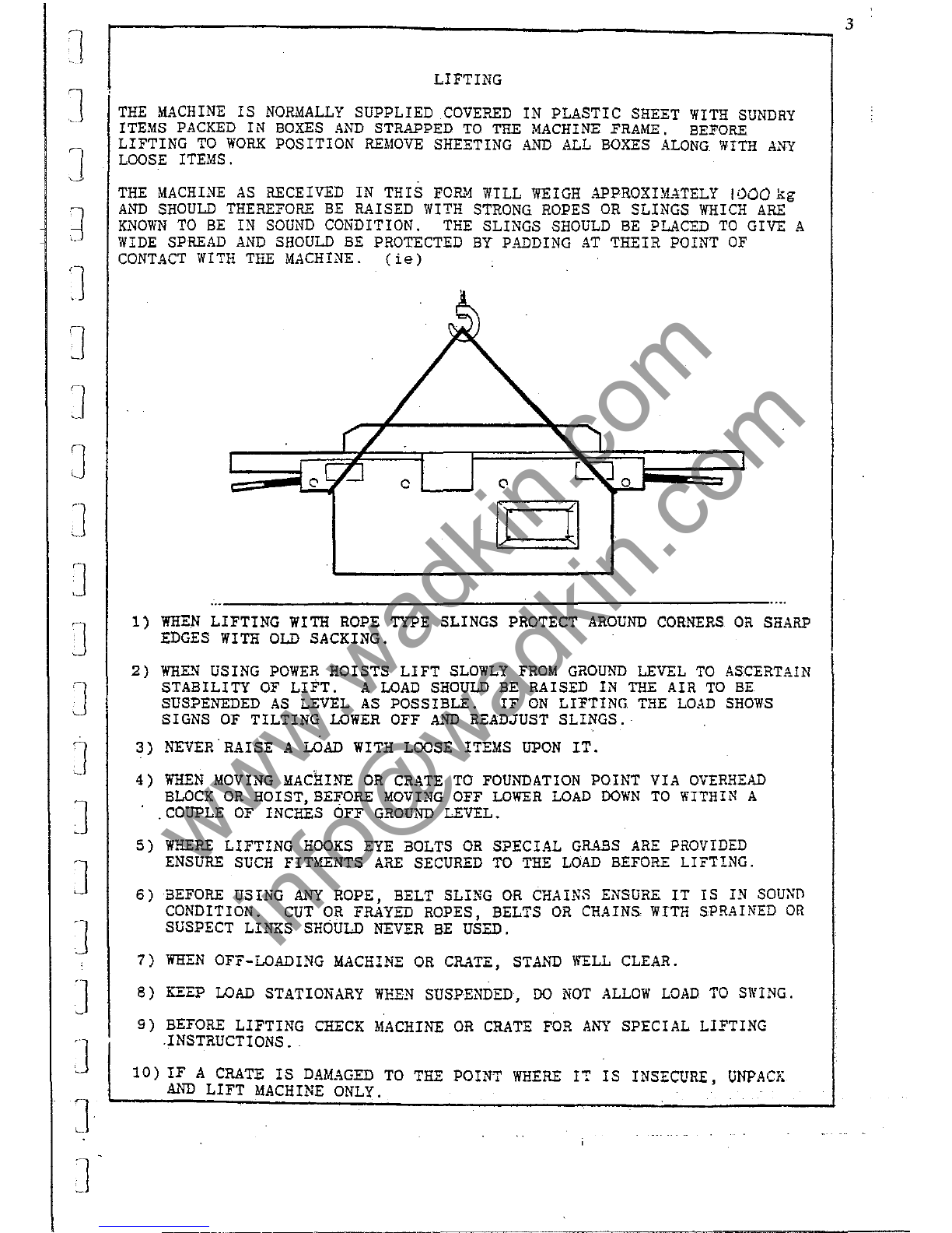
Slinging,
ie,
safe lifting limits for slings, etc.
b)
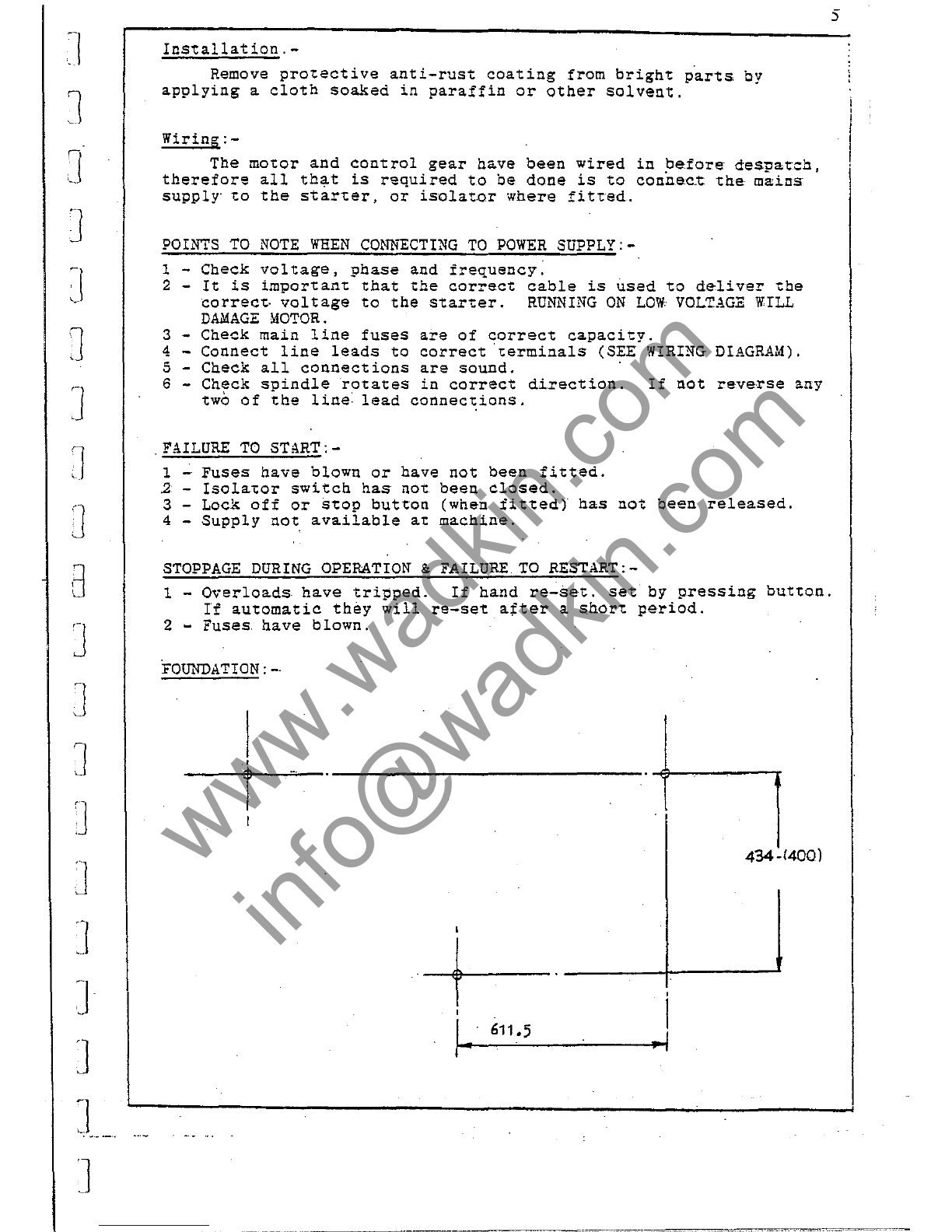
Installation and foundation,
ie,
safe working area of machine,bolt positions,
etc.
c)
Wiring details, ie, connection
of
machine to mains supply, fuse details, etc.
d) Machine controls and operating instructions.
Ensure tooling
is
of
the
correct type for use with
the
machine and cutters are
securely fixed in position.
Select correct spindle speed and feed rate relevant to the tooling being used.
Set all guards correctly
and
ensure they are securely fixed
in
accordance with the
current regulations.
Use suitable jigs, fixtures and feeding devices etc., (push stick, etc.,) where
appropriate.
Referto .8S.6854, Part 1, "Safeguarding Woodworking Machines'
UK
market and
subsequent parts for specific machines for safe working practices.
During Machining
Wear suitable protective equipment, where necessary, eg, goggles, ear defenders
and dust mask.
Ensure
all
moving
parts
of
the machine are stationary before setting, cleaning
or
making any adjustments.
Report immediately
to
a person in authority any machine malfunction
or
operator
hazard. Do not attempt
to
repair the machine unless authorised
to
do
so.
Ensure machine
is
electrically isolated before any maintenance/cleaning
work
commences.
NOISE
lEVELS
This
machine,
undercertain conditions,
will
em~
noise
levels
in
excess
of
85d8(a).
Noise
levels
will
be
affected
by
the
environment
in
which
the
machine
operates
the
timber
being
machined,
tooling,
machine
setting
and
dust
extraction.
Further
information
available
from
Wadkin
on
request.
As
a
manufacturer
~
is
Wadkin's
policy
to
reduce
the
noise
level
as
far
as
it
is
practicable.
In
[1
o
o
o
[l
[l
'--'
o
o
lJ
o
o
]
o
•
iJ
J