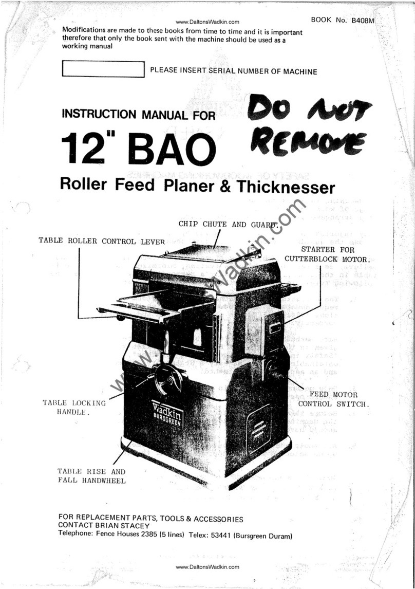
Wadkin bursgreen User manual

www.DaltonsWadkin.com

12"
HAND
FEED
PLANER
TYPE
12"
BFT
I.
..
PLANING..
TABLE
..
RISE.AND FALL.
HANDWHEEL. . .
PLANING.
TABLE
LOCK
SPECIFICATION
Planing
capacity
Length
of
tables
Speed
of
cutterblock
Cutting
circle
of
cutterblock
Fence
: Length
Height
Will
cant
to
Maximum depth of
rebate
in
any
widtlt
of.timber
Maximum de'tJth of
rebate
when
timber
overhanging
table
does
not
exceed
1"
(25mm)
Rise
and
faU
of
tables
H.
P.
of
driving
motor
:
3phase
Iphase
Syn.
speed
of
motor
Height
of
table
from
floor
Floor
space
.
Net
weight
Gross
weight
Sbipping
dimensions
.
12"
wide
72"
5, 000
rpm
4"
36"
4~tll
45.
0
5/8"
In
.!n
•
3
3
3,000rpm,50cycles
34"
72'"
x46
n
650
lb
7601b
53cu.ft.
STARTER
,300mm
1,.
830mm
5,OOOrpm
lOOmm
g.15mm
120mm
45°
16mm
25mm
19mm
3:
3:
3,
600rpm,
..
60;
cycles,
860mm
1
•.
630mm
x.
1,.
120mm
.
295 kg;.
,.
345
kg
1.5m3
"'.
i
,
www.DaltonsWadkin.com

2.
:rnSTALLATION
~RemoveproteGl:ive
coating
from
bright
parts
by
applying a
cloth
soaked
in
paraffin,
turpentine
or
other
sol
v€nt.
When
the
machine
is
cased
for
export
the
fence
andiront
cutterblock
guard
are
~r€movedandpack€d
individually.
Remove
and
re-assemble
as
shown
in
Fig.
1.
,
~
WIRING DETAILS
~The
motor
and
control
gear
have
been
wired
in
before
nespatch.
All
that
is
required
is
to
connect
the
power
supply
to
the
starter.
Points
to
note
whell,cq,lUl,ectingtopower
supply:-
1.Chec~1:fi~;~ltage~
phase
alldfr~quency\!orrespond
to
those
on
the
motor
plate,also~
the
correct
cogs
and
heaters
are
fitted
to
the
starter.
~
2.
It
is
important
that
the
carrect;cable
is
used
to
give
the
correct
voltage
to
the
start
eras
running
on
low
voltage')Vilr'l1amag€
the
motor.
3.
Check
the
main
line
fuses
are
Of
thecorrecicapacity.
See
Hst
below.
4.
Connect
the
line
leads
to
the
'appropriate
terminals.
See
Fig.
2
for
three
phase
~
supply.
See
Fig.
3
for
single
phase
supply.
5.
Check
all
connections
are
sound.
~
6.
Check
the
rotation
of
the
motor
for
the
'correct
direction.
If
this
is
incorrect
on ;
three
phase
supply
reverse
any two of
the
line
lead
connections.
i
VOLTAGE
220
330/420
550
200/220
230/250
!.
L1JBRICATION
PHASE
3
3
3
1
1
HP
,
'3
'3
3
'3
3
S.
W.G.TINNED
COPPER
WIRE
'21
22
23
17
~
17
FUSE RATING
AMPS
29
20
65
65
, .
It
is
advisable
to
keep
.all
bright
parts
covered
with a
thin
film
of
oil
to
prevent
;'
rusting.
See
Fig.
4.
The
&lideways
should
also
be
kept
clear
of
chippings
for.ease
of·
.
operation.
TYPE
OF
OIL RECOMMENDED
TYPE
OF
GREASE RECOMMENDED
1 FOUNDATION
POWER
EM
125
SHELL ALVANIA
3'
See
Fig.
5
for
bolt
positions
and
Clearance
required.
When
installing
the
machine,
.
l.evel
the
table
by
packing
under
the
feet.
Foundation
.bolts
are
not
supplied
with the'
machine
except
by
special
order.
1
BELT
TENSION
-',
The
drive
is
by:means
of 2
vee
belts
from
a BHP
motor
mounted
on
a
.hingebracket.
To
check
the
belt
tension,
remove
the
belt
guard
at
the
rear
of
the
machine.
The
tensioning
:arrangement
fs
shown
in
Fig.
6.
.'
Tore..;tension
the
belts
the
undermentioned
procedure
shouln
be
followed:-
,1.
Remove
the
cover
'''A''
in
Fig.
6
for
access
to
the
tensioning
nuts.
,2.
Adjust
nuts
''E''
~and
nc"
untii
the
correct
tension
is
reached
then
re-tighten
nuts
""E"
and
'nc
n • . . "
3.
R
"place
beUguard
and
cover.
4.
To
'ensure
trouble
free
running
of
the
machine
it
is
advisable
to
check
the
belt
tension
regularly.
www.DaltonsWadkin.com

M
o
T
o
R
cr--_
....
A
LIIIK
....---
ON
WIRING
DIAGRAM·
FOR
3 PHASE
SUPPLY
•
•
.
"\
•
•
•
M
A
. I
N
S
WIRING
DIAGRAM
FORI··
PHASE
SUPPLY
FIG
2~
FIG 3.
www.DaltonsWadkin.com

·
...
---
.......
----
..
-.--.
._---------_
.....•
_---.-----
...
--
...
-
OIL
aRIGHt
PARTS
UNDER
TABLE
wEEKLY
GREASE
MOTOR
AT
BOtH
ENDS 2
.....
TUANSPEA
YEAR
-+------,~"I-
-,
::
, '
/ \\1::
r + 1\:
11
~
.i
A
I,
11
"",
-
./
I::
JI
1\
4
lIT
..
)
11'
L
__
-
..:'.~_.J\\
~/
" /
''':::..'''!..
....
, ,
, ,
I , .
,-~.'"
LUBRICATION·
OIL
FENcE LINKS &
RACK
BAR
WEEKLV
FIG
04
•.
\
.'
www.DaltonsWadkin.com

I
' .
i
I
I
i·
FOUNDATION
t
46"
(1168
MM)
-,--------C-/
-'-------'-~.---'---_
-r-l
2-~6
DRILL
(14
MM)
.
.
-d
.
I'~
I-'
/
'\
, (
-
-I
--
-.,.,-
I
,,_
-:- _
"7
I I I
, , : 1
:h
28"---F==+----,·;----~:
: .
--+-'----,.--~""1:
(1)1--
(711.MM)
""""---t
+-
'I:
CNTS.
'1:
I 1 1 I
I I . , I
1 I : 1
./
.
,
17
"'''
(438
MM)
.
\ -I I
b:r---r::;k:±====:Jr------
.....
\
'.,.-
- - - - - - --r _
-_
-_
r=11::-~=-=-=-=-=;.-..,,::;:;'
.::/==:::::/~------t_-L-
L
I ,
I 1
-J~~~--~--~----~-----=-===Lii"
__________
~
____
~
________
~
.
(1~?9MM)
FIG
5.
PI
www.DaltonsWadkin.com

A
· FI<?6.
~--""---'.'"
,:-!-::."----~---.,;.---..,.".----------,.
---
SETTING
DEVICE
BACK
TABLE
CUTTE~BLADE
SPRING LOADED
H
4DJA
CUTTING
CIRCLE
TABLE
SKETCHSHOWlNG
KNIFE
SET
TING DEVICE
IN
POSITiON
FIG 7.
www.DaltonsWadkin.com

·C UTTER SETTING
7.
The
knives
are
held in
the
cutterblock
by a
steel
.clamping
bar
secured
with 5 -
t"
·
whit
heat
treated
sockethead
screws.
When
the
locking
screws
are
released
the
cutters
are
ejec!edslightly
by
lI:
small
leaf
spring.
This
is
to
facilitate
easy
cutter
setting
with
,
the
specIal
gauge supplied. As
the
amount
of
cutter
projection
is
vital
to:
the
correct
operation
of
the
machine
it
is
most
important
that
the
actual
gauge supplied with
the
"
machine
should
be
used. Should any
other
method of
cutter
setting
be
employed
the
amount of
cutter
prbjection
must
be
exactly
the
same
as. with
that
given
by
the
setting
gauge supplied and failure
to
observe
this
instruction
will result:
ille
poor
finish.
To
remove
the
cutters
and
re-set
with
''Bursgreen''
cutter
setting
gauge proceed: as. follows
:.-
1.'
Move
the
fence to
rear
of
the
table
and
lower both planing tables'.to-
their
lowest:
position.
2.
Turn
the
cutterblock
to approximately the position shown
in
Fig.,
7"
and
slacken
the
securing
screws
until
the
knife
is
just
free
of
the
cutterblock.
Care
shti'tilt\:Jle,
taken
when loosening
the
last
screw
as'
the
knives
are
spring
loaded. .
The
knives
can
now
be
removed
for
grinding
or
replacing.
When grinding
Itts:
most
important
that knives
are
ground
dead straight:
and
balanced
in.
pairs
or
sets
•.
An efficient
re-grinding
service
is. available.
Charges
are
moderate
and
service
prompt.
To
avail
yourself
with
this
service,
return
cutters
to:-
BURSGREEN(DURHAM) LIMITED
FENCE
HOUSES,.
HOUGH
TON
LE SPRING, CO. DURHAM.
3.
To
re-set
the knives,
the
cutterblock
should
be
in
approximately
the
position. shown
in
Fig. 7.
Place
the knife
in
the
slot
making
sure
that
all
faces
are
clean.and
the
clamping
bar.
free
from
burrs.
Press
the
knife into
the
cutterblock
with
the
setting
device
in
Fig. 7 until
the
four
predominant pads
rest
on
the
outer,
surface
of.
the
cutterblock
and
the
end
stop
plate
is
pressed
against
the
rebate
side
of
the
back
planing
table.
Position
theknifeJ;;o-
that
its'
end
butts
against
the
stop
plate
So·
as
to
line
up the
tip
of
the
knife
with.
tile
.
edge
of
the
back table.
4.
Holding
the
setting
device
securely
in
this
position, tighten
the
securing
screws.
Before
fully tightening
the
screws,
check
that
they
have.
not moved
ille
the
setting
process.
The cutting edge should
now
be
dead
parallel
to
the
planing
tables
and
the
edge
in
line
with
the
back
planing
table
edge.
Check
that
all
the securing'
screws
have
been
tightened
before
setting
the
next knife
..
5.
Rotate
the
cutterblockuntil
the
next
knife
is
in
position and
repeat
the
procedure
until
.
all
the
knives have
been
set.
6.
To check
the.
setting
of
the
knives
raise
the
back
table
to
its
top. position
i.
e.
the
zero
mark
on
the
rule
or
1/16"
above
the
outer
surface
ofthecutj:erblock.
Place
a
straight
edge on
the
table
as
shown
in
Fig. 8
and
rotatethecutterblockby
hand until
the
knife
just
touches
the
straight
edge.
Repeat
this
check
in
various
pOSitions
over
the
width of
the
table to
ensure
the
knife
is
parallel.
Repeat
this
procedure
for
all
knives.
7.
When changing
cutters'
it
is
advisable
to
check
that
all
the
locking screws:
are
adeqnately
lubricated
and
quite
free.
Periodically
examine
for
damage
or
cracks
particularly
in,
the
hexagon hole. Any doubtful
screws.
should.
be
replaced
and:
all
screws
well
lubricated
with "Molyslip"
or
similar
oil~
bllforereplacing.
CUTTER
CARE
_
The
cutters
supplied
are
12t"
(311mm) long x
It"
(32mm)
wide.
x 1/8" (3mm) thick
in
balanced
sets.
·They
should
be
kept
in
balanced
sets,
by
ensuring;
that
t~~
cutters
have
· equal
dimensions
after
grinding
and
that
the,
cutter
edge
is
straight.
and'parallel
to.
the
'back
edge.
For
general
work, knife
angles
for
soft
and
hard
woods
are
recommended
as
in
Fig~
9 (a) and (b).
'.
When a
very
fine finish
is
required
in
dry
soft and
hard
woods a
slight
front
bevel
is
.given
as
in
Fig.
9 (c)'and (d);
For
wet
or
green
timber
the
cutting
bevel
maybe
decreased
.
five
degrees,
but
the
front
b~velshould
not
be
given. .
www.DaltonsWadkin.com

I
j
I
'~TrHT
EDrG_E_
+---'-
__
\".---------.".
~
Ol""./",
'\
.•..
,;'~./
I
~.
/.;
.,-
. , 1
.
~~",
I
...
'C.
_
_______
)
------)
t',
'-~
I
...
~
I
..."",
I .
...
...
I ..y
l.,
_____
_
LL'
_---"---'---'---'-
_________________
--:-_--:F....;;1..,:cG_8_"--J
b.~-----------~-'-------___,
'P
~';
-'i'_
'i-;
I'
e
(
1
f I
.".
r
i
:1
-,I
A B
FOR
SOFT WOOD
FOR
HARD
WOOD
.
",cj2S
0
I(~,J·
--IJ
I"
ii
C
FOADRY
SOFT
WOOD
F1G
9.
www.DaltonsWadkin.com

9.
Keep
the
cutters
sharp
when
in
position
by
using
a fine
grade
oil
stone
dipped
in'
paraffin.
Allow
thestoneto
rest
lightlyand
flat
on
the
bevel
and
pass
over
the
cutter
with
a
.rotating
action
a few
times.
Give
about
two
strokes.
on
the
full
length
of
each
knife
on
the
face
side
to
remove
all
burrs.
from
the
cutting
edge.
Do not allow
a:
heel
greater
than
1/32"
wide
on
the
bevel
before
removing
and
re-grinding.
Whentheheelbecomestoo
wide
the
knives
may
heat
up'
or.have
a
hammering
effect
on
the
wood and
more
than
normal
power
will
be
required
to
runthe
cutterblock.
FENCE
ADJUSTMENT
The
fence
cants
by
means
of a
single
lever
"A"
in
Fig.
10
to
450•
The
angle
to which
.
the
fence
is
canted
is
shown on a
graduated
scale
"C"
•.
To
cant
the
fence
to
the
required
angl~
loosen
the
handwheel
"B"
and
lift
handle:
"A"
until
the
required
angle
is
shown
on
the
graduated
scale
"C",
then
re-Iockhandwheel
''B''.
The
fence
front
plate
is
fitted
with
an
insert
"G"which
is
over
the.
rear
planing
table
and
is
adjustable
depending on
the
depth of cut which
is
being
taken.
To
adjust
the
insert
loosen
the
wing nut
"D"
and move
the
insert
until
it
just
touches
the
rear
planing table·
then
re-lock
wing nut
"D".
The
insert
should
be
loosened
at
all
times
before
lowering
the
front
planing
table.
The
fence
is
also
adjustable
across
the
full width of
the
table
by means. of a
rack
and
pinion.
To
adjust
the
fence
across
the
table
loosen:
the
handwheel
"E",
and
turn
the
handwheel
"F"
in
the
direction
which
the
fence
is
required
to
move,
until
the
required
position
is
reached,
then
re-lock
handwheel"E".
The
fence
should
be
locked
in
both
positions
at
all
times
when
the
machine
is
in
operation.
. . 6
The
fence
has
positive
stops
at
90 .and 450•
These
are
both
accurately
set
before
despatch
from
the
works.
To
check
the
positive
stops
on
the
fence
the
undermentioned
procedure
should·
be
followed:-
1.
Move
the
fence
towards
the
rear
of
the
table
as
shown
in
Fig.
11. .
2.
Check
the
900
positive
stops
by
means
of a
steel
square
as
shown in.
Fig.
11.
If
adjustment
is
necessary,
adjust
the
hexagon
head
bolts
"A"
until
the
fence
is
at
right
angles
to
the
table
when .hard up
against
the
stops.
and
the
handwheel
"B",ln
Fig.
10 locked. .
3.
Check
the
450
positive
stop
by
means
of
an
adjustable
square.
If
~ustment
is
necessary,
adjust
the
.socket
head
grubscrew
liB"
until
the
fence
is, 45 to
the
table
when
hard
up
against
the
stop
and
the
handwheel ''B''
in
Fig.
10
locked.
4.
If
adjustment
is
necessary
to
the
positive
stops
check
that
the
graduated
scale·
is
still
correct.
This
is
secured
to
the
support
barby
means:
of
a
socket
head
grubscrew.
This
should
be
loosened
and
the
scale
accurately
positioned
to
the
pointer.
GENERAL HINTS FOR SURFACE PLANING
1.
To
obtain
the-best
surface.
finish
always
check
the.
direction
of
the
grain,
which
should
run
with
the
cutter
as
shown
in
Fig.
12.
2.
To
obtain
aperfectly
flat
surface
especially
with
warped
stock,
always
put
maximum
pressure
on
the
back
table
at
"A"
in
Fig. 13
and
as
little
as
possible
on:
the
front
table
at
"B
11
•
3.
Greater
pressure
will
be
required
when
surfacing
bad
grained.
timber,
otherwise
chattering
will
take
place
resulting
in
coarse
finish
near
each
knot.
4.
When planing
four
sides
of
timber,
square
turn
the
timber
anti.-clockwise
after
each
cut,
so
that
there
~ll
always
be
a
machined
face
next
to
the
fence
as
in
Fig.
14.
The
fence
locates
accurately
at
900•
.
11
I
I
I
www.DaltonsWadkin.com

I
i
~
.~
l'
I
I
I
11
I
l'
I
FIG
10.
8
j A
jL-
__
~~
______________________
~
__
~
__
~
__
~F_IG
__
I1~.~.
&ACK
TABLE
FEED
--
FRONT
TABLE
CORRECT RUN·
OF
. GRAIN
FIG
12.
------~--~~=-~
www.DaltonsWadkin.com

A
BACK
TABLE
FEED.
11(
E!L
-+-/---
+----+-
FEEDING
WARPED
TIMBER
B
FRONT
TABLE
FIG
13;.
~------':"----------------------'-.'.;
-"
FNCE
PLANED
SIDE
WORKING
WITH
FENCE
FIG
14.
www.DaltonsWadkin.com

SPARE
PARTS
LIST
FOR
12"
BFT
,
"OCyc1e
Machine
:<',1
:i
-Brook
Motor,
frame
M66B,
3HP,
2840
rpm,
foot mounted,
terminal
box
at
90'clock
lphase,50
"cycl-es.
j -
MEM
start-er
84ADS/FO
1 -
Cutterblock
pull-ey -
B-1036/13
"1 -
Motor
Pull-ey I -
B-I036/1-5
2 -
Fenner
V
belts
-
A-53
50Cyde
Machine
1
-Brook
Motor,
frame
M66B,
3HP,.3,-400rpm,
foot mounted,
terminalbox
at
90'clock
3phase,60cycles
.1 -
"Brook
Start-er
-AT3
1 -
Cutterblock
"pulley
-B-I03i3/13
.1-
Motor
Pulley
-
B':'1036/41
;2
-FennerV
belts
-
A-52
:
Single
Phase
Machine
,
.1 -
Brook
Motor,
frame
D-I00LB,
3HP,
2840rpm,
foot
mounted,
terminal
box
at
90'clock
"lphase
50cyc1es
:1 -"Brook
Starter
-ZVC
i1
-"
Cutt-exblock
pulley
-
B-I03i3/13
i1
-
Motor
Pull-ey -
B-1036/15
;:2
-F-enner V
belts
-
A-53
!BearingsUsed
;-
r
-(SKF)
88506
Ball
Rac-e
(Drive
Side)
J:o
6 0 I
fJ6f
-tkflk
P-
(Fischer)
DN205
Ball
Race
(Rebate
Side)
ko601'L~r-"
,
www.DaltonsWadkin.com

EXTRA EQUIPMENT
I
PLANER
KNIVES
12i"
(3Umm)
long H. S. S.
planer
knives
B.
V.
p.
49
in
pairs
or
sets
of
three.
,
POWER FEED UNIT
TYPE
BLG.8
The
feedunit
is
suppliedwith 3 independently
sprung
• .
rubber
tyred
feed
rollers,
two
speed
electric
motor
of
Q.
5/
Q.
7HP andincluding .reversingswitchgiving .
Sfeed
speed
of
6,13,16,19,33,39,49
& 99 feet
per
minute
(2,4,5,6,10,12,15
& 30
m/min)
REBATE TABLE
A
rebate
table
can
be
supplied
for
fittingto
the
front
planing
table
Standard
equipment
includes
universal
stand
for
horizontal
and
vertical
working,.
spanner
and
grease
gl,ln
..
Please state voltage
required.
www.DaltonsWadkin.com
Table of contents
Other Wadkin Planer manuals