Wagner & Co CIRCO 5 User manual

TECHNICAL INFORMATION / INSTALLATION MANUAL Wagner& C
o
CIRCO5SolarCirculationUnit
Fast Installation
through pre-mounted parts and
compression fittings for the
connection to the solar circuit
High Energy Efficiency
All around insulation and
speed controlled circulation pump
(in combination with all SUNGO solar controllers)
Controlled heat flow
by two temperature resistant
non return ball valves
Safe deaeration
by integrated air venting pipe
Variable Installation
wall mounting or fitted directly
to the storage cylinder
the reliable pump station for efficient
circulation of the heating fluid in
combination with SUNGO controls
CIRCO 5 Solar Circulation Unit
Function Control
through flow meter and
thermometers
Figure 1 CIRCO 5 solar circulation unit (SUNGO is an optional extra)
Solar Thermal / Solar Circuit EN-CIRCO-5-MA-0701-11217300 1

2EN-CIRCO-5-MA-0701-11217300
1. General Safety Guidelines
The following safety advice is deemed to protect against
dangers that can arise from improper handling of the de-
vice, whether knowingly or unknowingly.
We distinguish between general advice which is given on
this page and special advice which can be found in the texts
of the instructions. Watch for the symbols!
Qualification of the installer
Setting up, installation and commissioning of the CIRCO 5
solar circulation unit must be carried out by a qualified in-
staller.
Please note that in case of a fault report the guarantee ben-
efits can only be claimed if the correct commissioning has
been certified by a qualified person in the commissioning
protocol.
Use and application
Function
The CIRCO 5 solar circulation unit is suitable for solar hot
water systems and solar heating systems together with an-
tifreeze solar as recommended.
Limitations of use
●Use is limited to the hydraulic layout of the schematic
drawings supplied by Wagner and Co.
●Some solar installations for space heating and the appli-
cation of vacuum tube collectors do require special
means of overheating protection, like the installation of
an auxiliary vessel or alternative positioning of the safety
components.
●The CIRCO 5 solar circulation unit can be mounted to a
wall or directly to the storage cylinder.
●The CIRCO 5 solar circulation unit must not be mounted
outside.
Norms and guidelines
●EC conformity declaration
The CIRCO 5 solar circulation unit has been designed
and constructed in accordance with EU regulations.
●Please regard national and EU regulations and guide-
lines for installation work.
Danger to Persons
Live-threatening electrical shocks, burns, bruising and
other health hazards are possible during installation.
Please ensure that you pay attention to guidelines that are
indicated with this symbol in the documentation.
Caution Danger to Property
This symbol indicates that damage may be done to compo-
nents of the solar circuit or the function of the same may be
impaired seriously. Please make sure that you follow the in-
stallation procedure step by step as instructed.
Indicator for Additional Information
This symbol points to practical advice, tricks of the trade
which will make the installation and operation of the solar
circuit easier.

EN-CIRCO-5-MA-0701-11217300 3
2. Technical Information
List of parts supplied
The CIRCO 5 solar circulation unit is supplied pre-assem-
bled.
SUNGO control and CIRCO expansion kit are not part of
the unit.
You can find additional accessories on the last page.
Maximum number of collectors to be installed
Coll.-
Type
Serial-/Parallel connections * Serial connections
18 Ø 22 Ø 28 Ø 18 Ø 22 Ø 28 Ø
EURO 2 x 3 3 x 3 4 x 3 4 4 4
Parallel connections
LBM 67 4 5 6 1 2 2
LBM 100 2 3 4 1 2 2
* Number of fields each with 3 collectors connected in series
Table 1 Maximum number of collectors that can be installed depend-
ing on the collector type, way of connection and size of piping. Single
length of solar circuit up to 20m; heat carrier: frost protection/ water 40/
60 % per. Volume, Volume flow = 35l/m²/hConnection and connection
hoses at collectors are taken into account.
Size of expansion vessel
Fluid
litre
Coll.
area
m²
Vessel volume in litres
for system height in metres
2,5 5 7,5 10 12,5 15
18 5 121212121818
20 7,5 18 18 18 18 18 24
23 10 24 24 24 24 24 24
24 12,5 24 24 24 24 24 24
27 15 35 35 35 35 35 35
≥32 20 35 35 35 50 50 50
Table 2 Size of expansion vessel depending on the fluid content of the
entire system,collector area and height above vessel (distance vessel to
upper edge of collectors). Dimensioning scenario: system exposed to
full sun light but inactive. These values are only valid up to about 0.5
litres per m² collector volume.
00,5 1,5 2,0
0
0 1,0 2,0 3,0
[
m/h
]
3
[m/s]
H [m]
economy
1,0
6
7
5
4
2
1
3
v
maximum
Figure 2 Pump characteristics curves
CIRCO 5 solar circulation unit
Order No. 150 201 14
Insulation EPP (λ= 0.039 W/mK),
in three parts with snap-lock
Mounting plate Steel, galvanised
Max. operating pressure 6 bar
Max. operating temperature 120 °C
Circulation pump ST 25/6 (230V, 50 Hz)
Wattage 3 pump levels, 44/62/81 Watt
Max. pumping height 600 mbar
Max. pumping volume 3.5 m³/h
Controller Suitable for SUNGOS/SL/SXL
Non-return valves 2 x Heat-resistant metal
Temperature indicator 2 Integrated Thermometers
Flow meter Flow meter resistant to dirt
clotting
Safety unit Safety valve 6 bar DN 15 in
accordance with EN 12977,
manometer
Filler units 2 Filler and drain valves
with caps
Expansion vessel connection ¾" male
Security valve exhaust
connection
¾" female
Solar circuit connections Compression Fittings
18 and 22 mm
Centres distance of solar circuit
connections
125 mm
Installation options Suitable for wall and cylinder
installation (see accessories)
Dimensions (HxWxD) 420x260x190mm
Weight 6.7 kg
Figure 3 Front and side view, measurements in mm
420
190
184
60
125

4EN-CIRCO-5-MA-0701-11217300
3. Installation
3
4
5
1
4
4
2
67
10
11
3
9
8
12
13
14
15
16
D
spring clips
Figure 4 The parts of the CIRCO 5 solar circulation unit (numbering fits to numbers in brackets at description of assembling steps),
items with No. 7, 8, 9, 10, 12 and 14 are not part of the circulation unit.
ball valve with
integrated
thermometer
and non-return valve
air-release pipe
safety valve
compression
fitting
compression fitting mano-
meter
filler and
drain valve
circulation pump
flow meter with
filler and drain valve

EN-CIRCO-5-MA-0701-11217300 5
3.1 Installation Preparations
●The entire layout of flow and return pipes should be
clear before mounting the CIRCO 5 solar circulation unit
(125 mm centres)!
In this context please also observe the operation instruc-
tions "Commissioning the System"
●If the solar system is installed for heating or if vacuum
tubes are used you must pay attention to the technical
documentation “Heat Protection”.
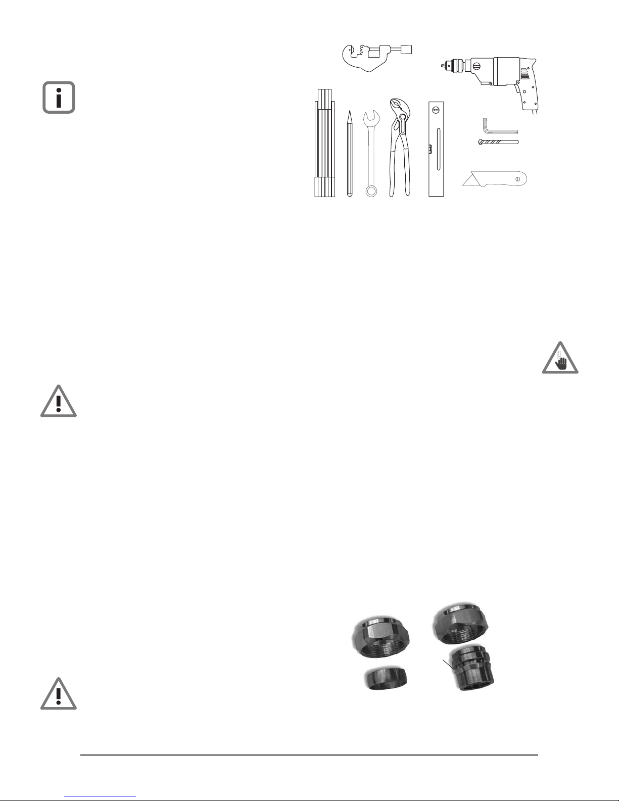
●These tools are required for the installation of the
CIRCO 5 solar circulation unit: Power drill, masonry bits,
pipe wrench, stilton etc. (figure 5).
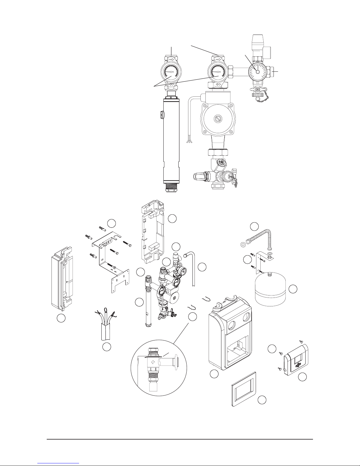
3.2 Wall Mounting
●Use spirit level to place the wall mounting bracket (1),
see figure 4, into the correct position, mark the three
holes, drill and fix with plugs and screws supplied.
●Place the two pieces of assembly (2+6) into the correct
holders of the wall mounting bracket and affix with the
two spring clips (3).
●Place the two halves of the back insulation (4) with the
recesses over the wall mounting bracket and push to-
gether.
●Connect the safety group (5) with the included ¾" gas-
ket to the free exit of the return unit (6) using an open
wrench SW30.
Make sure of proper clamping during the tightening of
the compression fittings to prevent damage or loosen-
ing of other parts of the assembly.
●Use the included wall anchors and screws to connect
wall-mount (7) for the expansion vessel (8) to the right of
the safety group. Observe length of the ¾" corrugated
tube (9). There are special wall mounting kits for 35 litre
and 50 litre vessels.
●Connect the flexible hose with the expansion vessel and
the pump station using supplied ¾ “ gaskets. It is recom-
mended to fit in a special cap check valve between flexi-
ble hose and vessel.
●Connect exhaust pipe (10) to the safety unit and put
empty container in place to collect any spills from the
pipe.
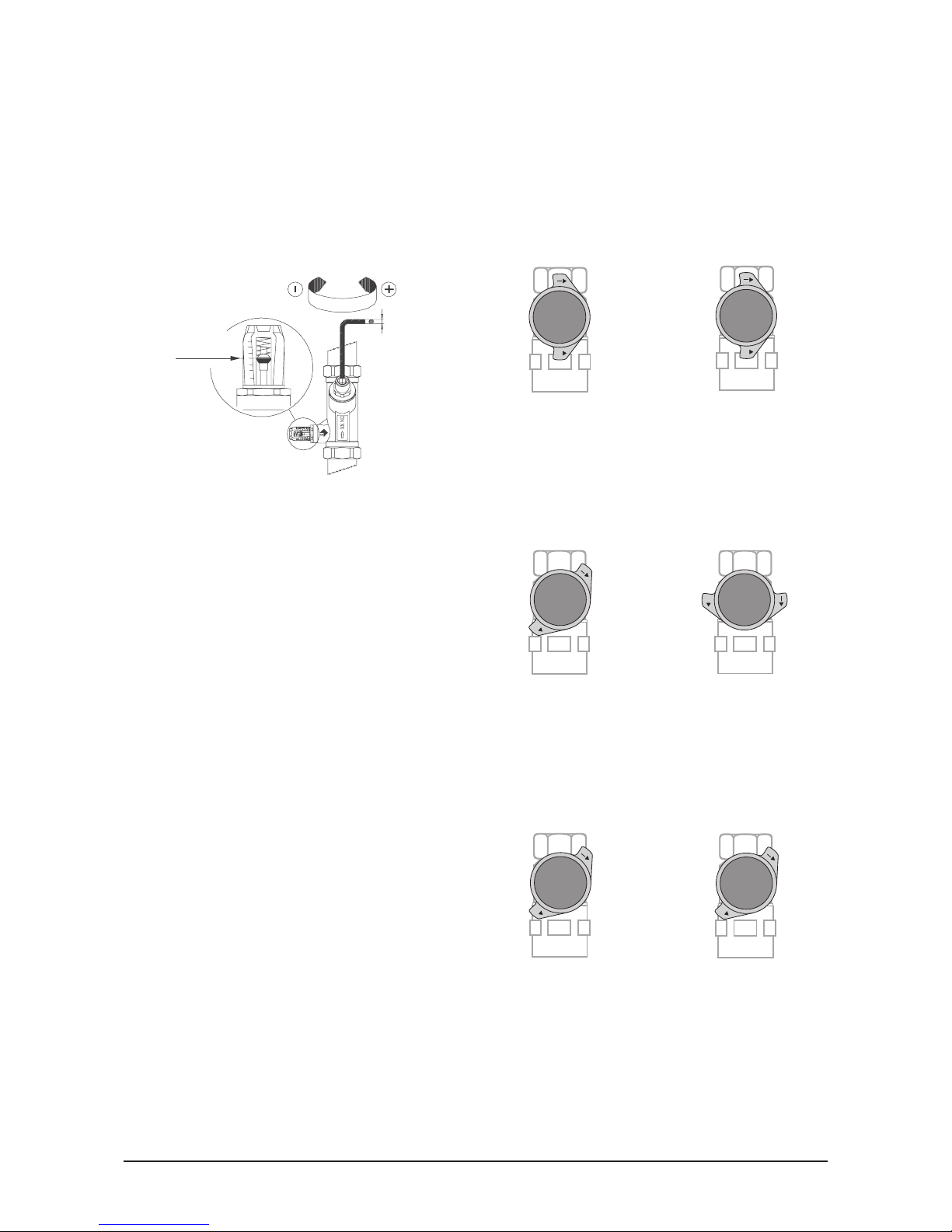
●The connections to the solar circuit (11) (distance of
pipes see figure 3) are made by compression fittings 18
or 22 mm (figure 6) .
Cut, burr pipes and push into fittings as far as possible,
then tighten nuts. Using the 18 mm compression fitting a
cracking sound will be heard, which is a sign of proper
tightening. Continue until fully tight.
Do not solder 18 mm compression fitting.
Here too, special care must be taken to ensure proper
clamping to prevent damage or loosening of other parts
of the assembly.
●Rinse solar pump station and solar circuit and check for
leaks. For this procedure a filler valve is fitted to the
safety unit (5) and the flow meter below the pump.
●Install electrical wiring, switching and sensor circuits
(12). Fix cables with cable ties to the prepared sections
(notches and long holes) to the wall mounting bracket
and ensure that there are no forces on the connectors of
the control unit and that there is no contact with hot pip-
ing. If required feeding holes can be enlarged with a
sharp knife.
Always disconnect mains when working with electrical
equipment!
●Remove frame (13) from the pump station in order to in-
stall the SUNGO control.
●Open SUNGO control (14) and affix with the four screws
(15) supplied to the wall mounting bracket. You will find
all required installation and operating instructions in the
manuals for SUNGO S, SUNGO SL and SUNGO SXL.
●Put front insulation (16) into place.
compression fitting
for 22 mm
compression fitting
for 18 mm
snapping
point
Figure 5 Tools required for the installation of the CIRCO 5 solar circula-
tion unit
Figure 6 Compression fittings 18 and 22mm

6EN-CIRCO-5-MA-0701-11217300
3.3 Mounting to Cylinder
The adjustable mounting kits can be used with all Wagner
solar cylinders with 1¼" flat tightening connections, if the
vertical distance of these is between 400 and 640 mm.
In order to prevent later obstructions of the pipe work in
the area of the cylinder it is necessary to make proper lay-
out plans before commencing.
●Connect pipes to cylinder using supplied gaskets.
●Adjust the height adjustment until both pipes are reach-
ing the same level and have a distance of 125mm.
Tighten adjustment nut.
●Trim off the insulation of the adjustable pipe and place
pump station on top.
●Level the unit and affix to the cylinder.
●Connect remaining pipe work.
In order to prevent forces to the cylinder fixing because of
pull from pipe work, pipe fixtures should be used at a near
wall or at the ceiling.
The expansion vessel must not be hung from the pump sta-
tion. Apply wall or floor mounting, depending on type of
vessel.
●Always ensure proper clamping when tightening 32, 41
and 46 mm nuts in order to prevent loosening of other
joints or damage to the unit.
Figure 7 The adjustable cylinder mounting kit consisting of:
Adjustable return pipe fitted with filler and drain valve, including insula-
tion and fittings: 1¼" nut and 22 mm sleeve for compression joint.
Flow pipe including insulation and fittings: 1¼" nut and 22 mm sleeve
for compression joint.
125
450 mm
suitable for 450 mm to 649 mm
D=22mmfor
compression fitting
adjustable pipe
fixing nut
filler and
drain valve
insulation
1¼“ nut

EN-CIRCO-5-MA-0701-11217300 7
4. Operating Advice
The Flow Meter
The flow meter indicates flow if the pump is switched on.
The exact value can be read from the display. It is possible
to adjust the flow by turning the adjustment screw with a
4mm Allen key during pump operation. If the screw is
turned fully clockwise, flow will stop completely.
Flow is cut off, when set screw is turned right to stop posi-
tion.
litre/minute
4mm
example
8 litre/minute
2
4
6
8
10
12
14
Figure 8 Flow meter of the CIRCO 5 solar circulation unit with adjust-
ment option
The Return-Flow Stoppers
When the circulation pumps are turned of, unwanted heat
distribution in the solar circuit is prevented by non-return
ball valves. They only open into the flow direction and by
pump pressure. The ball-valve handles can be used to turn
them off.
●During operation
●Filling the system
●Emptying the system
“Flow on”
Ball valve handle vertical
Non-return valve in operation
“Flow off”
Ball valve handle vertical
Non-return valve in operation
++
Figure 9 Operational position
“Flow on”
Ball valve handle 45°
Flow open, non-return valve off
“Flow off”
Ball valve handle horizonta
l
Flow closed
+
+
Figure 10 Filling the system
“Flow on”
Ball valve handle 45°
flow open, non-return valve off
“Flow off”
Ball valve handle 45°
Flow open, non-return valve off
+
+
Figure 11 Emptying the System

Subject to modifications, errors excepted. · © Wagner & Co, 2007 · www.wagner-solar.com
8WAGNER & CO · Zimmermannstraße 12 · D-35091 Cölbe/Marburg · ☎+49 6421 80 07-0 · Fax 80 07-22
5. Accessories
Accessories Description Order No.
Kit for solar circuit Accessories for the solar circuit pipe work:
2 filler and drain valves and 2 earth connector clips 190 210 22
Air release kit (not
normally required
because of included air
vent pipe)
Automatic air release kit
Consisting of 2 automatic air release valves and heat resistant ball valves
(up to 200° C), connection 3/8"
190 210 11
Manual air release set
Consisting of 2 Manual Air Release Valves 3/8" and Key 190 210 10
CIRCO –
expansion vessel kit Expansion vessel for the CIRCO 5 solar circulation unit, operating pressure max.
10 bar, stainless steel connection hose, connection ¾" female with gasket
12 l-volume, incl. wall mounting bracket, pre-pressurised: 1.5 bar
18 l-volume, incl. wall mounting bracket, pre-pressurised: 1.5 bar
24 l-volume, incl. wall mounting bracket, pre-pressurised: 1.5 bar
35 l-volume, with brackets for wall and floor fixing, pre-pressurised: 2.5 bar
150 300 70
150 300 77
150 300 98
150 300 99
Cap check valve for
expansion vessel
Check valve 3/4" with filler and drain valve and with cap against maloperation. 819 200 27
Cylinder mounting kit for
CIRCO 5
Non-adjustable pipe work 1¼" male flat tightening, insulated, adjustable return
pipe for cylinder connections with 400 to 640 mm vertical distance, with 22 mm
sleeves to connect to compression fittings of CIRCO 5
150 301 21
Table of contents
Other Wagner & Co Inverter manuals
Popular Inverter manuals by other brands

ECO-WORTHY
ECO-WORTHY 120W Foldable Solar Panel Charger user manual

Champion Global Power Equipment
Champion Global Power Equipment 200990 Operator's manual

SMA
SMA NR-STP-DC-CON-1012 Replacement manual

ATESS
ATESS HPS5000TLS user manual

Sofar
Sofar SOFAR 3K-6KTLM-G2 user manual

enphase
enphase IQ 7 Installation and operation manual

Haier
Haier 1U12BS3ERA Service manual

enertik
enertik GI TL series Installation and operator's manual

Xilinx
Xilinx Pico Blaze Frequency Generator owner's manual

Kaco
Kaco blueplanet 15.0 TL3 Operating instruction

Studer
Studer variotrack quick guide

Generac Portable Products
Generac Portable Products pp5000t owner's manual