Wagner & Co SECUSOL Manual

Solar thermal / Collectors EN-USA_SECUSOL_TI-MA-111013-1121R800 1
TECHNICAL INFORMATION / INSTALLATION INSTRUCTIONS
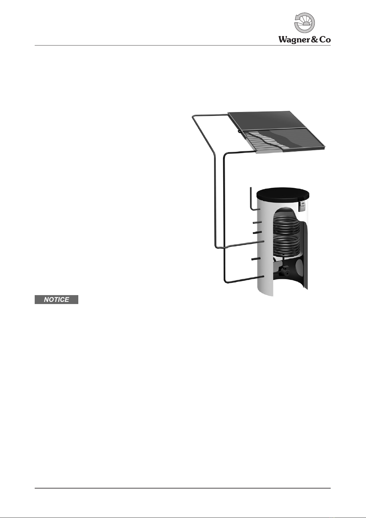
Compact Solar Drainback System SECUSOL
Figure 1 SECUSOL-System
Operational Safety and Low Maintenance
When the pump is not operating, there is no solar fluid
present in the collectors. Therefore the solar fluid and any
downstream system components are protected against
detrimental effects from overheat. Unwanted gravitational
forces as well as operational faults due to air pockets are
eliminated. A service intensive membrane expansion ves-
sel, air bleeds and check valves are not required. Operati-
on with common anti-freeze solar fluid prevents potential
frost damage.
High Yield Thanks To:
●High transparency anti reflection glass
●Single surface absorber with selective vacuum coating
●Solid insulation of individual components
Simplified Installation and Start-Up
●Pre-assembled unit of storage tank, solar controller and
solar circulator, including all safety components.
●Flexible copper double-pipe with only 12mm cross
section, for simple and time saving piping (supplied by
Wagner & Co).
●No expansion vessel and hence no setting of pre-pres-
sure required.
●Very simple flushing and filling
●No venting of solar circuit required
Installation, startup and maintenance of the SECUSOL
solar thermal installation are intended to be carried out
by trained professionals only, e.g. in line with SRCC Stan-
dard OG-300 installation guidelines or NABCEP certifica-
tion. They have to be licensed, must be familiar with the
IAPMO Uniform Solar Energy Code and must conform
to applicable federal, state and local regulations, codes,
standards and meet all legal requirements related to the
installation of solar hot water systems as well as plumbing,
electrical wiring and roof works.
Content
1 Technical Information 2
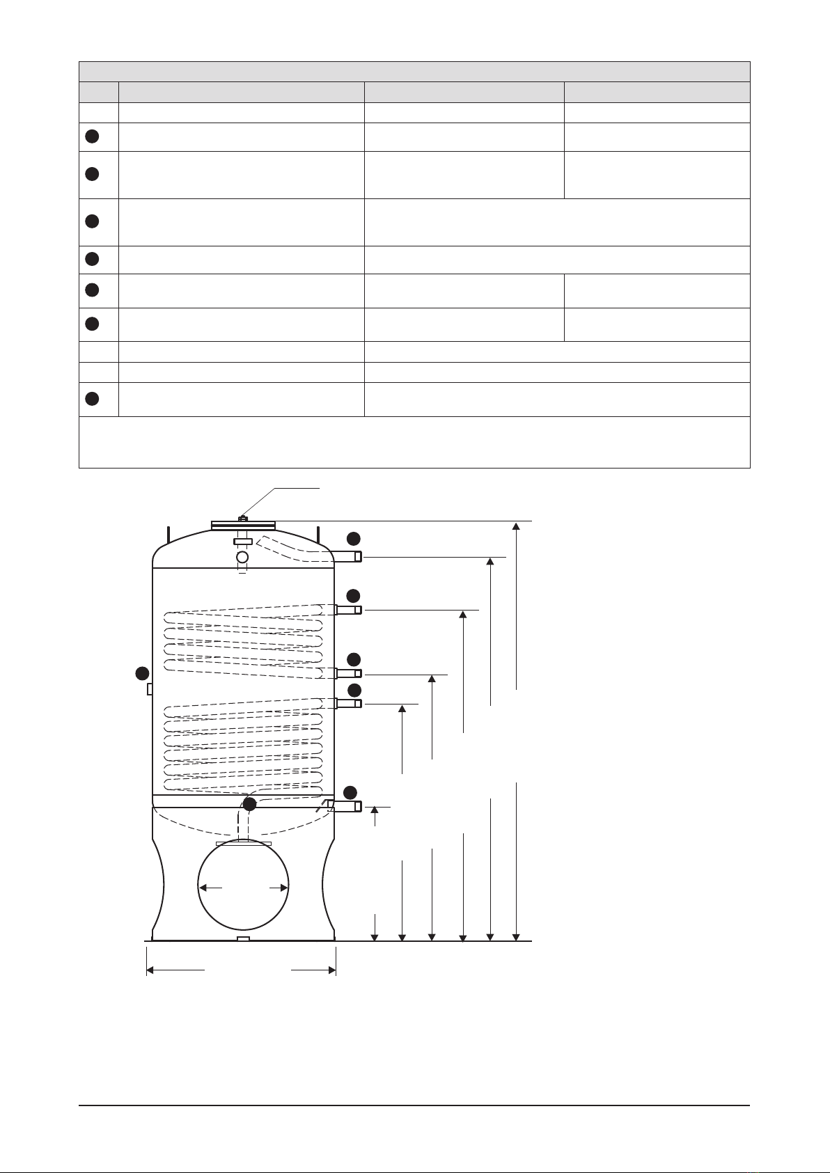
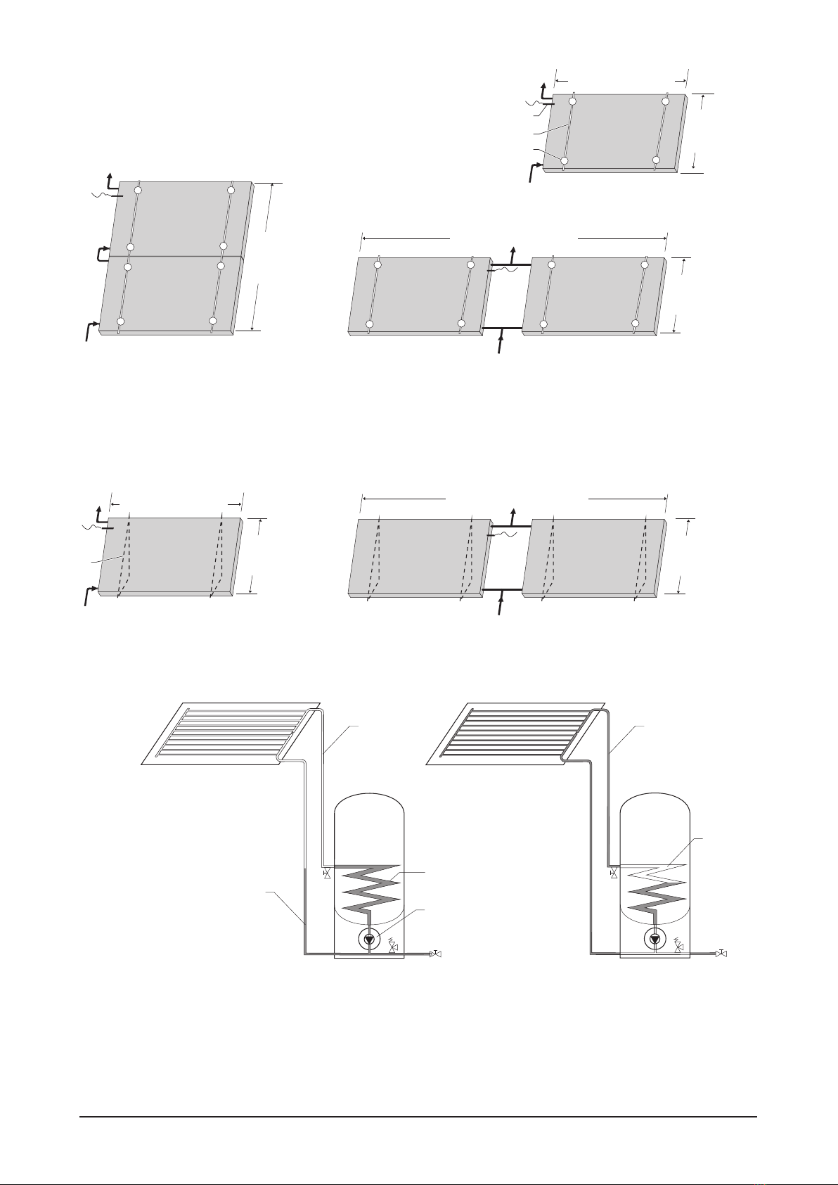
1.1 Technical Data 2
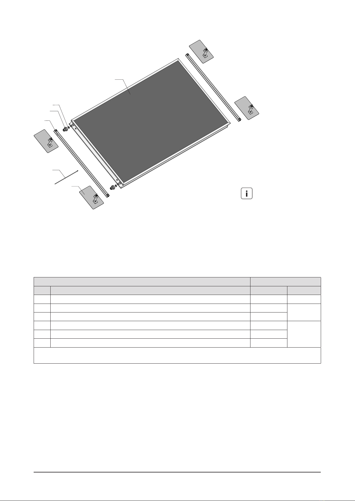
1.2 Scope of Supply 8
1.3 Accessories 14
2 General Safety Notes 16
2.1 Symbols 16
2.2 Standards and Codes 16
2.3 Qualification of the Installer 17
2.4 Intended Use and Application 17
2.5 Pre Installation Notes 18
2.6 Function of the SECUSOL system 18
3 Installation 19
3.1 Preparation 19
3.2 On-Roof Installation 20
3.3 Free Standing Installation 24
3.4 General Notes about Storage Installation 29
3.5 Setting up the Storage Tank 29
3.6 Connection to Domestic Water Supply 29
3.7 Laying the Solar Circuit 31
3.8 Installing the Controller 35
4 Startup 36
4.1 DHW System 36
4.2 Backup Heating Circuit 36
4.3 Solar Circuit 36
5 Connecting the storage Insulation 38
6 Advice for the User 38
7 Maintenance and Care 39
8 Troubleshooting 40

2 EN-USA_SECUSOL_TI-MA-111013-1121R800
1 Technical Information
1.1 Technical Data
Table 1 Technical Data
Features SECUSOL
250-1
SECUSOL
250-2
SECUSOL
350-2
Solar collectors
Type EURO C20 AR-M EURO L42 or EURO C20 AR-M
Gross area / aperture area sq ft (m²)
EURO C20 AR-M
28.1 sq ft (2.61 m²) /
25.7 sq ft (2.39 m²)
EURO L42
24.2 sq ft (2.25 m²) /
21.6 sq ft (2.01 m²
Collector racking On roof or free standing
Orientation of collector Horizontal installation only (pitch of 10° – 85°),
max. permitted diversion from horizontal orientation: 2°
No. of collectors 1 2 (cannot be extended)
Solar circuit
Collector circuit material (on site) Cu 12mm, order as needed from Wagner Solar, see material requirements in table8
Insulation material (accessory) see material requirements in table8
Length of solar circuit
(sum of flow and return legs)1Minimum 16.4 ft (5 m) / maximum 98.4 ft (30 m)
Maximum operating pressure 87 psi (6bar)
Installation height 2) Minimum 3.3 ft (1 m), from the bottom of the tank to the bottom of the collector
Maximum 28 ft (approx. 8.5 m), from the bottom of the tank to the top of the collector
Minimum temperature Frost resistant up to 1.4 °F (-17°C), if correctly filled 2)
Heat transfer fluid in
collector loop
Water/propylene glycol mix only with 33 % glycol 1) ,
filling capacity: 1.9 to 1.95 Gal (7.2-7.4 liters)
Solar controller
Name SUNGO US plus
Pump control Speed controlled
Overheat protection 180 °F temperature limitation for the tank
Storage
Nominal content 66 Gal (250 l) 92.2 Gal (350 l)
Stand by heating volume approx. 32 Gal (120 l) approx. 42 Gal (160 l)
Total height (including insulation) 62.83 in (1596 mm) 72.64 in (1845 mm)
Diameter (including insulation) 29.53 in (750 mm)
Permissible operation pressure /
Permissible operating temperature 145 psi / 203 °F (10 bar / 95 °C)
Corrosion protection
of the storage cylinder Enamel coating according to DIN4753T3
Cathodic corrosion protection Mg sacrificial anode acc. to DIN4753T6
Cold/hot water connections 1" NPT (M)
Sensor connection Clip in lower tank area
Solar heat exchanger approx. 12.39 sq ft (1.15 m²)
Backup heating coil none / approx. 6.0 sq ft (0.65 m²), depending on type approx. 8.61 sq ft (0.8) m²
Socket for electrical immersion heater,
Position: 1" NPSM (F)
Heat insulation
(PU foam, polystyrene jacket)
Cylinder and lid approx. 2.25 in (75 mm)
Base 1.57 in (40 mm)
Weight 285.5 lb (129.5 kg) 307.5 lb (139.5 kg)
1) See Figure 28 page31.
2) Lower edge of storage cylinder to lower edge of collector (Figure 28 page31).
3) In order to achieve higher frost protection, the glycol content needs to be increased to over 33 %. However, this results in increased
pressure drop and hence a reduced maximum installation height and length of solar circuit. Please also observe the technical
information of the solar liquid. If required feel free to contact our technical support.

EN-USA_SECUSOL_TI-MA-111013-1121R800 3
Figure 2 Dimensions of solar collectors EURO L42 (upper image) and EURO C20 AR-M (lower image).
40.78 in/1035 mm
76.10 in/1933 mm
45.79 in/1163 mm
EURO L42 HTF
3.15 in
80 mm
84.69 in/2151 mm
47.83 in/1215 mm
EURO C20 AR M
42.79 in/1087 mm 4.33 in
110 mm
Throughout this document and all other Wagner & Co do-
cumentation the term „flow“ refers to the hot, outgoing
pipe leg, while the term „return“ refers to the the colder,
incoming leg of the heating or solar circuit (the one retur-
ning to the heat generating device).

4 EN-USA_SECUSOL_TI-MA-111013-1121R800
Table 2 Storage dimensions in inch (mm)
Pos.1Dimension SECUSOL 250 SECUSOL 350
Total height (without insulation) 55.91 in (1420 mm) 70.75 in (1797 mm)
4
Socket (1"NPSM(F)), height above ground 34.13 in (867 mm) 44.72 in (1136 mm)
7
Hot water connection
(stainless steel and brass, 1NPT(M)) 2), height
above groand
51.3 in (1303 mm) 66.26 in (1683 mm)
2
Cold water connection
(stainless steel and brass, 1NPT(M))
2), height
above ground
18.78 in (477 mm)
3
Solar flow / hot side (G ¾) 2), height 32.17in (817 mm)
5
Backup heating flow / hot side2) (¾ NPTM(M)) 2),
height If present: 36.10 in (917 mm) 46.69 in (1186 mm)
6
Backup heating return (¾ NPTM(M)) 2) /colder
side, height If present: 44.37 in (1127 mm) 57.01 in (1448 mm)
Diameter (without insulation) 23.62 in (600 mm)
Base ring openings Ø 11.81 in (300 mm)
1
Solar return / colder side, pump flange height
above ground 13.8 in (350) mm
Legend:
1) Dimension position numbers from figures 3 and 4
2) Pipe thread DIN ISO 228-1 (cyl.), flat sealing
Figure 3 Dimensions SECUSOL 250 solar storage tank; (1) Flange with sacrificial anode; Dimensions of cylinders are without insulation.
SECUSOL 250 is available with and without backup heat exchanger (upper coil). The image shows the version with upper coil. The version
without upper coil does not feature the connections 5 and 6.
SECUSOL 250
1
1
2
3
5
6
7
1" NPT(M)
1" NPT(M)
3/4" G
1" NPSM (F)
3/4" NPT(M)
3/4" NPT(M)
3/4" NPT(F)
4
11.81 in
300 mm
18.78 in (477 mm)
32.17in (817 mm)
36.10 in (917 mm)
44.37 in (1127 mm)
51.3 in (1303 mm)
55.91 in (1420 mm)
23.62 in (600 mm)

EN-USA_SECUSOL_TI-MA-111013-1121R800 5
Figure 4 Dimensions of SECUSOL 350 solar cylinder (without insulation).
(1) Flange with sacrificial anode
1
SECUSOL 350
1
2
3
4
5
6
7
3/4" G
1" NPT(M)
1" NPT(M)
1" NPSM (F)
3/4" NPT(M)
3/4" NPT(M)
3/4" NPT(F)
11.81 in
300 mm
18.78 in (477 mm)
32.17in (817 mm)
46.69 in (1186)
43.54 in / 1106 mm
57.01 in (1448 mm)
66.26 in (1683 mm)
70.75 in (1797 mm)
23.62 in (600 mm)

6 EN-USA_SECUSOL_TI-MA-111013-1121R800
Figure 5 Connection options for the EURO L42 for on-roof and free-standing installation, with sensor positions, dimensions of the collector
field and racking system. The absorber connections can point to the left or to the right. (1) Solar sensor; (2) Rail; (3) Rafter bracket or roof
anchor; (4) Racking triangle.
On roof
Free standing setup
EURO L42
1
2
3
4EURO L42
76.1 in / 1933 mm
76.1 in / 1933 mm
>160 in / 4060 mm
91.57 in
2326 mm
45.79 in
1163mm
45.79 in
1163mm
45.79 in
1163mm
45.79 in
1163mm
>160 in / 4060 mm

EN-USA_SECUSOL_TI-MA-111013-1121R800 7
On roof
Free standing setup
EURO C20 AR-M
1
2
3
4EURO C20 AR-M
84.69 in / 2151 mm
84.69 in / 2151 mm
>177.17 in / 4500 mm
95.79 in
2433 mm
47.83 in
1215mm
47.83 in
1215mm
47.83 in
1215mm
47.83 in
1215mm
>177.17 in / 4500 mm
Figure 6 Connection options for the EURO C20 AR-M for on-roof and free-standing installation, with sensor positions, dimensions of the
collector field and racking system. The absorber connections can point to the left or to the right. (1) Solar sensor; (2) Rail; (3) Rafter bracket or
roof anchor; (4) Racking triangle
Figure 7 Design principle of the SECUSOL system. Left hand side: When in idle state, the collector loop and the collctor are filled with air
(light-coloured lines). The solar fluid (darker lines) is located in the heat exchanger. Right hand side: When the system is in operation the air is
pushed into the upper loops of the heat exchanger by the rising solar fluid.
System air
System air
Collector
Solar liquid
Solar liquid
System idle System in operation
Storage Storage
Heat exchanger
Pump

8 EN-USA_SECUSOL_TI-MA-111013-1121R800
1.2 Scope of Supply
The complete system is delivered with the following com-
ponents:
Table 3 Components Qty.
Collector EURO L42 1 or 2
Collector EURO C20 AR-M 1 or 2
Solar storage, nominal content 250 l or 350 l,
respectively (screwed onto pallet), incl. solar flow
and return group with circulator and solar
controller SUNGO US plus 1)
1
1 plug 1" NPSM (fixed to pallet), for closing the
storage socket 1
1) For details see Table 5 and Figure 8
Table 4 Scope of Supply System with
Boxed components 1 coll.
2 coll.
side
by
side
2 coll.
one
above
the
other
Customer information folder with
instructions and system
documentation
1
Solar liquid DC20 F 2.5 l in 5 l
canisters 1
Collector adapter set 1
US Secusol serial connection set 1
US Secusol parallel connection set 1
Roof anchor / rafter bracket (only for
on-roof installation)1) 4 8 8
1) Minimum no., actual no. depends on structural and geographical
situation.
Table 5 Scope of supply, storage SECUSOL 250 / SECUSOL 350
Position 1) Components Quantity
1 Jacket insulation 1
2 Cover insulation 1
3 Ground insulation 1
4 Storage cylinder lid 1
5 Solar controller 1
6 Container 1
7 Socket cover with integrated protective anode 1
8 Solar return subassembly 1
9 Ventilation opening 1
10 Plug 1" NPSM 1
Compression olive fitting 12mm 2
13 Storage cylinder connection nozzle 5
f Collector sensor 1
k Collector sensor cable 1
n Mains cable 1
p Pump cable 1
s Storage cylinder temperature sensor 1
1) Position numbers from Figure 8.

EN-USA_SECUSOL_TI-MA-111013-1121R800 9
Figure 8 Scope of supply of the SECUSOL storage cylinder shown for the 250 l- (see table 5 for a position number legend).
s
n
k
7
2
4
5
p
6
8
9
10
3
1
13
f

10 EN-USA_SECUSOL_TI-MA-111013-1121R800
Note
The roof brackets shown throughout
this document are of the type A1 Pro+,
specifically developed for common
North-American asphalt shingle roofs.
For installation details refer to the
separate instructions coming with the
roof brackets. Other roofing types
require different roof anchors.
Set for single collector
Table 6 On roof racking, set for single collector, scope of supply Single collector
Pos. 1) Components Quantity Part no.
1 Rafter bracket or roof anchor (recommended)²)(4)
2 Collector rail 49.5 in / 1257 mm (EURO C20 AR-M) with two collector clamps 2 192 001 00
3 wire strip 1
4 Collector EURO C20 AR-M 1
192 040 625 Compression olive connection ½" - 12 mm 2
6 Gasket ½" 2
1) Position no. from Figure 10
2) Not included in the set, to be ordered separately
Figure 9 Single basic set for on-roof installation with collector
EURO C20 AR-M
3
2
1
4
5
6

EN-USA_SECUSOL_TI-MA-111013-1121R800 11
11 EN-USA_SECUSOL_TI-MA-111013-1121R800
Table 7 On roof racking, set of collectors installed one above the other, scope of supply Part no.
Pos.
1) Components Quantity for EURO C20 for EURO L42
1 Rafter bracket or roof anchor (recommended)²)(8)
2Collector rail 49.5 in / 1257 mm (EURO C20 AR-M) or 47.32 in / 1202 mm (EURO L42),
respectively, with two collector clamps 2
192 000 98 192 001 02
3Collector rail 48.2 / 1223 mm (EURO C20 AR-M) or 45.98 in / 1168 mm (EURO L42)
with one collector clamp 2
4 Rail connector 2
5 Wire strap 1
6 Collector EURO C20 AR-M or L42 2
7 Collector interconnection hose with insulation pieces and flat seals 1
192 040 64
8 Compression olive connection ½" - 12 mm 2
9 Gasket ½" 4
1) Position no. from Figure 10
2) Not included in the set, to be ordered separately
Figure 10 Set for on-roof installation of 2 collectors installed one
above the other
Note
The roof brackets shown throughout
this document are of the type A1 Pro+,
specifically developed for common
North-American asphalt shingle roofs.
For installation details refer to the
separate instructions coming with the
roof brackets. Other roofing types
require different roof anchors.
1
2
4
3
5
8
9
6
7
Collector installation set for horizontal installation, one
above the other

12 EN-USA_SECUSOL_TI-MA-111013-1121R800
Collector installation set for horizontal installation, next
to each other
Table 8 On roof racking, set of collectors installed next to each other, scope of supply Part no.
Pos.
1) Components Quantity For EURO C20 For EURO L42
1 Rafter bracket or roof anchor (recommended)²)(8)
2Collector rail 49.5 in / 1257 mm (EURO C20 AR-M) or 47.32 in / 1202 mm (EURO
L42), respectively, with two collector clamps 4192 000 99 192 001 03
3 Wire strap 1
4 Collector EURO C20 AR-M or EURO L42 2
5 Compression olive connection ½" - 12 mm 4
150 303 93
6 Gasket ½" 4
7 Compression T-fitting 12 mm 2
8 Copper tube 12 mm 4
9 Foam insulation 4
1) Position no. from Figure 11
2) Not included in the set, to be ordered separately
1
3
2
9
8
4
5
6
7
Figure 11 Set for installation of 2 collectors next to each other
Note
The roof brackets shown throughout
this document are of the type A1 Pro+,
specifically developed for common
North-American asphalt shingle roofs.
For installation details refer to the
separate instructions coming with the
roof brackets. Other roofing types
require different roof anchors.

EN-USA_SECUSOL_TI-MA-111013-1121R800 13
45
7
6
3
2
1
8
Table 9 Free standing racks, scope of supply Single collector;
order no. 192 001 00
2 Collectors next to each other;
order 2 x no. 192 001 00
Position 1) Components Quantity
1 Pre-assembled racking triangle 2 4
2 Hexagonal head screw M8 x 40 2 4
3 Nut M8 with locking teeth 2 4
4 Collector clamp – lower part 4 8
5 Collector clamp – upper part 4 8
6 Washer Ø 8.4 mm 4 8
7 Hexagonal head screw M8 x 30 4 8
8 Collector EURO C20 AR-M or EURO L42 2) 1 2
1) Position numbers from Figure 12.
2) Not included in the set
Figure 12 Set for free standing setup
Set for free standing rackets

14 EN-USA_SECUSOL_TI-MA-111013-1121R800
1.3 Accessories
Table 10 Accessories Description Part no.
Euro collector carrying handles (2 pieces) 192 040 60
Thermostatic Mixing Valve ¾" 150 303 83
Twin Cu solar circuit pipe comprised of insulated double copper pipe
2 × 12 mm with integrated temperature sensor line, 15 m coil 150 300 67
Oval clamp set for for Twin-Cu 150 301 18
Solar circuit insulation: flexible foam insulation 13x12 for single pipes (Aeroflex),
6.56 ft / 2 m length, 170 000 38
Flange cover gasket 139 001 15
Magnesium sacrificial anode 130 101 28
Temperature sensor Pt 1000 150 102 49
Storage cylinder height adjustment (always order 3!) 139 000 16
Earthing clamps (order 2!) 120 100 12
US Sensor connection box SP10 150 400 60

EN-USA_SECUSOL_TI-MA-111013-1121R800 15
Table 10 Accessories Description Part no.
US Secusol parallel connection set 150 303 93
US Secusol serial connection set 192 040 64
Collector adapter set 1/2“-12mm 192 040 62
US_Secusol Cx-threaded elbow connection set 12mm 819 110 99
4 x straight compression fitting 12mm 819 111 00

16 EN-USA_SECUSOL_TI-MA-111013-1121R800
2 General Safety Notes
2.1 Symbols
The following symbols are used throughout these inst-
ructions and must be adhered to. READ ALL INSTRUC-
TIONS CAREFULLY BEFORE BEGINNING INSTALLATION
WORK:
Immediate DANGER of serious personal injury, including
risk of death and lifelong disability.
WARNING against situations leading to possibly severe
injuries and death.
CAUTION against situations leading to minor injury and
material damage.
NOTICE of situations which may lead to property dama-
ge if no precaution is taken.
Notes with additional important or useful information.
2.2 Standards and Codes
Building and plumbing permits and/or inspections may
be required for installation. Comply with all code require-
ments and applicable standards and regulations.
Snow and wind loads - risk of injury from falling objects
or collapsing structures
Comply with federal, state, county and city regulations
and standards related to snow and wind load as well as
structural planning in general. Only install the installation
set on roofs that can structurally support the additonal
load. In case of doubt, always consult a structural engi-
neer or a roofer. Follow the Solar Rating and Certification
Organisation SRCC OG 300 guidelines for safe collector
installation.
Work on roofs - risk of fall and falling objects resulting in
potentially serious injury and death
We strongly recommend to follow the NAHB-OSHA Job-
site Safety Handbook, especially:
1. Inspect for and remove frost and other slipping hazards
before getting onto roof surfaces.
2. Cover and secure all skylights and openings, or install
guardrails to keep workers from falling through the
openings.
3. When the roof pitch is over 4:12 and up to 6:12, install
slide guards along the roof eave after the first 3 rows
of roofing material.
4. When the pitch exceeds a 6:12 pitch, install slide gu-
ards along the roof eave
5. Use a safety harness system with a solid anchor point
on steep roofs with a pitch greater than 8:12 or if the
ground-to-eave height exceeds 25 feet.
6. Stop all operations on roofs when storms, high winds
or other adverse weather conditions create unsafe con-
ditions.
7. Remove or properly guard any impalement hazards.
8. Wear shoes with slip-resistant soles.
Make sure to observe all federal, state, county and city re-
gulations related to roof works and roof sealing standards
as well as professional codes for plumbing work.
Installers must be qualified and - where applicable - li-
censed to work on roofs.
Risk of injury and material damage resulting from impro-
per handling of collector and storage
Use soft crane straps for lifting collectors with crane (ob-
serve secure overhead transport!). Alternatively loop
rope around the frame and pull collector up a secured
ladder. We also recommend the use of two ladders and
our special collector handles. Never attach ropes to coll-
ector connections and never use connection pipes as
handles! Only use the crane hoisting lugs on top of the
storage tank for crane transport. Observe good practice
standards for construction sites. Object is heavy and can
cause severe injuries and damage upon falling.
Uniform Solar Energy Code
The installation has to be carried out by a licensed pro-
fessional in accordance with all professional standards, in
particular all safety, health and environmental standards,
as given by the IAPMO Uniform Solar Energy Code. For
detailed information and to obtain the full text of the code
contact IAPMO:
International Association of Plumbing and Mechanical
Officials
5001 E. Philadelphia Street
Ontario, CA 91761-2816 USA
www.iapmo.org
System Integration
During integration of the storage tank into the domestic
water supply and connection of the solar controller, all
national and local health and safety regulations must be
complied with, including relevant lightning protection
regulations. When installing a backup heating device
please follow the manufacturer‘s guidelines. Follow the
Uniform Solar Energy Code.

EN-USA_SECUSOL_TI-MA-111013-1121R800 17
Conformity
The SECUSOL solar energy system and its components
were designed and manufactured in accordance with cur-
rent European Union and United States laws and regula-
tions. The system and its components are in compliance
with SRCC OG 100, IAPMO and NSF testing and/or certi-
fication standards, where applicable.
EN806-1 and prEN1717:1999
Provided the system is installed correctly, the require-
ments of EN806-1 and prEN 1717:1999 are met.
EN12976 and EN12977
The entire system was designed and manufactured accor-
ding to the regulations in EN12976 and EN12977.
2.3 Qualification of the Installer
Risk of injuries resulting from insufficient qualification
Setup, installation and commissioning of the SECUSOL
compact solar heating system must be carried out by au-
thorized professionals (e.g. NABCEP or Wagner Academy
certified or equivalent combination of knowledge and ex-
perience). The installation should be carried out following
the guidelines established by the Solar Rating & Certifica-
tion Corporation (SRCC).
See SRCC OG 300: SOLAR WATER HEATING SYSTEM DE-
SIGN AND INSTALLATION GUIDELINES, available on the
SRCC website at www.solar-rating.org.
Please note that in case of a warranty complaint the war-
ranty is only valid if the correct start-up has been certified
in a commissioning report. Contact us for further infor-
mation.
2.4 Intended Use and Application
Collectors should be stored inside in a dry place. Out-
door storage can result in damage.
For proper outdoor storage, remove PE film, and lay down
collectors with glass pane up. Avoid direct ground con-
tact (e.g. underlay square timber). Avoid scratches on
glass panes by using spacers between collectors (e.g.
wooden laths). When leaning collectors against walls or
similar, use a minimum inclination of 15° and apply spa-
cers. Do not use cardboard as underliner. If incorrectly
stored, humidity can enter the collectors through the air
vents. Storing collectors in foil package can damage the
glass surface (Figure 13).
Collectors: Scope and limitations of application
The collector is intended for the application in solar ther-
mal installations for hot water preparation and space hea-
ting support. ANY OTHER TYPE OF APPLICATION IS NOT
PERMITTED unless explicitly permitted in writing by the
manufacturer. Non compliance can lead to serious da-
Figure 13 Do not expose PE-film covered collector to rain
mage, health risks and renders all warranty void. As ope-
rating mediums water (attention – risk of freezing!) or an
appropriate water-glycol mixture can be used in a closed
circuit. Prolonged operation of the collector at conditions
below the dew point temperature within the collector is
not permitted! This can occur, for example, when collec-
tors are integrated in the brine circuit of a heat pump.
Preventing frost damage
After pressure testing and flushing, collectors cannot
always be completely emptied. Make sure that no pure
water remains in collector during risk of frost!
Unfilled collector on roof
After being installed on the roof, unfilled collectors
should not be exposed to the sun for more than a few
days. Otherwise thermal stress on gaskets can result in da-
mage. Alternatively postpone the installation of gaskets
to just before filling the solar circuit.
Maintenance only by trained professionals!
Under normal operating conditions we recommend an-
nual check and maintenance intervals. All testing, repair
and maintenance work must be carried out by qualified
and licensed professionals. For maintenance notes and
additional information about setup and operation of the
collector field, please refer to the technical information
“Solar Thermal Systems - Setup, Commissioning and
Maintenance”.

18 EN-USA_SECUSOL_TI-MA-111013-1121R800
2.5 Pre Installation Notes
Risk of burns at collector connections!
Collector connections can get very hot as soon as un-
covered collector is exposed to the sun (figure 3). Wear
gloves!
Danger of open injuries!
Always wear gloves to avoid severe cuts and lacerations
when working with sharp edged metal sheets and com-
ponents!
Risk of damage to absorber!
Remove protective plastic caps from connections before
collector is exposed to the sun. Risk of molten plastic
entering and damaging the absorber!
Risk of suffocation!
Remove glass protection PE-LD film before commencing
installation work! (Figure 14) Keep plastic film out of
reach of children!
2.6 Function of the SECUSOL system
Function
The SECUSOL solar thermal system is designed for dome-
stic hot water (DHW) preparation.
The solar fluid is pumped from the solar heat exchanger
to the solar collector where it is heated. The thermal ener-
gy carried by the solar fluid is then transferred to the do-
mestic water in the storage tank.
Backup heating of domestic water in the up-
per part of the storage tank can be done via a suitable
downstream continuous flow heater, an optional electrical
immersion heater or via the integrated backup heating
coil (not with SECUSOL 250 monovalent, i.e. only one heat
exchanger), when connected to central heating.
The included SUNGO US plus solar controller con-
trols the circulation pump speed depending on the tem-
perature difference between collector and storage. It also
monitors the max. storage temperature.
If the system is in stagnation, the entire solar flu-
id is moved to the heat exchanger, while collector field
and collector circuit are filled with system air (figure7, left
hand side). When the circulation pump is switched on, the
collector and the collector circuit are filled with solar fluid
and the system air is pushed into the upper coils of the
heat exchanger (figure7, right hand side).
Once the storage tank is heated up to the maxi-
mum temperature, the controller switches off the circu-
lation pump. Normally the solar fluid automatically flows
back to the heat exchanger. Otherwise if irradiation con-
tinues, the solar fluid vaporizes in the collector field and
the system is emptied this way. As the fluid retreats, the air
within the system flows into the collectors which quickly
reach their stagnation temperature. The heat transport to
the tank stops and the solar fluid, which is temperature-
sensitive, then is safely stored in the storage tank area.
Using a solar fluid with 33 % glycol content ensures per-
manent protection against frost damage, in addition to
corrosion protection.
By design heat loss from the storage tank due to over-
night convective recirculation or thermosyphonic flows
are impossible. Thus the installation of check valves is
not required. The installation of venting equipment and
a service-intensive membrane expansion vessel are un-
necessary due to the special 2-phase operating system.
Operational Limits
Note that the storage tank and solar controller must not
be installed outdoors and that the system may only be
operated within the permitted operating conditions
(Chapter1: Technical Information).
Due to the special system design a maximum of 2 collec-
tors can be integrated. Retroactive extension of the coll-
ector area is not possible.
The maximum system height is 28 ft / 8.5 m, the maximum
length of the solar circuit is 98 ft / 30 m (sum of flow and
return legs, according to (Figure 28 page31).
Other Documents that have to be Observed
The following documents must be observed during instal-
lation and operation:
Figure 14 Remove glass protection film before installing collector!

EN-USA_SECUSOL_TI-MA-111013-1121R800 19
●Operation instructions of the respective solar Control-
ler SUNGO US plus.
●Technical information „Solar Liquid DC20 F “, the re-
spective material safety data sheet and label on the
canister.
●Technical information of the respective collectors
Material Specifications
Table 11 Material specifications
Component Parameters Requirements
Solar circuit
piping
Material Copper only
Dimension 0.47 in / 12 mm Cu
Pipe insulation
Outside UV-resistant
Inside No special requirements
Temperature
resistance
Up to 347 °F /175 °C for a
short time
Dimensions and measurements
Dimensions usually are indicated in both: metric and US
customary units. In case of doubt the metric dimensions
must be considered more precise. The required screws
are included in the package and conform to ISO metric
standards. For some of the components included in the
delivery no exact US pendants exist. In these cases only
metric dimensions are indicated.
3 Installation
3.1 Preparation
Scope of Supply
Before commencing the installation, please ensure that all
components listed in table3 and 4 are present.
Material Required on Site
In order to complete the installation and commissioning
of the SECUSOL solar energy system, the following is re-
quired on site:
●Piping (copper pipe Cu12) for the collector loop pipes
●Insulation material for the collector loop pipes (for out-
side use, UV-resistant), available as accessory
●Electric extension cable for the collector sensors
(2threads with cross section of 18/2 AWG.)
●Thermostatic DHW mixer, available as accessory
●Storage cylinder safety subassembly for cold water
connection, available as an accessory,
For reasons of corrosion protection the collector loop
must be made of materials meeting the requirements of
table8. Other materials are not permitted. Suitable con-
necting methods are soldering, press fittings or clamp
ring connectors.
When installing the flat sealing connections please only
use the original soft fiber sealants included in the deli-
very. These sealants have been specially tested for this
purpose.
Required Tools
The following tools are required for the installation and
fixing of the collector loop system:
●Combined wrench 13 mm / 1/2 inch (for hexagonal
screw M8)
●Combined wrench 17 mm / 11/16 inch (for hexagonal
screw M10)
●Pipe wrench
●3/4" open-end ratcheting wrench (for collector con-
nection)
●Electric power screw driver with star bit (e.g. TorxTM)
set (for roof bracket fixation)
●2 water hoses of 2m / 6.56 ft length each, both with ½"
hose connector on one side
●Water bucket with a minimum capacity of 2.64 gal / 10li-
ters
Safety Note
Before installing the collectors, please read the informa-
tion leaflet “Safety Precautions for the Installation of Coll-
ectors”. Observe local statutory accident regulations as
well as the technical installation rules described in these
instructions.
The SECUSOL system is suitable for on-roof and free stan-
ding installation. The collectors have to be mounted ho-
rizontally to allow them to empty in idle state and during
stagnation.

20 EN-USA_SECUSOL_TI-MA-111013-1121R800
Figure 15 Correct fixing of roof bracket type A1 Pro+ on rafter
3.2 On-Roof Installation
The on-roof racking system allows fast installation of the
collectors on a pitched roof without having to open larger
parts of the roof. This is achieved by positioning rafter bra-
ckets on the roof. Rafter brackets of type A1pro+ for ex-
ample are suitable for composition shingle roofs, as they
are used in much of the north-eastern United States. The-
re are also other bracket and roof anchor types available
for a variety of roofings, including industrial metal sheet
roofs.
Two vertical mounting rails are fixed to the rafter
brackets, and the collectors are installed horizontally on
these brackets. All individual components are shown in
figure9 (see following page).
Fixing of the Roof-Brackets
The roof brackets of the type A1 Pro+ shown in this manu-
al are given as examples only. The actual type and requi-
red tools depend on the roofing.
For more information refer to the installation instructions
included with the roof brackets.
1
2
33
Table of contents
Other Wagner & Co Inverter manuals
Popular Inverter manuals by other brands

Solplanet
Solplanet ASW H-T1 Series user manual

Xantrex
Xantrex Freedom SW 815-2012 installation guide

dolycon
dolycon CT100 Series Operation manual

Sleepy Circuits
Sleepy Circuits Hypno quick start guide

Vicruns
Vicruns VD300 Series user manual

Magnum Energy
Magnum Energy MagnaSine Hybrid MSH3012RV owner's manual

SunSynk
SunSynk SUN-8K-SG04LP3 user manual

Hitachi
Hitachi L200 Series Engineering note

Volpi Tecno Energia
Volpi Tecno Energia PAGURO 12500 owner's manual

SIGLENT
SIGLENT SDG6000X Series:SDG6022X Service manual

Nibe
Nibe 057 315 Installer manual

Mitsubishi Electric
Mitsubishi Electric 700 Series INSTALLATION GUIDELINE