WAGO 852-1322 User manual

Product manual | Version 1.2.0
Industrial Managed Switch
8 Ports 1000BASE-T; MAC Security
852-1322

852-1322Legal Information
© 2021 WAGO Kontakttechnik GmbH & Co. KG
All rights reserved.
WAGO Kontakttechnik GmbH & Co. KG
Hansastraße 27
D - 32423 Minden
Phone: +49 571/887 – 0
Fax: +49 571/887 – 844169
E-Mail: * [email protected]
Internet: ü www.wago.com
Technical Support
Phone: +49 571/887 – 44555
Fax: +49 571/887 – 844555
E-Mail: * [email protected]
Every conceivable measure has been taken to ensure the accuracy and completeness of
this documentation. However, as errors can never be fully excluded, we always appreci-
ate any information or suggestions for improving the documentation.
E-Mail: * [email protected]
We wish to point out that the software and hardware terms as well as the trademarks of
companies used and/or mentioned in the present manual are generally protected by
trademark or patent.
WAGO is a registered trademark of WAGO Verwaltungsgesellschaft mbH.
Product manual | Version: 1.2.0
Industrial Managed Switch

852-1322 Table of Contents
Product manual | Version: 1.2.0 iii
Industrial Managed Switch
Table of Contents
1Provisions.........................................................................................................................6
1.1 Proper Use .............................................................................................................. 6
1.2 Typographical Conventions..................................................................................... 7
1.3 Legal Information .................................................................................................... 8
2Safety ..............................................................................................................................10
2.1 General Safety Regulations .................................................................................. 10
2.2 Electrical Safety..................................................................................................... 10
2.3 Mechanical Safety................................................................................................. 11
2.4 Indirect Safety ....................................................................................................... 12
3Overview .........................................................................................................................13
4Properties .......................................................................................................................14
4.1 Views..................................................................................................................... 14
4.1.1 Front View .................................................................................................... 14
4.1.2 Top View ......................................................................................................15
4.2 Label...................................................................................................................... 16
4.3 Connectors............................................................................................................ 16
4.3.1 Grounding screw .......................................................................................... 16
4.3.2 Power Supply ............................................................................................... 16
4.3.3 Network Connections ................................................................................... 17
4.3.3.1 10/100/1000BASE-T(X) ports..............................................................18
4.3.3.2 10/100/1000BASE-T(X) (MACsec) ports.............................................18
4.4 Display Elements................................................................................................... 18
4.4.1 Unit LEDs ..................................................................................................... 18
4.4.2 Port LEDs .....................................................................................................19
4.5 Technical data....................................................................................................... 19
4.5.1 Product .........................................................................................................19
4.5.2 System Data.................................................................................................19
4.5.3 Power Supply ............................................................................................... 19
4.5.4 Communication ............................................................................................19
4.5.5 Environment requirements ........................................................................... 20
4.6 Guidelines, approvals and standards.................................................................... 20
4.6.1 Approvals .....................................................................................................20
4.6.2 Regulations and Standards ..........................................................................20
5Functions........................................................................................................................22
5.1 Security ................................................................................................................. 22
5.1.1 IEEE 802.1X.................................................................................................22
5.1.2 RADIUS........................................................................................................22
5.1.3 MAC Security (MACSec)..............................................................................23
6Planning..........................................................................................................................24
6.1 Structure Guidelines.............................................................................................. 24

852-1322Table of Contents
iv Product manual | Version: 1.2.0
Industrial Managed Switch
6.1.1 Installation Site .............................................................................................24
7Transport and Storage...................................................................................................25
8Installation and Removal...............................................................................................26
8.1 Installation ............................................................................................................. 26
8.1.1 Installation on a Carrier Rail .........................................................................26
8.2 Removal ................................................................................................................ 26
8.2.1 Removal from Carrier Rail............................................................................26
9Connection .....................................................................................................................27
9.1 Grounding.............................................................................................................. 27
9.2 Connecting the Supply Voltage............................................................................. 27
9.3 Connect 10/100/1000BASE-T ports...................................................................... 27
10 Configuration in the WBM.............................................................................................29
10.1 Login...................................................................................................................... 29
10.2 Login Failure.......................................................................................................... 32
10.3 Information ............................................................................................................ 35
10.3.1 System Information ......................................................................................35
10.3.2 Legal Information..........................................................................................36
10.4 Configuration......................................................................................................... 36
10.4.1 System Settings ...........................................................................................36
10.4.2 Device Discovery – LLDP.............................................................................37
10.4.3 System Management – SNTP......................................................................38
10.4.3.1 General Information.............................................................................38
10.4.3.2 SNTP Setup.........................................................................................39
10.4.4 Network Settings .......................................................................................... 41
10.4.5 Port Settings.................................................................................................42
10.4.5.1 Setting .................................................................................................42
10.4.6 Interface – Port Mirroring..............................................................................43
10.4.6.1 General Information.............................................................................43
10.4.6.2 Port Mirroring Setup ............................................................................44
10.4.7 Password......................................................................................................44
10.5 Diagnostics............................................................................................................ 45
10.5.1 SNMP ...........................................................................................................45
10.5.1.1 SNMP Agent........................................................................................49
10.5.1.2 SNMPv1/v2c-Community ....................................................................50
10.5.1.3 SNMP Trap..........................................................................................51
10.5.1.4 SNMP-V3-Auth. ...................................................................................53
10.5.2 Modbus TCP ................................................................................................54
10.5.3 System-Log ..................................................................................................55
10.5.3.1 Setting .................................................................................................55
10.5.3.2 Log.......................................................................................................57
10.5.4 Port Monitor..................................................................................................59
10.6 Security ................................................................................................................. 60
10.6.1 Static SAK .................................................................................................... 60
10.6.2 Secure Code ................................................................................................61
10.6.3 802.1X (IEEE 802.1X) ..................................................................................61
10.6.3.1 Setting (IEEE 802.1X - Setting) ...........................................................62
852-1322 Table of Contents
Product manual | Version: 1.2.0 v
Industrial Managed Switch
10.6.3.2 Parameters Setting (IEEE 802.1X - Parameter Setting)......................63
10.6.3.3 Port Setting (IEEE 802.1X - Port Setting)............................................64
10.6.4 Port Security.................................................................................................65
10.6.5 VLAN ............................................................................................................67
10.6.5.1 Port Isolation........................................................................................67
10.6.5.2 VLAN Setup.........................................................................................68
10.6.5.3 Management VLAN .............................................................................70
10.7 Redundancy .......................................................................................................... 72
10.7.1 RSTP............................................................................................................72
10.7.1.1 General Information.............................................................................72
10.7.1.2 RSTP Setup.........................................................................................75
10.7.1.3 RSTP Port Setup .................................................................................76
10.7.1.4 RSTP Failover & Recovery Times.......................................................76
10.8 Maintenance.......................................................................................................... 77
10.8.1 Firmware Upgrade........................................................................................77
10.8.2 Reset to Default............................................................................................78
10.8.3 Backup/Restore............................................................................................79
10.8.4 Reboot..........................................................................................................79
10.8.5 Logout ..........................................................................................................80
11 Commissioning ..............................................................................................................81
12 Diagnostics.....................................................................................................................82
13 Service ............................................................................................................................83
14 Decommissioning ..........................................................................................................84
14.1 Disposal and Recycling......................................................................................... 84
15 Appendix.........................................................................................................................85
15.1 MODBUS/TCP Map .............................................................................................. 85
15.1.1 Modbus-Register ..........................................................................................85

852-1322Provisions
6 Product manual | Version: 1.2.0
Industrial Managed Switch
1Provisions
This documentation applies to the following product:
852-1322
1.1 Proper Use
The device is designed for the IP30 protection class. It is protected against the insertion
of solid items and solid impurities up to 2.5 mm in diameter, but not against water pene-
tration. Unless otherwise specified, the device must not be operated in wet and dusty en-
vironments.
Warranty and Liability
The terms set forth in the General Business & Contract Conditions for Delivery and Ser-
vice of WAGO Kontakttechnik GmbH & Co. KG and the terms for software products and
products with integrated software stated in the WAGO Software License Contract – both
available at üwww.wago.com – shall apply. In particular, the warranty is void if:
• The product is improperly used.
• The deficiency (hardware and software configurations) is due to special instructions.
• Modifications to the hardware or software have been made by the user or third parties
that are not described in this documentation and that has contributed to the fault.
Individual agreements always have priority.
Obligations of Installers/Operators
The installers and operators bear responsibility for the safety of an installation or a sys-
tem assembled with the products. The installer/operator is responsible for proper installa-
tion and safety of the system. All laws, standards, guidelines, local regulations and ac-
cepted technology standards and practices applicable at the time of installation, and the
instructions in the the products’ Instructions for Use, must be complied with. In addition,
the Installation regulations specified by Approvals must be observed. In the event of non-
compliance, the products may not be operated within the scope of the approval.
Improper Use
Improper use of the product is not permitted. Improper use occurs especially in the follow-
ing cases:
• Non-observance of the intended use.
• Use without protective measures in an environment in which moisture, salt water, salt
spray mist, dust, corrosive fumes, gases, direct sunlight or ionizing radiation can occur.
• Use of the product in areas with special risk that require continuous fault-free operation
and in which failure of or operation of the product can result in an imminent risk to life,
limb or health or cause serious damage to property or the environment (such as the
operation of nuclear power plants, weapons systems, aircraft and motor vehicles).

852-1322 Provisions
Product manual | Version: 1.2.0 7
Industrial Managed Switch
1.2 Typographical Conventions
Number Notation
100 Decimals: Normal notation
0x64 Hexadecimals: C-notation
‘100’
‘0110.0100’
Binary: In single quotation marks
Nibbles separated by a period
Text Formatting
italic Names of paths or files
bold Menu items, entry or selection fields, emphasis
Code Sections of program code
> Selection of a menu point from a menu
“Value” Value entries
[F5] Identification of buttons or keys
Cross References / Links
Cross references/links to a topic in a document
Cross references / links to a separate document
ü
Cross references / links to a website
Cross references / links to an email address
Action Instructions
üThis symbol identifies a precondition.
1. Action step
2. Action step
ðThis symbol identifies an intermediate result.
ðThis symbol identifies the result of an action.
Lists
• Lists, first level
– Lists, second level
Figures
Figures in this documentation are for better understanding and may differ from the actual
product design.
Notes
DANGER
Type and source of hazard
Possible consequences of hazard that also include death or irreversible injury
• Action step to reduce risk

852-1322Provisions
8 Product manual | Version: 1.2.0
Industrial Managed Switch
WARNING
Type and source of hazard
Possible consequences of hazard that also include severe injury
• Action step to reduce risk
CAUTION
Type and source of hazard
Possible consequences of hazard that include at least slight injury
• Action step to reduce risk
!
NOTICE
Type and source of malfunction (property damage only)
Possible malfunctions that may restrict the product’s scope of functions or ergonomics,
but do not lead to foreseeable risks to persons
• Action step to reduce risk
Note
Notes and information
Indicates information, clarifications, recommendations, referrals, etc.
1.3 Legal Information
Intellectual Property
Unless barred by applicable legal provisions, unauthorized copying and distribution of this
document, as well as the use and communication of its content are strictly prohibited un-
less expressly authorized by prior agreement. Third-party products are always mentioned
without any reference to patent rights. WAGO Kontakttechnik GmbH & Co. KG, or for
third-party products, their manufacturer, retain all rights regarding patent, utility model or
design registration.
Third-party trademarks are referred to in the product documentation. The “®” and “TM”
symbols are omitted hereinafter. The trademarks are listed in the Appendix (Protected
Rights).
Subject to Change
The instructions, guidelines, standards, etc., in this manual correspond to state of the art
at the time the documentation was created and are not subject to updating service. The
installer and operator bear sole responsibility to ensure they are complied with in their
currently applicable form. WAGO Kontakttechnik GmbH & Co. KG retains the right to
carry out technical changes and improvements of the products and the data, specifica-

852-1322 Provisions
Product manual | Version: 1.2.0 9
Industrial Managed Switch
tions and illustrations of this manual. All claims for change or improvement of products
that have already been delivered – excepting change or improvement performed under
guarantee agreement – are excluded.
Licenses
The products may contain open-source software. The requisite license information is
saved in the products. This information is also available under üwww.wago.com.

852-1322Safety
10 Product manual | Version: 1.2.0
Industrial Managed Switch
2Safety
This section contains safety rules that must be followed for hazard-free use of the prod-
uct.
This section is aimed at the following target groups:
• Planners and installers
• Operators
• Qualified assembly personnel
• Qualified installation personnel (electrical installation, technician network installation
etc.)
• Qualified operating personnel
• Qualified service and maintenance personnel
Obey the following safety rules:
2.1 General Safety Regulations
• This documentation is part of the product. Therefore, retain the documentation during
the entire service life of the product. Pass on the documentation to any subsequent
user of the product. In addition, ensure that any supplement to this documentation is
included, if necessary.
• Any actions related to the use of WAGO software may only be performed by qualified
staff with sufficient knowledge to use the respective PC system.
Steps in which files are created or changed on a PC system may only be performed by
qualified employees with sufficient knowledge in the administration of the PC system
used in addition to file creation or modification.
Steps that change the PC system’s behavior within a network may only be performed
by qualified employees with sufficient knowledge of administration of the responsible
network.
• Changes to switch configurations in the network must always be performed by qualified
personnel with sufficient skills.
• Comply with the laws, standards, guidelines, local regulations and accepted technol-
ogy standards and practices applicable at the time of installation.
• If remote access to control components and control networks is required, use a Virtual
Private Network (VPN).
2.2 Electrical Safety
• High voltage can cause electric shock or burns! Disconnect all power sources from the
product before performing any installation, repair or maintenance.
Power Supply
• Connecting impermissible current or frequency values may destroy the product.
• Switch off power supply to the device immediately if the product malfunctions or is
damaged.
Ground/Protection/Fuses
• Protect the product with an appropriate overcurrent protection device.
• Using the overvoltage and lightning protection designs intended for the building.

852-1322 Safety
Product manual | Version: 1.2.0 11
Industrial Managed Switch
• When handling the product, please ensure that environmental factors (personnel, work
space and packaging) are properly equalized. Do not touch any conducting parts.
Lines
• Maintain spacing between control, signal and data lines and the power supply lines.
• Observe permissible temperature range of connecting cables.
• Use appropriate strain relief.
• Make sure the pin assignment is correct.
• Avoid reverse polarity of data and power supply lines, as this may damage the devices
involved.
Protect
• Observe the applicable standards for EMC-compatible installations.
Radio, etc.
• This is a Class A product. The product can cause radio interference in residential ar-
eas; in this case, the operator can be required to take appropriate measures to prevent
such interference.
• For industrial use: WAGO's 852 Series ETHERNET Switches are certified to be used
in residential and in industrial environments. If the latter, they should be considered as
exposed operating components. Therefore, in industrial applications, only install these
switches in lockable housings, cabinets or electrical operation rooms. Access must be
limited to authorized, qualified staff having the appropriate key or tool.
• Only use devices equipped with ETHERNET or RJ-45 connectors in LANs. Never con-
nect these devices with telecommunication networks.
Components
• Replace defective or damaged device/module (e.g., in the event of deformed contacts).
2.3 Mechanical Safety
• As the installer of the system, you are responsible for ensuring the necessary touch-
proof protection. Follow the installation guidelines for the specific application.
• The surrounding air temperature for operation indicated in the technical data applies to
the nominal mounting position. Different mounting positions may affect the permissible
surrounding air temperature for operation.
• Cooling of the product must not be impaired. Ensure air can flow freely and that the
minimum clearances from adjacent products/areas are maintained.
• Do not install the product on or in the vicinity of easily flammable materials.
• When selecting the location for installation, note that the control cabinet must remain
accessible for maintenance purposes.
• Before startup, please check the product for any damage that may have occurred dur-
ing shipping. Do not put the product into operation in the event of mechanical damage.
• Only use this product in a controlled environment.
• Do not open the product housing.
• Avoid conductive contamination.

852-1322Safety
12 Product manual | Version: 1.2.0
Industrial Managed Switch
2.4 Indirect Safety
• Do not use hard objects that could cause scratches for cleaning.
• Do not use any contact spray for cleaning.
• Clean tools and materials are imperative for handling the product.
• The products are not resistant to materials having seeping and insulating properties
such as aerosols, silicones and triglycerides (found in some hand creams). If these
substances occur in the environment of the products, install the products in an addi-
tional housing that is also resistant to these substances.
• Before installation and operation, please read the product documentation thoroughly
and carefully. In addition, note the information on the product housing and further infor-
mation, e.g. at üwww.wago.com/<item number>.
• Change the password. The factory default setting is widely known and does not pro-
vide adequate protection.
• Give all products in a network different IP addresses.
• Use only the current firmware.
• Regularly perform threat analyses. You can check whether the measures taken meet
your security requirements.
• Use “defense-in-depth” mechanisms in your system's security configuration to restrict
the access to and control of individual products and networks.

852-1322 Overview
Product manual | Version: 1.2.0 13
Industrial Managed Switch
3Overview
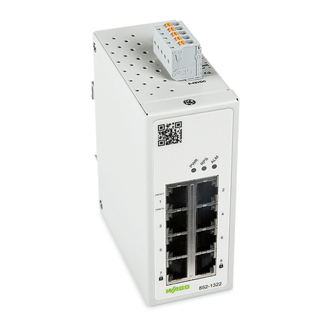
WAGO´s 852-1322 industrial managed switch is a switch with 8 Gigabit-Ports
10/100/1000 BASE-T(X) RJ-45, of which two ports support MAC Security encryption.
This industrial managed switch is easy to configure and install; thus, it can be used in nu-
merous applications including residential applications. It is ideal for plug-and-play local
area network protection with embedded MACsec key agreement that offers security pro-
tection.
MACsec uses GCM-AES to implement point-to-point security for ETHERNET links be-
tween switches. In other words, it can secure a network from a whole host of security
threats, including intrusion, man-in-the-middle, masquerading, passive wiretapping, and
playback attacks. And because MACsec encryption is hardware-based, there is no name-
able added latency.
WAGO’s 852-1322 is ideal for adding an extra layer of security in residential and indus-
trial applications that require compact solutions while delivering high network perfor-
mance up to 97 % of throughput guaranteed with no nameable additional latency.
It also supports a wide operating temperature range of -20 °C to 70 °C and is EN/
IEC(CB)/UL62368-1, and IEC 60068-2-6, IEC 60068-2-27, IEC 60068-2-32. WAGO’s
852-1322 switches is a powerful compact device that can perform under a variety of envi-
ronmental conditions, such as power input voltage, shock, drop and vibration.

852-1322Properties
14 Product manual | Version: 1.2.0
Industrial Managed Switch
4Properties
4.1 Views
4.1.1 Front View
Figure1: Front View of the Industrial Managed Switch

852-1322 Properties
Product manual | Version: 1.2.0 15
Industrial Managed Switch
Table1: Legend for the Figure "Front View of the Industrial Managed Switch"
Pos. Custom Name Explanation
1 PWR Status LED Power input 8Display Elements [}18]
2 RPS Status LED redundant input 8Display Elements [}18]
3 ALM Status LED alarm 8Display Elements [}18]
4 RJ-45 ports (10/100/1000BASE-T(X))
(6)
8Port LEDs [}19]
5 RJ-45 ports (10/100/1000BASE-T(X)
(MACsec) (2)
8Port LEDs [}19]
4.1.2 Top View
Figure2: Top View of the Industrial Managed Switch
Table2: Legend for the Figure “Top View of the Industrial Managed Switch”
Pos. Custom Name Explanation Details
1 - Grounding screw 8Grounding screw [}16]
2 - Connector (male) for power consump-
tion (RPS/PWR/F.G.)
(RPS/PWR/F.G.)
(Item number 2231-105/026-000)
8Power Supply [}16]

852-1322Properties
16 Product manual | Version: 1.2.0
Industrial Managed Switch
4.2 Label
Figure3: Label
Table3: Legend for Figure „Label“
Custom Name Description
Item-No Item number
IN Device input and maximum current and voltage
Ambient Temp Device input and maximum current and voltage
MAC Device MAC information
Default IP Device default IP address
Serial NO Device serial number
Firmware Version (left digit sequence) (02)
Hardware Version (right digit sequence) (02)
QR code Connect to product information by scanning this QR code
4.3 Connectors
4.3.1 Grounding screw
The switch must be grounded. Connect the grounding screw to the ground potential. Do
not operate the switch without an appropriately installed protective earth conductor.
Figure4: Grounding screw
4.3.2 Power Supply
The female connector (Item No. 2231-105/026-000) can easily be connected to the 5-
pole male connector (Item No. 231-435/001-000) located on the top of the switch.
Both PWR and RPS support input voltage between 9 and 48 VDC.
The male connector shows the following pin assignment:

852-1322 Properties
Product manual | Version: 1.2.0 17
Industrial Managed Switch
Figure5: Power Supply Connector
Table4: Legend for Figure “Power Supply"
Connection Custom Name Description
+ RPS Secondary DC input
‑ RPS Secondary DC input
+ PWR Primary DC input
- PWR Primary DC input
F.G. Functional Ground
!
NOTICE
Damage to Property Caused by Electrostatic Discharge (ESD)!
DC Powered Switch: Power is supplied through an external DC power source. Since the
switch does not include a power switch, plugging its power adapter into a power outlet will
immediately power it on.
4.3.3 Network Connections
The industrial managed Switch uses ports with copper connectors and supports ETHER-
NET, Fast ETHERNET and Gigabit ETHERNET
Figure6: Network Connections
Table5: Legend for Figure "Network Connections"
Pos. Description For Details, see Section:
1 6 x RJ-45 connections
(10/100/1000BASE-T(X))
810/100/1000BASE-T(X) ports [}18]

852-1322Properties
18 Product manual | Version: 1.2.0
Industrial Managed Switch
Pos. Description For Details, see Section:
2 2 x SFP connections
(10/100/1000BASE-T(X) (MACsec)
810/100/1000BASE-T(X) (MACsec) ports
[}18]
4.3.3.1 10/100/1000BASE-T(X) ports
10/100/1000BASE-T(X) ports support networks speeds of 10Mbit/s, 100 Mbit/s und 1000
Mbit/s and can be operated in half- and full-duplex transmission modes. These ports also
provide automatic crossover detection (Auto-MDI/MDI-X), with plug-and-play capabilities.
Simply plug the network cables into the ports; they then adapt to the end node devices.
We recommend the following cable for the RJ-45 ports:
• Cat 5e or better with a max. cable length 100 m.
4.3.3.2 10/100/1000BASE-T(X) (MACsec) ports
The 10/100/1000BASE-T(X) (MACsec) connections offer not only the network speeds
of10 Mbit/s,100 Mbit/s and 1000 Mbit/s, but also encrypted data traffic using the
MACSecurity security standard.
4.4 Display Elements
The is equipped with device LEDs and port LEDs. You can see the status quickly with the
device LEDs, while the port LEDs provide information about connection actions.
4.4.1 Unit LEDs
Figure7: Unit LEDs
Table6: Legend for “Unit LEDs” Figure
LED Name Status Description
PWR Primary-Power-LED Green Use the primary power supply.
Off Primary power off or failure.
RPS Redundant-Power-
System-LED
Green Use the redundant power supply.
Off Redundant power off or failure.
ALM Alarm-LED Red No power supply at the primary or secondary (PWR or RPS)
power supply.
Off No alarm reported

852-1322 Properties
Product manual | Version: 1.2.0 19
Industrial Managed Switch
4.4.2 Port LEDs
Figure8: Port LEDs
Table7: Legend for „Port LEDs“ Figure
LED Connection Status Description
LINK/ACT 10/100/1000 BASE T Ports LED
(1 LED for each port)
Green Port in operation
Flashes Data traffic routed via the port
Off No proper link established
100M/1G 10/100/1000 BASE T Ports LED
(1 LED for each port)
Amber Port in operation at 100/1000Mbit/s
Off Port in operation at 10Mbit/s or not
linked
4.5 Technical data
4.5.1 Product
Table8: Technical Data – Device Data
Property Value
Width 45.3 mm
Height 110 mm
Depth 92 mm (from the top edge of the carrier rail)
Weight 441 g
Degree of protection IP30
4.5.2 System Data
Table9: Technical Data – System Data
Property Value
MAC table 16384 entries
Jumbo Frame Size 10kB
Maximum lengths 10/100/1000BASE-T(X): 100m
4.5.3 Power Supply
Table10: Technical Data – Power Supply
Property Value
Supply voltage 9 … 48 VDC
Power consumption, max. 5.8 W
4.5.4 Communication
Table11: Technical Data – Communication
Property Value
Ports (copper, RJ-45) 6x10/100/1000BASE-T(X)
Ports (copper, RJ-45, MAC Security) 2x10/100/1000BASE-T (MAC Security)

852-1322Properties
20 Product manual | Version: 1.2.0
Industrial Managed Switch
Property Value
Standards IEEE 802.3 10BASE-T
IEEE 802.3u 100BASE-TX
IEEE 802.3ab 1000BASE-T
IEEE 802.3x Flow Control, back pressure Flow Control
IEEE 802.1Q for VLAN Tagging (Prioritization of Profinet Packets)
IEEE 802.1p for CoS (Prioritization of Profinet Packets)
IEEE 802.1AE for MAC Security
4.5.5 Environment requirements
Table12: Technical Data ‒ Environmental Conditions
Property Value
Surrounding air temperature, operation -20 … +70 °C
Surrounding air temperature, storage -40 … +85 °C
UL 62368-1 Use Indoor
Pollution degree PD 2
Relative humidity 5 … 95 %, 55 °C
Vibration resistance IEC 60068-2-6
Shock resistance IEC 60068-2-27
EMC immunity to interference EN 55024
EN 61000-6-2
EN 61000-6-1
EMC Emission of interference FCC Part15, SubpartB, ClassA,
ClassB
EN 55032 ClassA and ClassB
EN 61000-6-4
EN 61000-6-3
EN 55011
4.6 Guidelines, approvals and standards
4.6.1 Approvals
The following approvals have been granted for the product:
Conformity Marking
Ordinary Locations UL62368 (E482462)
Note
More information on approvals
You can find detailed information on the approvals online at: üwww.wago.com/<item
number>
4.6.2 Regulations and Standards
Please observe the standards and regulations that are relevant to installation:
Other manuals for 852-1322
1
Table of contents
Other WAGO Switch manuals

WAGO
WAGO 852-1305 User manual

WAGO
WAGO 852-1328 User manual

WAGO
WAGO 852-1322 User manual

WAGO
WAGO 852-101 User manual

WAGO
WAGO 852-1102 User manual

WAGO
WAGO 852-111 User manual

WAGO
WAGO ETHERNET Accessories 852 852-0111 User manual

WAGO
WAGO 852-1111 User manual

WAGO
WAGO 852-112/000-001 User manual

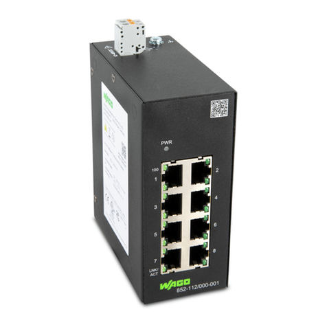
WAGO
WAGO 852-1411/000-001 User manual