6
CLIPPING
Clipping is ideal for removing hair evenly and creating an appearance that may not be
possible with scissors. It is a relatively fast and effective way to obtain a manageable length
for the coat, although it may be necessary to provide regular breaks for you and the dog.
Toachievethebestresults,followtheadvicebelowanddonotexpecttogetitrightrsttime.
Clippingcantakeagreatdealofpracticetoachieveasmooth,evennish.Ifyourequire
informationspecictoyourdog,werecommendyouconsultaprofessionalgroomerorvet
for further advice.
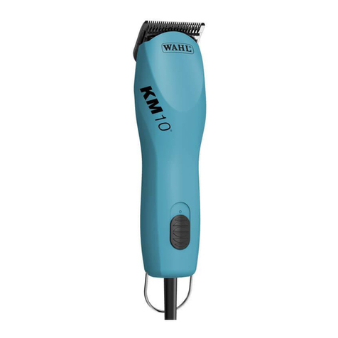
Choosing the Right Clipper
When you have decided that you want to clip your dog at home, it is essential that you select
thecorrectclipperforyourpet’scoat.Considerthetypeofhair,isitthick,courseorne?
Thenconsiderhowthickthecoatis,istheremorethanonehairtype?Ingeneral,thethicker,
denserandcurlierthecoat,themorepowerwillberequiredtocutthroughitefciently.
For further information on coat types see page 30-31.
Before you Start:
• Wash and dry the dog to ensure any dirt or debris is removed from the coat. Grit and coat
grease will blunt clipper blades prematurely.
• Ensure the hair is dry and well combed through, free from any knots or tangles.
• Ensureyouhavetherightclippersforthejob.
• Oil the blades and check the equipment is in good working order before you start.
• Ifyouareusingarechargeablemachineensurethereissufcientbatterychargeotherwise
the blades may pull at the hair instead of cutting it.
• Allow the dog time to get accustomed to the noise and vibration of the clippers.
• Intheearlystagesitmaybebenecialtoasksomeonetoholdyourdogforyou.
• Keeptheclipperbladeswelloiledandclearofcuthair.Hotbladescanindicateinsufcient
oil, or the blades may be blunt and require sharpening or replacing.
Tips on Clipping:
• Thersttimeyoucutyourpet’shair,onlycutasmallamountuntilyouareaccustomed
to how long each guide comb leaves the hair. Start with the largest comb and then use
shorter combs until the desired result is achieved.
• Use the attachment combs to increase the clipping length. The combs included with the kit
allow various cutting lengths.
• For a uniform result allow the clipper to pass its way through the hair – do not try to force it
through at a faster rate.
• Some breeds need to be clipped more frequently than others.
• Whenclippingforthersttime,theclippingprocesswillbeslow.Trytomovewithyour
dog when clipping. After a few sessions, you will develop your own comfortable style and
grooming will take less time.
• Always clip with the natural fall of the hair on the body and legs. Working against this
natural fall will cut the coat approximately 50% closer. This technique may be used when
clipping the face, throat, feet and tail.
