Walinga AL 1314 User manual

OPERATOR’S MANUAL
FOR
DROP-THROUGH
ROTARY AIRLOCKS
MODELS: AL 1314 , AL 1618 , AL 2224

2

PCS Contact Info March 11,2020
Dear Customer,
Thank you for choosing WALINGA PNEUMATIC CONVEYING SYSTEMS. For your convenience, should you require
any information related to Parts, Service or Technical Engineering, please contact one of the following Walinga
Personnel in Guelph at 1-888 925-4642 unless noted*
TECHNICAL - ENGINEERING:
Duane Swaving *226-979-8227 pcs.techsupport@walinga.com
Ken Swaving *519 787-8227 (ext:100) k[email protected]
To speak with a Walinga Warranty Coordinator, contact:
Canada 1-888-WALINGA (ext 258)
Australia 07-4634-7344 Email – [email protected]
GUELPH SERVICE:
Kevin VanderZwaag *(519) 763-7000 (ext:273) [email protected]
ORIGINAL PARTS SALES:
Ontario and Eastern Canada:
(ext: 224) [email protected]
Parts Department Fax: (519) 824-0367
Manitoba and Western Canada:
Chad Yeo * 204-745-2951 (ext: 424) chad.[email protected]
USA:
John VanMiddlekoop * (800) 466-1197 (ext 3) [email protected]
SALES MANAGER:
Tom Linde *519-787-8227 (ext 5) [email protected]
Peter Kingma (800) 466-1197 jpk@walinga.com
CORPORATE HEAD OFFICE:
5656 Highway 6N
RR#5, Guelph, Ontario, N1H 6J2
PHONE: (888) 925-4642 FAX: (519) 824-5651
www.walinga.com
FACTORY DISTRIBUTION AND SERVICE CENTRES:
938 Glengarry Cres. Fergus, Ontario Canada N1M 2W7
Tel: (519) 787-8227 Fax: (519) 787-8210
1190 Electric Ave. Wayland , MI.USA 49348
Tel: (800) 466-1197 Fax: (616) 877-3474
70 3rd Ave. N.E. Box 1790 Carman, Manitoba Canada R0G 0J0
Tel: (204) 745-2951 Fax: (204) 745-6309
24 Molloy St, Toowoomba, Queensland Australia 4350
Tel: 07-4634-7344 Email: m[email protected]

4
Walinga
Rotary Airlock
Operator's Manual
Model AL 1314 , AL 1618 , AL 2224
-TABLE OF CONTENTS –
SECTION DESCRIPTION PAGE
Technical Support…………………………… 3
1 INTRODUCTION………………………………… 5
1.1 Principle of Operation …………………………… 5
1.2 Airlocks & Rotary Seals ………………………… 5
2 KEY OPERATING GUIDELINES………………. 5
2.1 Direction of Rotation……………………………… 5
2.2 Tip Clearances……………………………………. 5
2.3 Rotor Clearances ………………………………… 5
2.4 Flexible Tip Wiper………………………………… 6
2.5 Rotor bearings……………………………………. 6
3 SCHEDULED MAINTENANCE ………………... 6
3.1 Commissioning Period…………………………… 6
3.2 Maintenance Recommendations……………….. 6
4 TROUBLESHOOTING………………………….. 8
4.1 Rotor Grinds during Operation…………………. 7
4.2 Airlock Stalls or Motor Overloads……………… 7
4.3 Air Blow-Back Restricts Feed Inlet……………. 8
4.4 Airlock Tip/Flexible Tip Wiper Breaks………… 8
5 AIRLOCK MAINTENANCE …………………… 9
5.1 Tools Needed for Servicing Blade Tips………… 9
5.2 Replacing Damaged Blade Tips………………… 9
5.3 Adjusting Tip Clearances………………………... 10
5.4 Re-machining Casing …………………………… 10
6
6.1
6.2
6.3
ROTARY AIRLOCK COMPONENTS
A/L 1314 …………………………………………..
A/L 1618 ………………………………………….
A/L 2224 …………………………………………..
12
12
14
16

5
1 INTRODUCTION
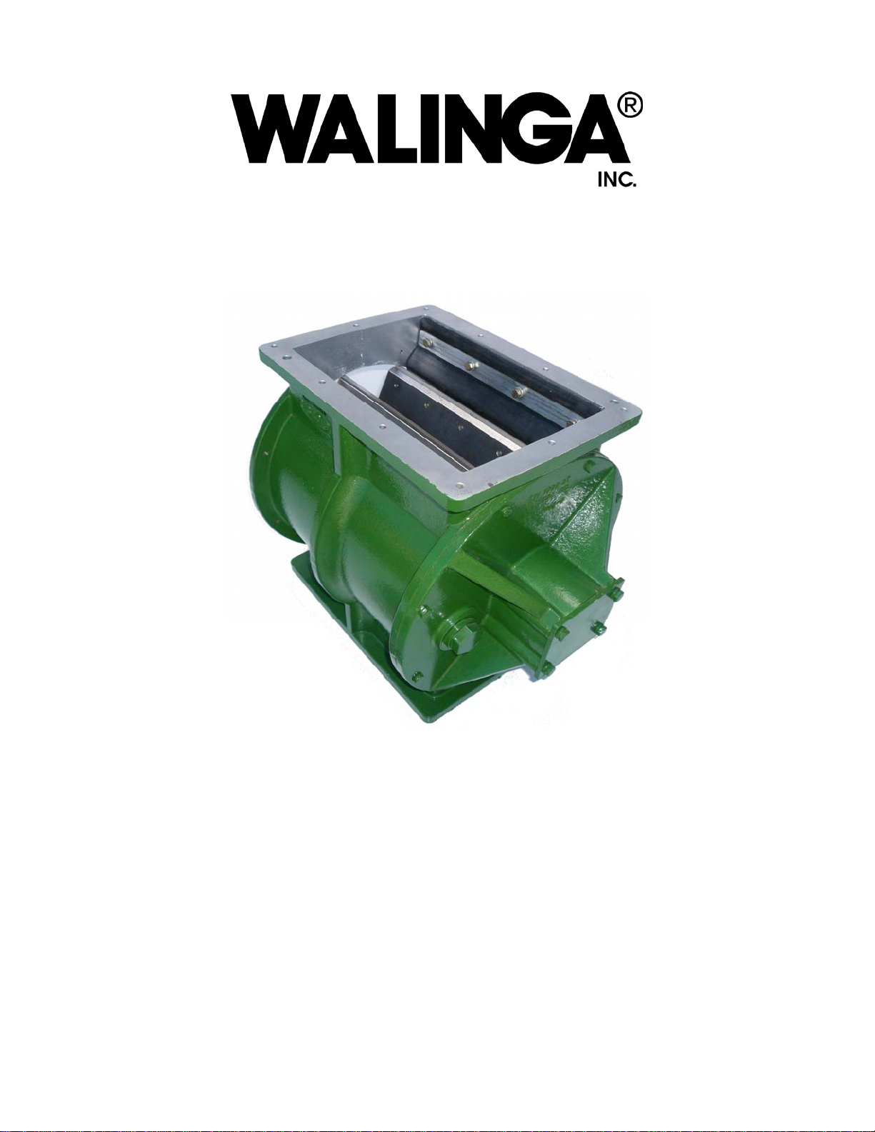
1.1 Operating Principles
Walinga Rotary Airlocks use a multi-bladed
rotor to move material. The rotor picks up
material in the pocket between each 2 blades
as it rotates past the top feed inlet area. It
then transfers the feed through the airlock
casing to either a ‘blow-through’ or ‘drop-
through’ chamber at the bottom.The airlock
often features low clearance wear tips on
each rotor. These are both adjustable &
replaceable and usually made of high-wear
material. Other tip materials and designs may
be used for specialized applications. The tips
deliver a high degree of sealing between the
material supply chamber and the outlet
area.During operation the multi-bladed rotor
fills with material at the inlet (top) side of the
unit. This material moves with the rotating
blades and drops through to either the' blow-
through' or 'drop-through' chamber below.
‘Blow- Through’ designs use a pressurized
air-stream entering the inlet port to move
material through the chamber to a pneumatic
transfer line connected to the outlet port.
‘Drop- Through’ designs drop the product out
of the airlock under gravity through a large
rectangular discharge port under the unit.
1.2 Airlocks & Rotary Seals
The terms ‘airlock’ / ‘rotary valve’ and 'rotary
seal' are sometimes used to describe the
same item of equipment. In general an
‘airlock' provides a higher level of sealing and
is more easily adjusted than a 'rotary seal'.
Their heavy duty cast construction and high
level of sealing suit them well to commercial
applications - especially when using
pressurized delivery line.
2 KEY OPERATING GUIDELINES
2.1 Direction of Rotation
The airlock rotor MUST MOVE COUNTER -
CLOCKWISE WHEN VIEWED FROM THE
DRIVEN END.
Do not operate for extended periods in reverse
direction.
PROLONGED OPERATION IN REVERSE
DIRECTION OF ROTATION RESULTS IN HIGH
WEAR RATES IN THE CASING AND LOSS OF
PERFORMANCE.
Operating for short periods in reverse direction is
acceptable but only to assist in clearing objects
jammed between the blades and casing. Reverse
operation also increases product damage because
the flexible tip wiper is not effective when the rotor
moves in a clock-wise direction (viewed from the
driven end).
2.2 Tip Clearances
MODEL 1314 1618 2224
Maximum 0.014 0.016 .020
Minimum 0.005 0.006 .008
Preferred 0.006 0.007 .009
Max. Reset 0.009 0.010 .010
An adjustable tip fits at the outer edge of each rotor
blade. These tips provide a seal as the rotor
transfers material from the intake to the outlet area.
Efficient operation requires a close fit between the
top of each blade tip and the airlock casing.
Excessive clearance allows ‘blow-back' of air
through the airlock causing uneven flow and
reduced performance. Check and adjust airlock
blade tip clearances regularly as part of a scheduled
maintenance program. Routine maintenance of tip
clearances is especially important in materials with
high abrasion characteristics.
2.3 Rotor Clearances
Airlock rotors are not adjustable, so clearances can
not be changed. If the clearance between the rotor
and the endplate is too high, no amount of tip
adjustment will improve performance. If the
rotor/endplate clearance total is at or greater than
the total clearance in the chart below, the airlock
should be replaced.
Model 1314 1618 2224
Clearance/side 0.010 0.012 0.015
Total
Clearance 0.020 0.024 0.030

6
2.4 Flexible Tip Wiper (If applicable)
The intake chamber has a flexible tip wiper
bolted to the left hand side (viewed from the
driven end). The tip wiper levels material as it
moves out of the intake area into the casing.
This leveling action ensures even flow,
reduces wear rates and avoids' out-of-round'
wear within the casing.
- Check the flexible tip wiper during every
scheduled tip servicing –
2.5 Rotor Bearings (ball bearing or
tapered bearing type)
Ball bearing type: Each rotor shaft bearing is
housed in a sealed housing. The housing must
remain sealed and slightly lubricated to prevent
corrosion that will prevent these bearings from
floating. Remove the cover plate only if
operational problems are suspected.
Ensure that the housing is slightly lubricated before
replacing the cover.
Tapered bearing type: Each rotor shaft bearing is
housed in a sealed grease box and does not require
routine lubrication. Remove the cover plate only if
operational problems are suspected. Ensure that
the grease box is fully packed with grease before
replacing the cover.
3 SCHEDULED MAINTENANCE
The intervals suggested on the schedule below are typical only. Adapt it to suit the existing
scheduled maintenance program.
3.1 Commissioning Period
Perform commissioning checks within the first 2 hours of operation and again within 10 hours. Step
through the' 500-hour' maintenance items at both the 2 hour and 10 hour commissioning checks.
3.2 Maintenance Recommendation
Typical Interval
Maintenance Items
Every:
500 hours total operation or
500 tonne wheat equivalent or
3 months intermittent operation
which-ever occurs first.
Every:
2000 hours total operation or
2000 tonne wheat equivalent or
12 months intermittent operation
which-ever occurs first
(1) Tighten Bolts/fasteners.
(2) Adjust drive tension/alignment & lubricate if
necessary.
(3) Listen for excessive noise from bearings
and rotor.
(4) Check temperature levels around
bearings/drive motor/rotor casing.
(5) Inspect for air leaks at all inlet and outlet
flanges.
(1) Inspect wear tips on blades and replace if
damaged.
(2) Inspect flexible tip wiper and replace if
damaged .
(2) Adjust clearances on all blade tips.

7
4 TROUBLESHOOTING
The Walinga airlock delivers long periods of trouble-free operation when operated and serviced
correctly. This trouble-shooting guide will help identify and solve operating problems if they occur.
WARNING -
ISOLATE THE AIRLOCK FROM YOUR POWER SUPPLY
BEFORE CLEARING OR ADJUSTING
Operating Problem Possible Cause & Recommended Action
4.1 Rotor Grinds During
Operation
4.1.1) Rotor Blade Tips not fully
seated after adjustment
4.1.2 Incorrect Direction of
Rotation
4.1.3 Bearing Failure
It is normal to hear a light grinding noise for several hours after
adjustment of the airlock tip clearances. This noise will
disappear after the tips seat fully on the casing.
If the noise is excessive the tips may be adjusted too tight
against the casing. Re-adjust tip clearances as described in
the Maintenance section.
The airlock is designed to operate continuously in one direction
only. Check that the shaft rotates in an counter clockwise
direction when viewed from the driven end of the unit.
Continuous operation in reverse will cause excessive wear and
may damage the rotor tips, tip wiper, casing and bearings.
Remove bearing cover plates at each end of the airlock .Follow
normal ball bearing replacement practices.
If equipped with tapered bearings, ensure that the bearings
and housings are fully packed with grease before replacing
covers.
Always re-check clearances between end of rotor blades
and end plates after replacing bearings. See maintenance
section for guidance.
4.2 Airlock Stalls Or Motor
Overloads
4.2.1 Obstruction in Airlock
Prevents Blade Rotation
(a) For units with Reversible Speed Controller: Change the
rotational direction of the airlock briefly then return to correct
direction. Repeat this several times until the object (for
example, bolts or metal) falls sideways into the blade area and
clears. If this fails, move to (b) ...
Caution: Changing the direction of rotation by reversing the
wiring on 3-phase electric motors is not recommended.
Impact damage may result.
(b) For units without Reversible Speed Controller: Isolate the
power supply to the unit - Essential! Remove obstruction
manually. Access obstruction through an inlet or discharge
opening (after removing piping or ducting) or via an inspection
hatch if provided. If still unable to clear the obstruction, remove
the complete airlock unit for attention.

8
Operating Problem Possible Cause & Recommended Action
4.2.2 Prolonged Operation in
Reverse Direction
4.2.3 Tip/Casing Clearances too
Tight
4.2.4 Drive-line adjusted
Incorrectly
4.2.5 Faulty Drive Motor
The Walinga airlock operates in an counter-clockwise direction
when viewed from driven end. Damage to rotor blades and tips
due to prolonged operation in the opposite direction may cause
jamming. The unit may need to be removed to assess rotor and
casing damage - repair or replace.
Re-set clearances between blade tips and casing as
described in maintenance section.
If fitted with chain/sprocket drive check tension,
alignment and flexibility of links.
Service drive motor.
4.3 Air Blow-Back
Restricts Feed Inlet
4.3.1 Blade Tips and Casing
4.3.2 Airlock Casing not
Pressure-vented
Note: Venting is not usually
needed in free-flowing materials
with high bulk densities eg cereal
grain.
Remove airlock and adjust tips to correct clearance as
described in maintenance section.
Excessive clearance causes operating problems including
bridging and erratic flow. Prolonged operation with high
clearances wears the casing unevenly - this will result in lower
performance even after adjustment of tips.
Quick test while operating
a) Loosen vent plug in end plate - item on diagram.
(b) Operate airlock to transfer feed -first with plug in end plate
and then removed.
(c) Check whether flow improves with plug removed. If flow
improves fit a pressure-vent kit.
Custom-designed vented hoppers may be used for fine
materials like milled meals.
CAUTION; Both air AND excess feed may blowout of vent
hole during test. KEEP YOUR FACE WELL CLEAR OF
VENT HOLE.
4.4 Airlock Tip Or Flexible
Tip Wiper Breaks (if
applicable)
4.4.1 Prolonged Operation in
Reverse Direction of Rotation
4.4.2 Tip Wiper Fouling on
Blade Tips
Airlock must operate in counter-clockwise direction when
viewed from driven end. Change direction and service tips or
flexible tip wiper if necessary.(only applicable if tip wiper is
used)
Re-adjust clearance of flexible tip wiper - see Maintenance
Section 5

9
5. AIRLOCK MAINTENANCE
Wear tip and wiper blade adjustment are on-going maintenance items. They must be scheduled for
attention at regular intervals. Correct adjustment of tip and wiper blade clearances is essential to
ensure efficient operation. Excessive clearances between rotor tips and airlock casing wilt reduce
performance and increase both the rate and non-uniformity of wear. By following the procedure below
you will achieve a consistent result each time the airlock is adjusted. Don't be tempted to take short cuts
- performance will suffer.
- WARNING-
ISOLATE THE AIRLOCK FROM POWER SUPPLY
BEFORE CLEARING or ADJUSTING
Ensure that you have clear access into the top inlet of the airlock unit before attempting to adjust wear
tips. Remove the unit from its mounting point if necessary. Note that two (2) sets of feeler gauges will
make airlock tip adjustment easier, faster and more accurate. You can also use shim metal of the
specified thickness as an alternative to feeler gauges.
5.1 Tools Needed For Servicing Blade Tips
• 3/8" Socket Ratchet Arm
• 3/8" Socket Extension (30cm)
• ¼ inch allen key to suit Tip Retaining Screws
• Wear Tip Retaining Screws (phillips head) &
Washers if existing screws are damaged.
• 3/8" socket driver to suit ¼ inch allen key
• Feeler Gauges (2 sets) or Shim Metal Sheet of
specified thicknesses.
• Permanent Marker Pen
• Small Pry Bar 20 in (50 cm) long
• 2 x 1/2" (50mm x 13mm) ring/open end
spanner
• Scraper (to remove flange sealant)
• Flange Sealant (eg silicone-based) or
Gaskets. Ensure that silicone-based sealants
are accepted for use in your industry.
Note:Tip Retaining Screws, Shim Metal & Spring
Washers are available from Walinga Inc.
5.2 Replacing Damaged Blade Tips
If one edge of an airlock blade tip is damaged it
may be possible to reverse it and use the other
edge. Stainless steel tips may be re-ground to a
'true' edge - this may be repeated until no
adjustment is left in the screw slots.
If tips are badly damaged - replace them. Always
check the condition of replacement tips before
installing. They must not be bent and all four edges
must be true and undamaged.
(a) Loosen and remove tip retaining screws using
the ¼” allen key then remove tip from
casing – bottom ports on Blow-
Thru units are a convenient removal
point.
(b) Insert new or reversed tip and
measure clearances between tip
ends and end plates.
File or grind the ends of new tips if
necessary to ensure that the tips are
not longer than the rotor blades.
(c) Fix tips loosely to rotor blade with tip
retaining screws. Follow the
adjustment method in following
section to set correct clearances
between tip edge and casing.

10
5.3 Adjusting Tip Clearances
1. Place an identifying number on the leading
side of the first blade e.g .. #1'. This is
important - it is easy to miss a tip unless
every blade is marked as it is adjusted.
2. Loosen the retaining screws holding the
wear tip on blade #1. You wilt need a ¼”
allen key.
3. Rotate the blade until it is about 1” (25mm)
inside the airlock casing opposite the
flexible tip wiper. Note: Blades are angled
slightly on the shaft so one end will be
further inside the casing than the other.
4. Place a feeler gauge (or shim) between the
tip and casing 4” (10 cm) from each end of
the blade tip (2 feelers or shims needed) -
use 0.008" (8 thousandths of an inch)
5. Gently lever the blade upwards until it
contacts the feeler gauges or shims.
6. Tighten tip screws ... CENTRE SCREW
FIRST!
7. Rotate the airlock counter-clockwise for a
full revolution (viewed from driven end) and
listen for binding noise between the tip and
the casing. A light grinding noise is normal
and will disappear as tips seat fully during
first few hours of operation.
8. Repeat the Tip Adjustment Steps for
Each Blade. Mark each blade with its
number (i.e. #2, #3 etc) as you work on it to
ensure that none are missed.
9. Adjust the Flexible Tip Wiper. Each tip
should contact the flexible tip wiper lightly
as the rotor turns. Replace if Wiper is worn
excessively or damaged .
• Check that Rotor turns
COUNTER-CLOCKWISE
after Connecting Power·
(viewed from driven end)
5.4 Out-Of-Round Casing Wear
An airlock that has excessive out-of-round
wear in casing will operate poorly. Airlocks
wear rate and out-of-round wear increase
greatly if the rotor is operated in the
incorrect direction. It MUST rotate counter-
clockwise when viewed from the shaft
(driven) end.
To check for excessive out-of-round wear in
the casing:
1. Adjust airlock tip clearances as per 5.3
2. Any clearances above .020” will reduce
performance.
3. If tips need setting at higher than .11”
performance may be unacceptable
especially in light feeds. The out-of
round casing will need machining.
Airlocks must be re-machined by tool
shops with experience in this type of work.
Inaccurate alignment of end-plates and
casing is the most common error in a re-
machining job. They MUST align on the
same shaft centre-line. End-plates would
normally be dowelled to the casing after
machining to ensure correct alignment.

11

12
6.1 ROTARY AIRLOCK MODEL AL 1314 COMPONENTS

13
6.1 ROTARY AIRLOCK MODEL AL 1314 COMPONENTS CONT’D

14
6.2 ROTARY AIRLOCK MODEL AL 1618 COMPONENTS

15
6.2 ROTARY AIRLOCK MODEL AL 1618 COMPONENTS CONT’D

16
6.3 ROTARY AIRLOCK MODEL AL 2224 COMPONENTS

17
6.3 ROTARY AIRLOCK MODEL AL 2224 COMPONENTS CONT’D

18
CORPORATE HEAD OFFICE:
RR#5 Guelph, Ontario, N1H 6J2
PHONE (888) 925-4642 FAX (519) 824-5651 www.walinga.com
FACTORY DISTRIBUTION AND SERVICE CENTRES:
1190 Electric Ave. Wayland, MI.USA 49348
Tel (800) 466-1197 Fax (616) 877-3474
938 Glengarry Cres. Fergus, Ontario Canada N1M 2W7
Tel: (519) 787-8227 Fax: (519) 787-8210
70 3rd Ave. N.E. Box 1790 Carman, Manitoba Canada R0G 0J0
Tel (204) 745-2951 Fax (204) 745-6309
220 Frontage Rd. Davidson, Saskatchewan Canada S0G 1A0
Tel: (306) 567-3031 Fax: (306) 567-3039
PRINTED IN CANADA
This manual suits for next models
2
Table of contents
Other Walinga Industrial Equipment manuals
Popular Industrial Equipment manuals by other brands

Terex
Terex Genie Genie Lift Operator's manual

erowa
erowa MTS-BasePlate 200x410/250 P manual

JUKI
JUKI AF05 instruction manual

PCB Piezotronics
PCB Piezotronics J352C04 Installation and operating manual

Sima
Sima POLINI KIDS FUN 890 Masha and the Bear quick start guide

SKF
SKF TMMA 100H/SET Instructions for use

Paradyne
Paradyne Hotwire 8775 installation instructions

irritec
irritec Rotodisk IU4304 Operating and maintenance instructions

TSI Instruments
TSI Instruments CH-60 manual

Arbpro
Arbpro LD1 instruction manual

GSi
GSi VersaLoop 8 owner's manual

Carlisle Fluid Technologies
Carlisle Fluid Technologies Ransburg AER4006-01 Service manual