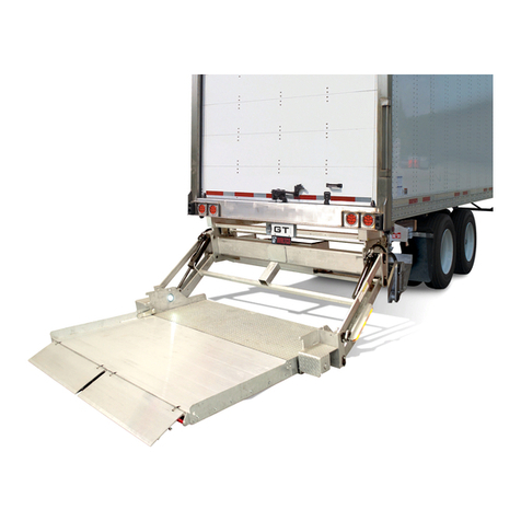
Waltco Lift BZ-33 User manual

EO:10338 Rev 02
10-2017 80117221
Installation Manual
BZ-33, BZ-44 Gen 7
3300 lb. & 4400 lb. Capacity Cantilever Liftgates
GR02912
Last Change
Date Pages Description
03/2018 17-23 REVISED SCHEMATICS
Waltco Lift Corp. Waltco Lift Corp. Waltco Lift Inc.
Corporate Office United State United States Canada
285 Northeast Ave. 620 S Hambledon Ave. 90 North Queen St.
Tallmadge, OH 44278 City of Industry, CA 91744 Etobicoke, ON M8Z 2C5
P: 330.633.9191 P: 626.964.0990 P: 888-343.4550
F: 330.633.1418 F: 626.964.0149
www.waltco.com Phone: 800.411.5685

Table of Contents
Introduction........................................................................................................................3
Safety Information..............................................................................................................4
Liftgate Terminology ..........................................................................................................6
Basic Mounting Requirements...........................................................................................8
Liftgate Installation...........................................................................................................10
Electrical Installation........................................................................................................16
Electrical Schematics....................................................................................................... 17
Electrical Trouble Shooting..............................................................................................27
Battery Connection……………………………………………………………………………… 32
Fill Reservoir.................................................................................................................... 34
Platform Install.................................................................................................................35
Up-Stop............................................................................................................................36
Platform Tilt/Cylinder Adjustment.....................................................................................39
Bumper............................................................................................................................43
Swing Door Applications..................................................................................................43
Check Operation..............................................................................................................45
Placement of Decals........................................................................................................47
Lubrication Instructions.................................................................................................... 50
Final Inspection................................................................................................................51
Optional Kit Instructions:
Aux Battery Kit (Truck)..................................................................................................... 52
Kit #80001066
Aux Battery Kit (Trailer)
Kit #80001069
Full Door Seal Kit.............................................................................................................57
Kit #80000573
Cycle Counter Kit.............................................................................................................62
How to Order Parts.......................................................................................................... 63
Improper installation of this liftgate could result in severe personal injury or
death.
Read and understand the contents of these instructions before proceeding.
When installed, this liftgate must not alter or prevent vehicle compliance to any
existing state or federal standards.
Each chassis manufacturer’s recommendations should be consulted for
compliance.
page 2

INTRODUCTION
If anyone observes improper installation, improper operation, or damage, they should immediately
contact a qualified person for assistance and correction. We strongly urge anyone that has any
questions or doubts as to the installation, condition, use, operation, maintenance or repair of the liftgate
to contact us at Waltco where we have qualified personnel that will be happy to assist you. Telephone
numbers and addresses of these locations are listed in the Owner’s Manual and Installation
Instructions.
INSTALLATION
Waltco liftgates should only be installed by those with sufficient basic skills to understand the
installation and operation of the liftgate, along with the equipment on which the liftgate is being
installed. Waltco’s installation instructions are not intended to give rationale for all the instructions that
are given; however, it is the intent of these instructions to give the installer both the operations and
what we believe to be the most desirable sequence of implementing these operations. These
instructions can in no way expand into an area where they will replace a qualified person, or clear
thinking and a basic knowledge that must be possessed by the installer.
It has been our experience that a knowledgeable journeyman following these instructions and
observing the operation of the liftgate will have a sufficient comprehension of the liftgate to enable this
person to troubleshoot and correct all normal problems that may be encountered.
Failure to follow the installation instructions, adjustments and mounting dimensions may result in
improper and unsafe operation of the liftgate. Unauthorized alterations of the liftgate can cause an
undesirable and dangerous condition.
OWNER’S MANUAL
The Waltco Owner’s Manual is intended to act as a guide for operation and routine maintenance but
is no way intended to encourage usage or repair of the liftgate by those who are not qualified to do so.
The contents of the owner’s manual include, but are not limited to general operation instructions,
routine lubrication, parts lists, and an outline of things that should be checked but may not be obvious
to those not technically qualified. This manual assumes the liftgate is properly installed, undamaged
and operates correctly. Improper installation, improper operation, or damage should be immediately
corrected by a qualified person.
INSPECTION
As part of the regular inspection of a liftgate and after damage or suspicion of an overload, inspect
for wear or structural damage and make necessary repairs or replacements. Check all structural
components and their attachment to the liftgate for cracked welds, loose fasteners, wear and part
deformation. Check cylinder and hose for leaks. Inspections and repairs should be made by a qualified
mechanic.
REPLACEMENT PARTS
Use only Waltco original equipment replacement parts. Components of other liftgate manufacturers
may outwardly appear to be the same but are not interchangeable with Waltco products. Waltco
components are specifically designed for safety requirements, reliability and compatibility with our
products. Refer to your Waltco parts manual when ordering parts. NOTE: When ordering, give model
and serial number of liftgate.
DECALS
It is important that every vehicle that has a WALTCO Liftgate have legible DECALS clearly posted on
the vehicle and an OWNER’S MANUAL in the vehicle at all times as a guide for proper operation and
maintenance.
Additional DECALS and OWNER’S MANUALS can be obtained from WALTCO LIFT CORP.
80101388 Rev 03 EO 7820
page 3

Chapter 1 Safety Information
80101253 Rev 04 EO 6309JJ
WARNING
Read, understand, and follow all of the warning listed below.
Failure to follow these warning could result in severe personal injury or death.
• Read and understand the Owner’s Manual, all decals and warning on liftgate before operating liftgate.
• Do not operate liftgate without a thorough knowledge and understanding of the operation of the liftgate.
•Liftgate hazards can result in crushing or falling.
•This liftgate is designed for loading and unloading of cargo. If personnel are required to ride liftgate, observe
and familiarize yourself with the liftgate operation, decals and manuals. Ensure stable footing at all times.
•Do not ride liftgate with unstable loads.
•Wheeled loads must be properly retained from rolling.
•Tall, high center of gravity loads must be retained from falling over.
•Never overload liftgate:
Load platform as close to the vehicle, and towards the middle of the platform as possible. Refer to owner’s
manual and capacity decal of liftgate for maximum load and load placement.
•Keep hands and feet clear of all potential pinch points.
•Never use liftgate if it makes any unusual noise, has unusual vibration, raises or lowers unevenly, or fails to
operate smoothly.
•Never use liftgate if it shows any signs of structural damage such as cracked welds, bent or distorted
members.
•Do not attempt any repairs unless you are qualified to do so. Care should be taken when work is performed
on a disabled liftgate located near moving traffic. When possible the vehicle should be moved away from
traffic areas for repair. Precautionary measures should be taken to ensure personal safety including those
recommended in Federal Motor Vehicle Safety Standards 571.125.
•When welding to liftgate, or liftgate components, take all necessary safety precautions, including using
respiratory protection and other pertinent personal protective gear when welding harmful materials.
• All protective covers, guards, and safety devices must be in place and access doors closed before operating
liftgate.
•Do not allow anyone to stand in, or near area, in which Platform will open and close before opening or closing
Platform.
•Do not allow anyone to stand near the Platform where a falling load could land on them.
•Platform is always to be properly stored and secured for transit. See the Owner’s Manual for details.
•Take care to retain cargo during transit for liftgate Platforms which function as the tailgate or door of the cargo
area. Small objects can fall through the space between the vehicle and the folded Platform.
•A Lock-Out device or Shut-Off Switch should always be used to prevent unauthorized use of liftgate.
•For liftgates with Runners, never use liftgate if Runners do not travel freely and smoothly.
•For liftgates with Roller Lifting Chain, the Chain should be replaced every (5) five years or 15,000 cycles,
whichever comes first. Replace only with Waltco approved Roller Chain.
•Never transfer loads which exceed lifting capacity on or over any part of the Platform unless the liftgate is
equipped with a special reinforced Platform and Platform Support Bars for use when the Platform is used as
loading ramp (dock board). Refer to the “Using Platform as a loading ramp” Chapter in the Operation
Instructions of the BZ/RZ series Owner’s Manual.
•For liftgates equipped with Trailer Hitches, never exceed the rated capacity of the hitch. Do not exceed the
vehicle’s weight rating. Refer to the vehicle’s Owner’s Manual.
•Vehicle must comply with all state and federal standards.
•Follow the “Maintenance Guide” chapter in the Owner’s Manual.
page 4

Chapter 1 Safety Information
80101253 Rev 04 EO 6309JJ
Liftgates with Tilt Function
•Proper use of the Control Switches is of extreme importance.
•Improper use of Tilt Switch could cause load to fall from the Platform or damage the liftgate.
•Platform should be in a generally horizontal position when raising or lowering with a load.
•In any tilt position, the Platform may vary from level while raising or lowering the Platform.
Liftgates equipped with spring operated Cam Closer
•Replace Cam Release Spring every five (5) years or 15,000 cycles, whichever comes first.
RGL-Series Liftgates
•Make certain Platform Brake mechanisms are operating properly.
•The Runners are always to remain powered up against the Upstops Pins when in transit.
•Inspect Cables every three (3) months or 750 cycles, whichever comes first. Cables must be replaced if they
show signs of wear, distortion, kinking or if any broken wires are visible
•Replace cables every five (5) years or 10,000 cycles, whichever comes first.
This is the safety alert symbol. This manual uses this symbol to alert you to potential personal injury
hazards.
Obey all safety messages that follow this symbol to avoid personal injury or death.
SIGNAL WORDS
WARNING
Indicates a potentially hazardous situation, which if not
avoided, could result in death or serious injury.
Black letters on an orange background
CAUTION
Indicates a potentially hazardous situation, which if not
avoided, may result in minor or moderate injury. May
also be used to alert against unsafe practices.
Black letters on a yellow background.
NOTICE
Indicates a potentially hazardous situation, which if not
avoided, may result in property damage.
NOTICE
WARNING
CAUTION
page 5

Chapter 2 Liftgate Terminology
1. Platform
2. Mount Tube
3. Pump and Motor Tray
4. Lift Arm
5. Bumper
6. Lift Cylinder
7. Tilt Cylinder
8. Upper Lift Arm Pin
9. Lower Lift Arm Pin
10. Upper Lift Cylinder Pin
11. Lower Lift Cylinder Pin
12. Upper Tilt Cylinder Pin
13. Lower Tilt Cylinder Pin
14. Marker Lights
15. Sill Extension
16. Mount Plates
17. Cart stop (optional)
14
14
17
17
15
16
1
GR00828
12
75
3
13
11
6
2
9
6
5
5
7
8
4
10
14
14
GR00829
page 6

Chapter 2 Liftgate Terminology
Explanation of Specification Tag
BZ33 G7 Level Lift 3300 lbs.
BZ44 G7 Level Lift 4400 lbs.
GR00241
LOCATION OF
SPECIFICATION TAG
Can be found on driver’s side, end of mount tube.
GR02226
Usually found
on this end
On some older liftgates
may be located here
Mount Tube
MODEL NUMBER
RATED
CAPACITY
Based on an evenly
distributed load on the
platform flat surface.
SERIAL NUMBER
of liftgate. To be used
when ordering parts or
when contacting Waltco
for service or warranty
questions
DATE OF
MANUFACTURE
Month / Year
page 7

Chapter 3 Basic Mounting Requirements
DETERMINE MOUNTING D
IMENSIONS
Determine bed height. Measure from top of vehicle floor
down to ground.
Verify which length arms liftgate has.
NOTE: All dimensions when vehicle unloaded on
horizontal surface.
IMPORTANT! Do not exceed given A- dimension or
max bed height. This can cause damage to liftgate and
improper operation of liftgate.
Additional mounting configurations and dimensions may
be available by contacting the Waltco Engineering
Department.
GR00494
FRAME WIDTH
Liftgates can be mounted to trucks and trailers with max
frame width 45- 1/2”.
Additional mounting configurations and dimensions may
be available by contacting the Waltco Engineering
Department.
GR00655
MOUNTING BRACKETS
Mounting brackets height may need to be trimmed in
order to achieve desired A- dimension. After
modification a minimum of 6 of the outer holes must
remain available for use.
IMPORTANT! Do not modify mounting bracket bolts,
nuts or mounting surfaces that are in contact with mount
tube.
GR02987
1-1/8
13-1/4
8-1/4
3-1/4
12
45-1/2” MAX
77- 3/4”
MOUNT TUBE
CLEARANCE
SILL DEPTH
“A”- DIMENSION
GROUND
CLEARANCE
GROUND
FLOOR LEVEL
BED
HEIGHT
1-3/4”
Note!
Always use the smallest A-
dimension possible.
page 8

Chapter 3 Basic Mounting Requirements
NOTE:
Mount tube must be installed at least 1-5/8” below
vehicle chassis to allow room for mounting brackets.
GR00496
INSTALLATION DIMENSIONS
NOTE:
B height dimensions are the maximums for the unloaded vehicle.
BZ-33/44 Short arm, 29-1/2" Optional
A-Dimension
Bed Height
Maximum sill depth
Mount tube clearance
15.5
43
4
33.00
18
45
5
31.5
20
47
5.5
30
21.75
49
6.5
28.5
23.75
51
7
26.25
25.5
52.5
7.75
24.5
BZ-33/44 Long arm, 34-1/4" Standard
A-Dimension
Bed Height
Maximum sill depth
Mount tube clearance
18.25
49
5
36.75
20.25
51
5.5
35.5
22.25
53
6.5
34.25
24.25
55
7
32.5
26.25
57
7.5
30.75
28
59
8.25
28.5
29.5
60
9
26.75
Note! Always use the smallest A- dimension possible to maximize ground clearance.
1-5/8”
page 9

Chapter 4 Liftgate Installation
PREPARATION OF BODY
Remove all obstructions that will interfere with liftgate
operation.
Dock bumpers
Trailer hitches
Other projections
GR00511
NOTCH REAR SILL
Mark a witness line at center of rear sill. This line will be
used for centering the liftgate later.
If rear sill is deeper than the “Max Sill Depth”, as
indicated in the Mounting Requirements, notch as
shown.
GR00497
REINFORCE SILL NOTCH
Use 3/16” or 1/4” x 2” steel bar.
Form bar and weld in place.
GR00056
page 10

Chapter 4 Liftgate Installation
REINFORCE REAR SILL AREA
If necessary extend chassis frame back to rear sill.
Add bar or angle to cap off frame and tie it in with rear
sill.
Add a tie strap on the side of the chassis frame to tie it
together with the body long member.
GR00057
CONSTRUCT MOUNTING JIG
Cut a length of 3” angle, or similar material, approx. 70”
long.
Make two (2) plates with 1-3/16” dia. holes as shown.
GR00498
page 11

Chapter 4 Liftgate Installation
Locate and tack-weld the mounting jig to rear sill of
body.
Align the centerline marks of the jig with mark on sill.
Verify the 1-3/8” and 3-1/8” dimensions.
Note: For vehicles with swing doors, refer to section in
back of manual “For Vehicles with Swing Doors”.
GR00499
MOUNT LIFTGATE TO MOUNTING JIG
Disconnect all four (4) cylinders from the lift arms.
Remove the temporary shipping pins from the tilt
cylinders and lift arms.
Remove the lock nuts and pins from the lift cylinders
and lift arms.
Note: The outer two cylinders are the tilt cylinders.
Do not remove any pins from mount frame.
GR00060
page 12

Chapter 4 Liftgate Installation
Position liftgate mount frame on a floor jack or other
type of lifting device.
Rotate lift arms up to the mounting jig.
Temporarily secure lift arms to mounting jig with long
bolts and nuts supplied with liftgate or platform.
Other means may be used to support
Mount Frame in position. ALWAYS verify
the safety of your supporting method
before proceeding.
GR00062
Check that lift arm assembly pivots freely on pivot pins in
mount frame.
If necessary, loosen nuts on pivot pins indicated.
GR00061
page 13

Chapter 4 Liftgate Installation
Jack mount frame up to the proper “A” Dimension.
Refer to the Mounting Requirements in this manual.
Note: Use the smallest “A” Dimension per the chart, this
insures the greatest ground clearance.
Important: Top of mount tube is not to contact the
vehicle chassis frame.
GR00063
Position mount plates over mount tube, and up against
vehicle chassis frame.
Open end of mount plates must face front of vehicle.
Rotate liftgate and mount plate so plate is 90°degrees
to chassis frame.
Drill ½” holes, centered in slots, through chassis frame.
Note: In some installations it may be necessary to trim
off top of mount plates to clear body cross members.
After modification a minimum of 6 of the outer holes must
remain available for use.
GR00064
TRIM MOUNT PLATE
IF NECESSARY
MOUNT PLATE
CHASSIS
FRAME
DRILL 1/2"
HOLES
90°
page 14

Chapter 4 Liftgate Installation
Bolt mount plates to chassis frame and install endplates
onto mount plates.
Using 1/2” bolts and square washers, bolt mount plates
to vehicle chassis frame.
Install endplates as shown with provided nuts and
washers and torque to 85 ft. lbs.
Note: Do not install any more bolts or weld mount plates
to chassis frame at this time.
GR00065
Re-attach lift cylinders to lift arms.
Unbolt lift arms from mounting jig, and lower arms to
ground.
Reinstall lift cylinder pins and locking nuts.
Remove mounting jig from rear sill.
LIFT
CYLINDER
PIN
REMOVE MOUNTING JIG
GR00066
MOUNT PLATES BOLTED
TO CHASSIS FRAME
INSTALL ENDPLATE
AS SHOWN
page 15

Chapter 4 Liftgate Installation
A 150 amp circuit breaker is to be installed on the
main power cable running from the battery
compartment**. This acts to protect the electrical
systems from overloading and the risk of fire.
page 16

Chapter 4 Liftgate Installation
Electric and Hydraulic Diagram
G
page 17

Chapter 4 Liftgate Installation
Electric and Hydraulic Diagram (with Auto-tilt)
G
page 18

Chapter 4 Liftgate Installation
3-Button Remote Switch (Spiral Cord)
Install the main gate control in control bank 4.
3-Button Control Unit (Permanent)
Note: The permanent switch control box
comes with a resistor heater wire. It is
recommended that this wire be removed and
not used.
Install the main gate control in control bank 1.
NOTE: For units without a 2 hand switch,
connect a jumper between C and 2H1 in
control bank 1.
page 19

Chapter 4 Liftgate Installation
Cable lead-through
In order to be able to install/remove/adjust the cables in the
cable grommet, its protective cover must be removed and
the five screws loosened.
Remove the protective cover fastened with three screws
on the cable grommet.
Loosen the five screws on the cable grommet. Cables
can now be installed/removed/adjusted in the grommet.
On installation, the cable must be installed together with
existing cabling with cable ties. Ensure the length of the
cable is sufficient for moving the control card. The outer
sheathing on cable connected to the control card must
be stripped 10 inches.
Once all the cables are in their appropriate places in the
grommet, retighten the five screws.
Install the protective cover on the cable grommet with
the three corresponding screws.
GR03025
––––
For units without an inside of deck
mounted angle sensor, verify there is a
Green or Red jumper wire installed
between “Sensor Power” and Di 3
terminals on circuit board.
page 20
Other manuals for BZ-33
1
This manual suits for next models
1
Table of contents
Other Waltco Lift Lifting System manuals
Popular Lifting System manuals by other brands

Bend-Pak
Bend-Pak XP Series Installation and operation manual

woodmizer
woodmizer LT15 AL-KO Safety, Operation, Maintenance & Parts Manual

Tractel
Tractel T 1000 Original Operation and Installation Manual

Novoferm
Novoferm NovoDock L320e manual

Expresso
Expresso lift2move operating manual

Sky Climber
Sky Climber Rolling Roof Rig Assembly instructions