WALTCO WDV User manual

Tech Manual
WDV & WDVBG
3500 - 6600 lb. Capacity Rail Liftgates
Waltco Lift Corp. Waltco Lift Corp. Waltco Lift Inc.
Corporate Office United State United States Canada
285 Northeast Ave. 620 S Hambledon Ave. 90 North Queen St.
Tallmadge, OH 44278 City of Industry, CA 91744 Etobicoke, ON M8Z 2C5
P: 330.633.9191 P: 626.964.0990 P: 888.343.4550
F: 330.633.1418 F: 626.964.0149
Waltco Tech Support
Phone: 800.633.9191
This manual covers:
WDV GEN 1 & GEN
7/17/16
1
waltco.com
parts@waltco.com
Generation 1 models have the Break-Away not Wrap Around Dock Bumper Plates
2
See note in RED

Table of Contents
INTRODUCTION..........................................................................................................................................3
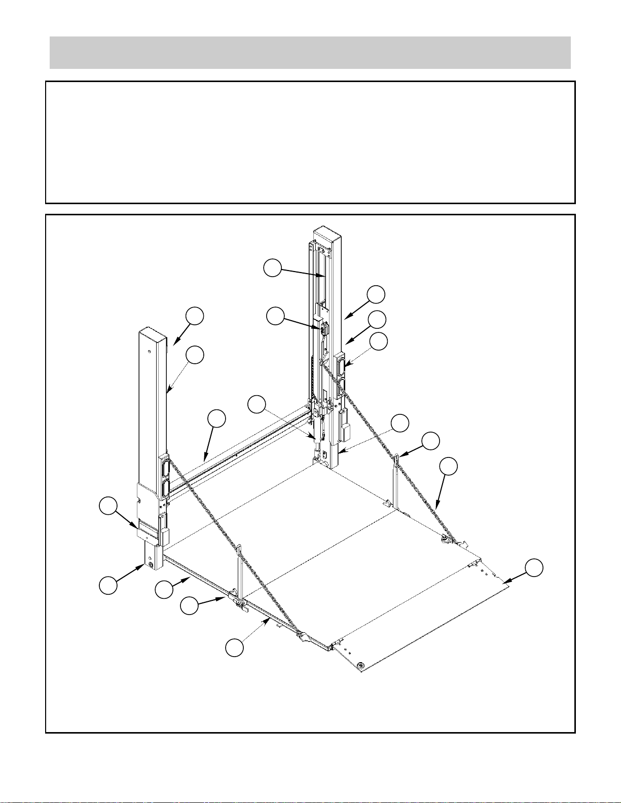
LIFTGATE TERMINOLOGY........................................................................................................................4-7
HYDRAULIC CIRCUIT DIAGRAM ..............................................................................................................8
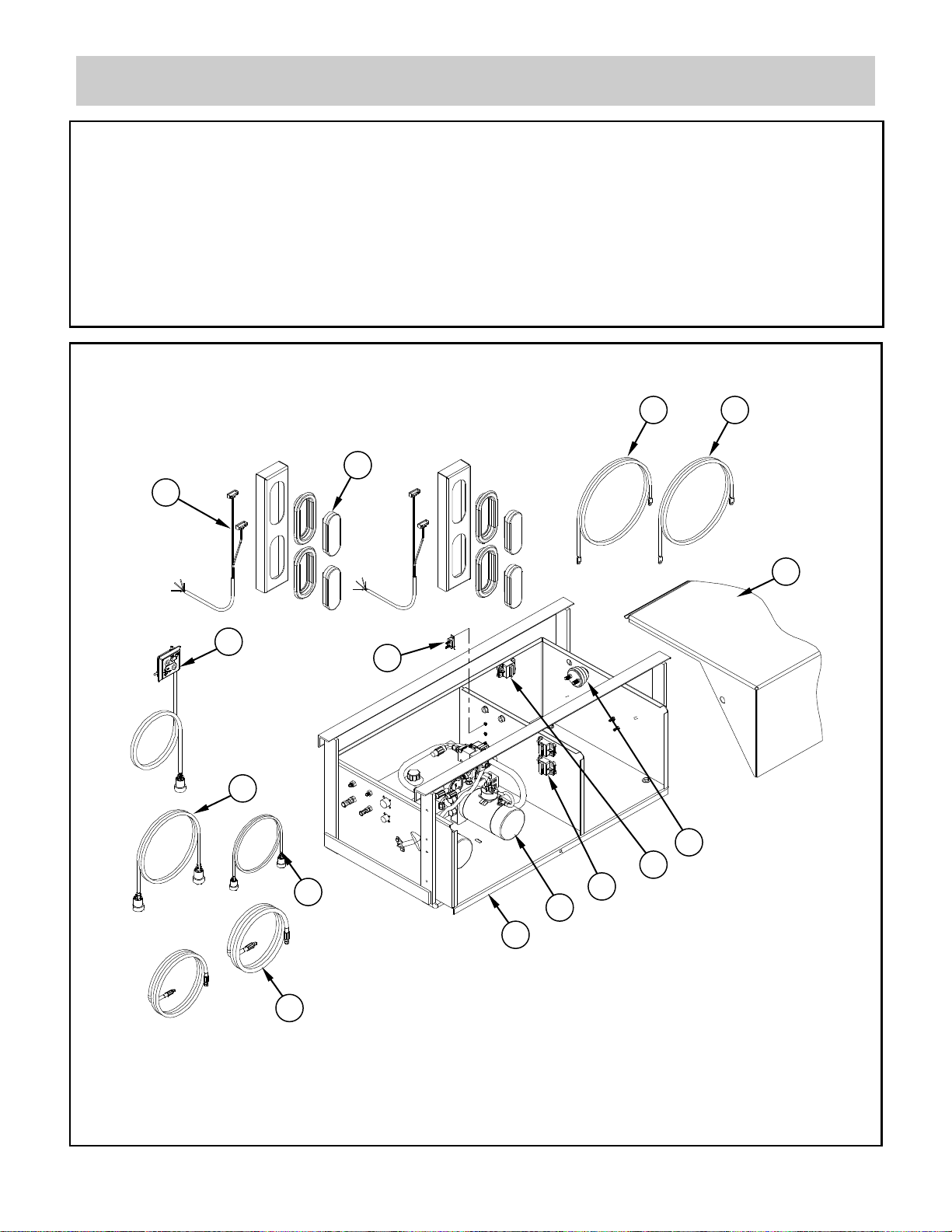
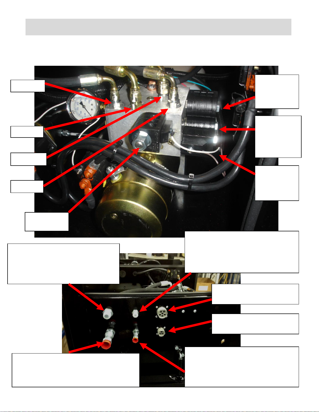
POWER UNIT KEY COMPONENTS ...........................................................................................................9-14
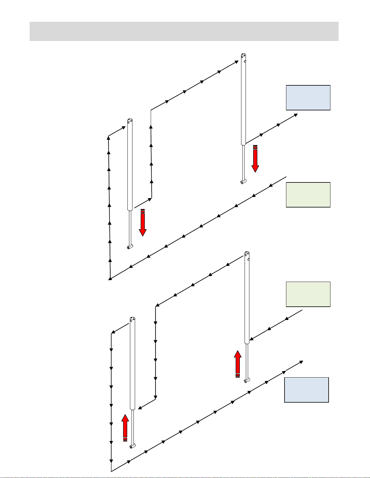
ELECTRICAL & HYDRAULIC FLOW SCHEMATICS ................................................................................15-18
HYDRAULIC & ELECTRICAL SCHEMATICS BUILT FROM 4/09 THRU 10/11 .......................................19-20
HYDRAULIC & ELECTRICAL SCHEMATICS BUILT FROM 10/11 ..........................................................21-22
HYDRAULIC & ELECTRICAL SCHEMATIC - WORK LIGHT....................................................................23
HYDRAULIC & ELECTRICAL SCHEMATICS – CYCLE COUNTER.........................................................24-25
HYDRAULIC & ELECTRICAL SCHEMATIC- GRAVITY DOWN ON DEMAND ........................................26-27
HYDRAULIC & ELECTRICAL SCHEMATIC ..............................................................................................28-31
TROUBLESHOOTING GUIDE ....................................................................................................................32-36
LIFT CYLINDER REPLACEMENT INSTRUCTION....................................................................................37-38
CLOSING CYLINDER BLEEDING PROCEDURE......................................................................................39
HYDRAULIC OIL CHANGING PROCEDURE ............................................................................................40
HIGH PITCH NOISE REPAIR......................................................................................................................41
REPLACING SWITCH AND POWER CLOSE HOSES ..............................................................................42-43
TRAVEL LATCH ENGAGMENT .................................................................................................................44
PREVENTIVE MAINTENANCE...................................................................................................................45-46
HOW TO ORDER PARTS............................................................................................................................47
2

Introduction
Each Waltco liftgate is manufactured to stringent quality standards for years of reliable
service. To ensure maximum performance of your Waltco liftgate, always specify and use
“OEM Parts” from Waltco.
This manual does not provide procedures for the servicing and repair of Waltco liftgates.
Service and repair should only be performed by an authorized Waltco distributor. For
information on the nearest authorized Waltco distributor contact:
Waltco Lift Corp.
285 Northeast Avenue
Tallmadge, OH 44278
Phone: 800.411.5685
Fax: 800.411.5684
E-mail: parts@waltco.com
The use of non-standard or makeshift parts can be extremely hazardous and result
in serious injury or death.
Every vehicle that has a WALTCO Liftgate must have legible WARNING AND
OPERATION DECALS clearly posted on the vehicle and an OWNER’S MANUAL in
the vehicle at all times as a guide for proper operation and maintenance.
Improper operation and maintenance of this liftgate could result in severe
personal injury or death.
Read and understand the contents of the owner’s manual and all warning and
operation decals before operating and/or performing maintenance on this
liftgate.
This is the safety alert symbol. This manual uses this symbol to alert you to
potential personal injury hazards. Obey all safety messages that follow this symbol to
avoid personal injury or death.
3

Liftgate Terminology
1. Street Side Upright
2. Curb Side Upright
3. Lights
4. Inside Switch
5. Sill Extension
6. Support Chain
7. Chain Linkage Bar
8. Bottom Stop Catch
9. Main Deck
10. Deck Extension
11. Folding Ramp
12. Street Side Runner
13. Curb Side Runner
14. Control Switches
15. Closing Cylinder
16. Street Side Lift Cylinder
17. Curb Side Lift Cylinder
18. Specification Tag
19. Dock Bumper
-
2
3
15
13
10
5
6
7
11
4
8
9
12
19
14
18
16
17
4

Liftgate Terminology
20. Control Switch
21. Light Wiring Harness
22. Lights
23. Control Switch Extension Wires (Optional)
24. Inside Switch Extension Wires (Optional)
25. Extension Hoses (Optional)
26. Circuit Breaker, 15A Control Switches
27. Power Unit Motor
28. Charging Battery Cable
29. Grounding Battery Cable
30. Power Unit/Battery Box
31. Box Cover
32. Master Disconnect
33. Circuit Breaker, Charge Line
34. Circuit Breakers,150A
GR02360
20
31
21
22
29
28
32
33
34
27
30
25
23
24
26
5

Liftgate Terminology
35. Side Rail Assembly
36. Outer Guard Rail Assembly
37. Guard Rail Latch Assembly
38. Inner Guard Rail Assembly
39. Ramp Assembly
40. Gas Bottle Retention Chain
WDVBG
GR02366
35
36
37
39
38
40
6

Liftgate Terminology
EXPLANATION OF SPECIFICATION TAG
MODEL No.
DESCRIPTION
CAPACITY
WDVBG45
WDVBG-45 Series
4500 lb.
WDV35
WDV-35 Series
3500 lb.
WDV45
WDV-45 Series
4500 lb.
WDV55
WDV-55 Series
5500 lb.
WDV66
WDV-66 Series
6600 lb.
MODEL NUMBER
RATED CAPACITY
Based on an evenly
distributed load on the
platform flat surface
SERIAL NUMBER
of Liftgate. To be used
when ordering parts or
when contacting Waltco
for service or warranty.
DATE OF
MANUFACTURE
MONTH/YEAR
GR00053
7

Series Hydraulic Circuit Diagram
Oil Flow Out
From Pump
Oil Flow Out
From Pump
Oil Flow in
Back to Tank
Oil Flow in
Back to Tank
Series hydraulic
circuit diagrams
Oil is pumped into one
cylinder, and the oil
displaced from the
other end feeds the
second cylinder. When
platform is at floor
level, the oil bypasses
to the tank and the
platform always self
levels to the floor.
Note: Left side cylinder
is larger than right side
cylinder.
How the Series Hydraulics works
8

Pressure
gauge
15 amp Auto
Reset Switch
Backup Switch
Primary Power Unit
Call out of MTE Main & Auxiliary Power Unit
Motor Solenoid
Motor selector switch
Backup Power Unit
Motor Solenoid
RV4-Down
500 psi
RV3-Open
1500 psi
RV2-Up-Close
2800 psi
Key Components
9
For General 1 liftgates

Key Components
A - Close
D - UP
C- Down
B- Open
S4- White
(Lock Valve)
S3- Green
4W2P
Lowering
(Top Back)
S1- Red
3W2P
Selector POC
(Bottom
Back)
S2- Brown
4W2P POC
(Lower
Front)
Platform Raise (Up)
Hydraulic Connection
Connect to bottom port on Curb Side
Cylinder and “D” Port marked on the
pump.
Platform Lower (Down)
Hydraulic Connection
Connect to top port on Driver Side Cylinder
and “C” Port marked on the pump.
Hydraulic Power Open Hydraulic
Connection
Connect to top port on Power Close
Cylinder and “A” Port marked on
pump.
Hydraulic Power Close Hydraulic
Connection
Connect to Bottom port on Power
Close Cylinder and “B” Port marked
on pump.
Column Switch Point
Connection
External Double Toggle
Switch Point Connection
Call Out of Main & Auxiliary Power Unit Continued
10

Pressure
gauge
15 amp Auto
Reset Switch
Backup Switch
Primary Power Unit
Call out of Bucher Replacement Main & Auxiliary Power Unit
Motor Solenoid
Motor selector switch
Backup Power Unit
Motor Solenoid
RV4-Down
500 psi
RV3-Open
1500 psi
RV2-Up-Close
2800 psi
Tank
Tank
Ground
Ground
150 amp
Circuit Breaker
Pilot Activated
Check Valve
Key Components
11
All Generation 2 models
will have the Bucher units

A - Close
D - UP
C- Down
B- Open
SV4- White
(Lock Valve)
SV3- Green
4W2P
Lowering
(Top Back)
SV1- Red
3W2P
Selector POC
(Bottom
Back)
SV2- Brown
4W2P POC
(Lower
Front)
Platform Raise (Up)
Hydraulic Connection
Connect to bottom port on Curb Side
Cylinder and “D” Port marked on the
pump.
Platform Lower (Down)
Hydraulic Connection
Connect to top port on Driver Side Cylinder
and “C” Port marked on the pump.
Hydraulic Power Close Hydraulic
Connection
Connect to top port on Power Close
Cylinder and “A” Port marked on
pump.
Hydraulic Power Open Hydraulic
Connection
Connect to Bottom port on Power
Close Cylinder and “B” Port marked
on pump.
Column Switch Point
Connection
External Double Toggle
Switch Point Connection
Call Out of Bucher Replacement Main & Auxiliary Power Unit Continued
Key Components
12

Pressure
gauge
15 amp
Auto Reset
Switch
Fuse
Backup Switch
Primary Power Unit
Call out of Generation 2 Main & Auxiliary Power Unit with Divorced Manifold
Auxiliary Motor
Solenoid
Motor
selector
switch
Auxiliary Power Unit
RV4-Down
500 psi
RV3-Open 1500 psi
(backside of manifold)
RV2-Up-Close 2900 psi
(underside of manifold)
Auxiliary
(back –up)
Alarm
Ground
150 amp
Circuit
Breaker
Pilot Activated
Check Valve
Primary Motor
Solenoid
Tank Fill Cap
Relays
Thermal
Switch
Wires
Key Components
13

A - Close
D - UP
C- Down
B- Open
SV4- White
(Lock Valve)
SV3- Green
4W2P
Lowering
(Front Left)
SV1- Red
3W2P
Selector POC
(Front Right)
SV2- Brown
4W2P POC
(Lower
Front)
“D” Port - Platform Raise
(Up) Hydraulic Connection.
Connect to bottom port on
Curb Side Cylinder.
“A” Port - Hydraulic
Power Close Hydraulic
Connection.
Connect to top port on
Power Close Cylinder.
Column Switch Point
Connection
External Double Toggle
Switch Point Connection
Call Out of Generation 2 Main & Auxiliary Power Unit Continued
“C” Port - Hydraulic Lower
(Down) Connection.
Connect to top port on
Driver Side Cylinder..
“B” Port - Hydraulic Power Open
Hydraulic Connection.
Connect to Bottom port on
Power Close Cylinder.
Check
Valve
P1- Pressure Line
From Aux. Pump.
P- Pressure Line
From Primary Pump.
T – Return
Line to Tank
Key Components
14

Electric / Hydraulic Flow Schematics
Power Up
S4 Valve/Coil activated for Up function
15

Electric / Hydraulic Flow Schematics
Power Down
S3 & S4 Valve/Coil activated for the Down
function
16

Electric / Hydraulic Flow Schematics
Power Close
S1 Valve/Coil activated for the Close function
17

Electric / Hydraulic Flow Schematics
Power Open
S1 & S2 Valve/Coil activated for the Open function
18

Electric / Hydraulic Schematics
Built from 4/09
thru 10/11
Single pump
Motor
Single Relay
19

Electric / Hydraulic Schematics
Built from 4/09 thru 10/11
Dual Pump Motor with
Back Up/Auxiliary
Single Relay
20
This manual suits for next models
1
Table of contents
Other WALTCO Lifting System manuals
Popular Lifting System manuals by other brands

Eagle Equipment
Eagle Equipment MTP-11V3 Installation & operation manual

Upright
Upright X20N Operator's manual

Thunderstone
Thunderstone Thunder Power Tarp 6000XR Series Operation instructions

TECNA
TECNA 9502RL instruction manual

ShoreStation
ShoreStation SSV30108EDC Service manual

Rotary
Rotary MASTER GEAR MGE 2.0 Operation & maintenance manual