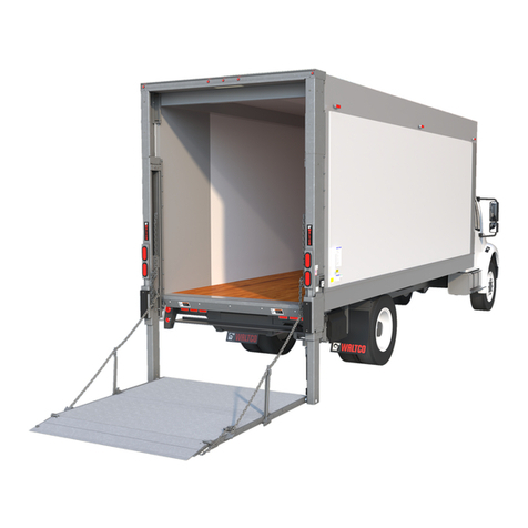
WALTCO GT-33 User manual

80127801
Installation Manual
GT-33, 44, 55
3300, 4400, 5500 lb. Capacity Flipaway Liftgates
Last Change:
Date Pages Description
01-2022 ALL Updated mounting requirements and line drawings
Waltco Lift Corp.
Corporate Office United States
1777 Miller Pkwy
Streetsboro, OH 44241
P: 330.633.9191
F: 330.633.1418
EO:10848 Rev 03
01-2022
www.waltco.com Phone: 800.411.5685
parts@waltco.com Fax: 800.411.5684

Table of Contents
Introduction .....................................................................................................................3
1. Safety Information................................................................................................................ 4
2. Liftgate Terminology ............................................................................................................ 6
3. Basic Mounting Requirements ............................................................................................. 8
4. Installation ..........................................................................................................................11
5. Placement of Decals...........................................................................................................29
6. Lubrication Instructions .......................................................................................................32
7. Final Inspection...................................................................................................................33
8. How to Order Parts .............................................................................................................34
9. Optional Kit Instructions:
Hand Held Remote Kit.......................................................................................................35
Kit #80001433
Aux Battery Kits (Trailer) ...................................................................................................36
Improper installation of this liftgate
could result in severe personal injury or
death.
Read and understand the contents of these instructions before proceeding.
When installed, this liftgate must not alter or prevent vehicle compliance to any
existing state or federal standards.
Each chassis manufacturer’s recommendations should be consulted for
compliance.
2

INTRODUCTION
If anyone observes improper installation, improper operation, or damage, they should immediately
contact a qualified person for assistance and correction. We strongly urge anyone that has any questions
or doubts as to the installation, condition, use, operation, maintenance or repair of the liftgate to contact
us at Waltco where we have qualified personnel that will be happy to assist you. Telephone numbers and
addresses of these locations are listed in the Owner’s Manual and Installation Instructions.
INSTALLATION
Waltco liftgates should only be installed by those with sufficient basic skills to understand the
installation and operation of the liftgate, along with the equipment on which the liftgate is being installed.
Waltco’s installation instructions are not intended to give rationale for all the instructions that are given;
however, it is the intent of these instructions to give the installer both the operations and what we believe
to be the most desirable sequence of implementing these operations. These instructions can in no way
expand into an area where they will replace a qualified person, or clear thinking and a basic knowledge
that must be possessed by the installer.
It has been our experience that a knowledgeable journeyman following these instructions and
observing the operation of the liftgate will have a sufficient comprehension of the liftgate to enable this
person to troubleshoot and correct all normal problems that may be encountered.
Failure to follow the installation instructions, adjustments and mounting dimensions may result in
improper and unsafe operation of the liftgate. Unauthorized alterations of the liftgate can cause an
undesirable and dangerous condition.
OWNER’S MANUAL
The Waltco Owner’s Manual is intended to act as a guide for operation and routine maintenance but
is no way intended to encourage usage or repair of the liftgate by those who are not qualified to do so.
The contents of the owner’s manual include, but are not limited to general operation instructions,
routine lubrication, parts lists, and an outline of things that should be checked but may not be obvious to
those not technically qualified. This manual assumes the liftgate is properly installed, undamaged and
operates correctly. Improper installation, improper operation, or damage should be immediately corrected
by a qualified person.
INSPECTION
As part of the regular inspection of a liftgate and after damage or suspicion of an overload, inspect for
wear or structural damage and make necessary repairs or replacements. Check all structural components
and their attachment to the liftgate for cracked welds, loose fasteners, wear and part deformation. Check
cylinder and hose for leaks. Inspections and repairs should be made by a qualified mechanic.
REPLACEMENT PARTS
Use only Waltco original equipment replacement parts. Components of other liftgate manufacturers
may outwardly appear to be the same but are not interchangeable with Waltco products. Waltco
components are specifically designed for safety requirements, reliability and compatibility with our
products. Refer to your Waltco parts manual when ordering parts. NOTE: When ordering, give model and
serial number of liftgate.
DECALS
It is important that every vehicle that has a WALTCO Liftgate have legible DECALS clearly posted on
the vehicle and an OWNER’S MANUAL in the vehicle at all times as a guide for proper operation and
maintenance.
Additional DECALS and OWNER’S MANUALS can be obtained from WALTCO LIFT CORP.
80101388 Rev 0
3 EO 7820
3

Chapter 1 Safety Information
80101253 Rev 04 EO 6309JJ
WARNING
Read, understand, and follow all of the warning listed below.
Failure to follow these warning could result in severe personal injury or death.
• Read and understand the Owner’s Manual, all decals and warning on liftgate before operating liftgate.
• Do not operate liftgate without a thorough knowledge and understanding of the operation of the liftgate.
•Liftgate hazards can result in crushing or falling.
•This liftgate is designed for loading and unloading of cargo. If personnel are required to ride liftgate, observe
and familiarize yourself with the liftgate operation, decals and manuals. Ensure stable footing at all times.
•Do not ride liftgate with unstable loads.
•Wheeled loads must be properly retained from rolling.
•Tall, high center of gravity loads must be retained from falling over.
•Never overload liftgate:
Load platform as close to the vehicle, and towards the middle of the platform as possible. Refer to owner’s
manual and capacity decal of liftgate for maximum load and load placement.
•Keep hands and feet clear of all potential pinch points.
•Never use liftgate if it makes any unusual noise, has unusual vibration, raises or lowers unevenly, or fails to
operate smoothly.
•Never use liftgate if it shows any signs of structural damage such as cracked welds, bent or distorted
members.
•Do not attempt any repairs unless you are qualified to do so. Care should be taken when work is performed
on a disabled liftgate located near moving traffic. When possible the vehicle should be moved away from
traffic areas for repair. Precautionary measures should be taken to ensure personal safety including those
recommended in Federal Motor Vehicle Safety Standards 571.125.
•When welding to liftgate, or liftgate components, take all necessary safety precautions, including using
respiratory protection and other pertinent personal protective gear when welding harmful materials.
• All protective covers, guards, and safety devices must be in place and access doors closed before operating
liftgate.
•Do not allow anyone to stand in, or near area, in which Platform will open and close before opening or closing
Platform.
•Do not allow anyone to stand near the Platform where a falling load could land on them.
•Platform is always to be properly stored and secured for transit. See the Owner’s Manual for details.
•Take care to retain cargo during transit for liftgate Platforms which function as the tailgate or door of the cargo
area. Small objects can fall through the space between the vehicle and the folded Platform.
•A Lock-Out device or Shut-Off Switch should always be used to prevent unauthorized use of liftgate.
•For liftgates with Runners, never use liftgate if Runners do not travel freely and smoothly.
•For liftgates with Roller Lifting Chain, the Chain should be replaced every (5) five years or 15,000 cycles,
whichever comes first. Replace only with Waltco approved Roller Chain.
•Never transfer loads which exceed lifting capacity on or over any part of the Platform unless the liftgate is
equipped with a special reinforced Platform and Platform Support Bars for use when the Platform is used as
loading ramp (dock board). Refer to the “Using Platform as a loading ramp” Chapter in the Operation
Instructions of the BZ/RZ series Owner’s Manual.
•For liftgates equipped with Trailer Hitches, never exceed the rated capacity of the hitch. Do not exceed the
vehicle’s weight rating. Refer to the vehicle’s Owner’s Manual.
•Vehicle must comply with all state and federal standards.
•Follow the “Maintenance Guide” chapter in the Owner’s Manual.
4

Chapter 1 Safety Information
80101253 Rev 04 EO 6309JJ
Liftgates with Tilt Function
•Proper use of the Control Switches is of extreme importance.
•Improper use of Tilt Switch could cause load to fall from the Platform or damage the liftgate.
•Platform should be in a generally horizontal position when raising or lowering with a load.
•In any tilt position, the Platform may vary from level while raising or lowering the Platform.
Liftgates equipped with spring operated Cam Closer
•Replace Cam Release Spring every five (5) years or 15,000 cycles, whichever comes first.
RGL-Series Liftgates
•Make certain Platform Brake mechanisms are operating properly.
•The Runners are always to remain powered up against the Upstops Pins when in transit.
•Inspect Cables every three (3) months or 750 cycles, whichever comes first. Cables must be replaced if they
show signs of wear, distortion, kinking or if any broken wires are visible
•Replace cables every five (5) years or 10,000 cycles, whichever comes first.
This is the safety alert symbol. This manual uses this symbol to alert you to potential personal injury
hazards.
Obey all safety messages that follow this symbol to avoid personal injury or death.
SIGNAL WORDS
WARNING
Indicates a potentially hazardous situation, which if not
avoided, could result in death or serious injury.
Black letters on an orange background
CAUTION
Indicates a potentially hazardous situation, which if not
avoided, may result in minor or moderate injury. May
also be used to alert against unsafe practices.
Black letters on a yellow background.
NOTICE
Indicates a potentially hazardous situation, which if not
avoided, may result in property damage.
NOTICE
WARNING
CAUTION
5

Chapter 2 Liftgate Terminology
1. Deck 10. Pump unit
2. Deck extension 11. Spec tag (Includes serial number)
3. Retention ramp 12. Switches
4. Platform Handle 13. Mount Frame
5. Mount tube 14. Mount angles
6. Lift cylinder 15. Platform Pin (Torsion springs hidden behind guards)
7. Lift arm
8. Parallel arm
9. Pump & Battery box
GR10134
6

Chapter 2 Liftgate Terminology
EXPLANATION OF SPECIFICATION TAG
MODEL NO. DESCRIPTION CAPACITY
GT33 GT-33 SLIDER LIFTGATE 3300 LBS.
GT44 GT-44 SLIDER LIFTGATE 4400 LBS.
GT55 GT-55 SLIDER LIFTGATE 5500 LBS.
GR00241
SPEC TAG
7

Chapter 3 Basic Mounting Requirements
TRAILER WIDTH
GT-33/44/55 liftgates are designed for 96-102” wide
trailers.
IMPORTANT! Do not exceed maximum width of vehicle
under any circumstances.
GR10129
GR10130
DETERMINE MOUNTING DIMENSIONS
NOTE: Measure all dimensions when trailer is
unloaded and on a flat horizontal surface.
1. Determine the Bed Height. Measure from
top of trailer floor down to ground level.
2. Determine “A” dimension = Bed Thickness.
Measure from top of trailer floor to bottom of
the trailer’s cross members.
3. Determine Sill depth.
GR10131
TOP VIEW OF TRAILER
8

Chapter 3 Basic Mounting Requirements
GR10132
9

Chapter 3 Basic Mounting Requirements
INSTALLATION WEIGHT
Make sure that trailer is capable of supporting liftgate
forces when liftgate is in stored position and when
liftgate is loaded to full capacity.
Note that forces shown here are in pounds and are
distributed over two liftgate rails.
GT- 33
GT- 44
GATE STORED
GATE
DEPLOYED
GT- 55
1,000
800
10,500
6,000
13,000
7,500
16,000
9,000
10

Chapter 4 Liftgate Installation
CONNECT BATTERIES
Connect Positive Cable inside Battery Box to positive
terminal on Battery via Circuit Breaker as shown. Studs
on Circuit Breaker are labeled BAT and AUX. Connect
Battery Stud to Bat Terminal and Battery Cable to Aux
Terminal. Connect Ground Cable as shown.
Make sure that Batteries are secured tightly.
Note! Add dielectric grease to all Connectors.
NOTE! Make sure Batteries are fully charged and
connected before moving Liftgate underneath Trailer!
PREPARATION OF BODY
Remove all obstructions that will interfere with Liftgate
mounting or operation.
Bumper or Under Ride Guard
License Plate
Mud Flaps
Other projections
Move Slide-Axles forward if necessary to attain required
(liftgate) Mount Frame Clearance. This dimension is
found in Installation Dimensions.
Determine where new full length mud flap (provided) will
attach. Should be as close to wheels as possible. Do
not mount at this time.
Req'd Liftgate Mount
Frame Clearance
GR01256
Mud Flaps
Ground Cable
Positive Cable
Be certain Wires are protected from any
sharp edges or holes that may abrade
insulated covering of Wires
Do not connect any other wires at this
time.
Make sure that Trailer Cross Members are
relatively straight and can support forces
from Liftgate. It may also be necessary to
remove extensive rust or anti-rust
protection from Cross Members to have a
good surface for welding.
GR10133
11

Chapter 4 Liftgate Installation
CHECK BOLTING LOCATION
Ensure that the Track is in the proper starting location.
Check page 9 for the proper Hole Column Number.
Track should be positioned such that the slot shown
circled at right bolts into the correct Hole in the Mount
Plate.
If the slot is in the wrong hole location, remove Mount
Bolts and position Mount Plates correctly. Reinstall
Mount Bolts and temporarily torque tight.
GR02617
LIFTING THE GATE
Always lift gate up from shown position (under 4”
channels).
NOTE: Set forks to widest width possible to avoid
bowing of 4” channels.
Use fork extensions if needed.
NOTE: Failure to lift gate up according to instructions
can damage the gate.
Lift up from here
4” Channel
During the final positioning adjustments, Hole
Column Number may change depending on
Rear Sill configuration. Never change Hole
Row Letter as this may take Liftgate out of
Canadian Underride compliance.
Adjust holes in slots such that both mount
plate rear edges are in
same position relative
to rear edge of liftgate track
Rear Edges
12

Chapter 4 Liftgate Installation
ALIGNING LIFTGATE WITH TRAILER
Align liftgate to be centered with Trailer.
Lift the gate up and move underneath Trailer.
Lift the gate up against the Trailer’s Cross Members.
Continue to move the Liftgate forward (underneath)
Trailer until the 6” dimension shown is achieved. This
dimension is measured from rear of Mount Plate to the
back of Rear Sill (do not include misc. hardware such as
“Eyebrows” or Door Locks in measurement). Checking
6” dimension in (2) places will assist in getting Liftgate
square with the Rear Sill.
Note! Usually Liftgate can be aligned only to a certain
degree with a forklift truck. After that, final adjustments
usually require such tools as a crowbar and rubber
mallet.
Note! Verify Liftgate is square and properly aligned
before tack welding in position.
GR01480 & GR10143
It is important that the Liftgate be centered
and aligned square to Rear Sill only! Allow
the rear of Liftgate to float.
13

Chapter 4 Liftgate Installation
TACK WELD THE GATE
Weld Mount Angles to Cross Members as shown from
both sides (4 plcs).
GR0
2619
POSITION PLATFORM
Push Lower Switch to lower Platform from storage
position.
Do not lower Platform to ground level, lower just enough
to clear Storage Stops.
Push Open Switch to move Platform to working position.
Lower Platform to ground.
Open Platform Extension and Loading Ramps manually.
Note! Use handle to open Platform Extension.
GR01233
HANDLE
Trailer’s cross
members
Weld parallel to Cross Members, along the
top of the Mounting Angles. Never
perpendicular to the Cross Members, as
structural damage to Trailer could result.
Do not go underneath of Liftgate or
Platform before the Liftgate is fully welded!
Always make certain area in which Platform
will open is clear.
14

Chapter 4 Liftgate Installation
Raise Platform almost to bed level.
Note! Liftgate has not yet been aligned. Be careful not to
hit Trailer with Platform.
PLATFORM NOTCHING
It is usually necessary to notch Platform in order to
prevent it from hitting the Trailer Door Hardware. It may
be necessary to move the platform upstops to prevent
them from hitting Trailer Door Hardware. Do not
remove, just move them to a new location that does not
interfere with Trailer Door Hardware.
Measure for required notches, cut and re-paint.
Note! Max. notch depth is 2-7/8”
GR01274
FINE TUNING PLATFORM POSITION
Platform Edge must align with Rear Sill as shown (just
over Rear Sill Radius allowing upstops to contact the
Rear Sill).
If Platform is hitting Rear Sill too low:
Loosen Mounting Bolts from Mount Plates (12 plc’s).
Pull liftgate out as much as needed.
Approximately 1” out will raise platform 1”.
Test that platform aligns properly.
Tighten all Mount Bolts (12 plc’s) to 80 ft-lbs.
If Platform is hitting Rear Sill too high:
Loosen Mounting Bolts from Mount Plates (12 plc’s).
Push Liftgate in as much as needed.
Approximately 1” in will lower platform 1”.
Test that Platform aligns properly.
Tighten up all bolts (12 plc’s) to 80 ft-lbs.
It is important that both sides of Liftgate be adjusted in or
out by equal amounts. Adjusting one side more than the
other may result in the Liftgate binding when running
Liftgate in or out of the stored position.
REAR SILL RADIUS
MOUNTING BOLTS
2
PLATFORM UP-STOP
15

Chapter 4 Liftgate Installation
FINAL WELDING OF MOUNT ANGLES
Test that the Liftgate will move in and out before final
welding of Mount Angles.
Make all final welds to Mounting Angles and Trailer as
shown.
Note! Weld one section at time and then opposite side
to prevent welds from distorting Mount Track.
Note! If trailer has forklift reinforced rear sill, welds may
be perpendicular to the formed channel cross member.
GR01265
INSTALL TRAILER MOUNTING ANGLE SUPPORTS
For GT-33/44:
Trailer’s I-beams will need to be re-enforced in six (6)
places with the supplied flat bar (3 on each side).
Supplied flat bar is 60” long and will need cut down to fit
in between trailer I-beams. Shown to the right, (2) of
these reinforcements will be positioned closest to the
rear of the trailer. The other bar is located between
trailer I-beams at the rearmost part of the liftgate as
shown.
Bar supports are positioned flush with the mount angles.
Weld ¼” fillet to each vertical web of each I-beam.
For GT-33/44:
Use remaining flat bar and cut (4) additional strips, at
least 6” long each, to connect the liftgate to
reinforcement strips as shown in blue.
Weld (2) bars per side as shown to the right with ¼”
fillet all around on each bar. (1) at the front of the
liftgate & (1) at the rear of the liftgate.
Weld parallel to Cross Members, along top
of Mounting Angles. Never perpendicular to
I-beam shaped Cross Members, as
structural damage to the Trailer could
result.
FLUSH
REAR OF TRAILER
FRONT OF LIFTGATE
16

Chapter 4 Liftgate Installation
INSTALL TRAILER MOUNTING ANGLE SUPPORTS
For GT-55:
Trailer’s I-beams will need to be re-enforced in ten (10)
places with the supplied flat bar (5 on each side).
Supplied flat bars are 60” long and will need cut down to
fit in between trailer I-beams. Shown to the right, (8) of
these reinforcements will be positioned closest to the
rear of the trailer and flush with mount plate edge.
The other (2) bars are located between trailer I-beams
at the rearmost part of the liftgate as shown.
Bar supports are positioned flush with the mount
angles. Weld ¼” fillet to each vertical web of each I-
beam.
For GT-55:
Use (8) provided angles and (2) remaining flatbars to
connect the liftgate to reinforcement strips as shown in
blue.
Weld bars and angles (10X total) as shown to the
right with ¼” fillet all around on each part. (8) angle
reinforcements at the front of the liftgate & (2) at the
rear of the liftgate.
SECURING WELDS
Weld OR bolt Track Frame to Mount Angles as shown.
Note! Bolt Mount Plate to Track Frame with 9/16” Shear
Bolt if easy Liftgate removal is desired. This requires a
9/16” hole through the Track Frame an existing Mount
Plate hole and insert a 9/16” shear bolt.
GR0
2618
REAR OF TRAILER
FRONT OF LIFTGATE
17

Chapter 4 Liftgate Installation
INSTALL FULL LENGTH MUDFLAP
Sandwich the 30” x 100” Mudflap (provided) between the
100” Angle and 100” Flatbar (provided), with the bolts
and hardware (provided). Install the full length Mudflap
as close to the wheels as possible. If trailer is 96” wide,
the Mudflap must be cut-down 6”.
IMPORTANT: Failure to install full length
mudflap voids warranty on pump box
components and hydraulic cylinders.
CHECK THE LIFTGATE OPERATIONS
Check that Liftgate operates freely and smoothly, and
that there are no unusual noises or vibrations.
Run all movements several times to remove any air from
hydraulic system.
GR01242
INSIDE SWITCH
Drill hole (1” dia.) for cable in trailer floor.
Weld inside switch to corner post as shown.
Route cable to pump unit box and connect to pump units
wiring harness by matching connectors and by
grounding white wire.
Make sure that cable doesn’t pinch when gate moves.
Use wire ties to secure cable.
CHECK OIL LEVEL
See chart below for proper platform position for oil
check.
Oil level should be within ½” to fill line (over or above)
marked on the side of Oil tank.
Fill as may be required
Follow oil recommendations.
ROUTE CABLES
THROUGH FLOOR
18

Chapter 4 Liftgate Installation
LIFTGATE POSITION FOR OIL LEVEL CHECK
Deck should be in this position:
Gravity Down Pump: Power Down Pump:
Lowered to Ground Level Raised to Bed Level
Recommended Fluids Fill reservoir
Temperature Range Acceptable Fluids •Fill with recommended fluid or equivalent.
0°to 120°F Waltco Biodegradable
LiftlubeTM part #85803860
•Fill the reservoir to within 1/2” from the top.
•Fluids are available from the Waltco parts
Shell Tellus S2 V 32 Dept. 1-800-411-5685 www.waltco.com
Chevron Rando HDZ 32
-20°to 90°F Waltco Biodegradable
LiftLube Arctic part
#85803866
NOTE:
Do not use the following fluids:
Waltco All Season Hyd Oil
Part 85803867
Shell Tellus S2 Vx 15
Mobil DTE 10 Excell 15
Brake Fluid
Power steering fluid
Automatic Transmission Fluid (ATF)
Chevron Rando HDZ 15
Rev 06
FINISH WIRING
For Direct Power kits run the charge line to the single or
dual pole charge plug at the front of the trailer.
For Trail Charger kits run the trail charger cable to the
front of the trailer and follow supplied trail charger
installation instructions.
Establish a good ground between the tractor and trailer
(not through fifth wheel).
19

Chapter 4 Liftgate Installation
ADD DIELECTRIC GREASE TO CONNECTORS
All connectors must be covered with dielectric grease
(not supplied).
Note especially following locations:
Positive battery pole
Control switch cables
GR10133
20
This manual suits for next models
2
Table of contents
Other WALTCO Lifting System manuals
Popular Lifting System manuals by other brands

ALMAC
ALMAC ATHENA 850-BL EVO TRANSLATION OF ORIGINAL INSTRUCTIONS

IDEAL
IDEAL 7000TLX Assembly & operation manual

assfalg-metal
assfalg-metal SAFEBAT SB200 operating manual

Wilo
Wilo DrainLift TMP 32-0,5.1 Installation and maintenance instructions

RUTHMANN
RUTHMANN ECOLINE RS200 Use and maintenance manual

WilTec
WilTec 50790 manual