129905
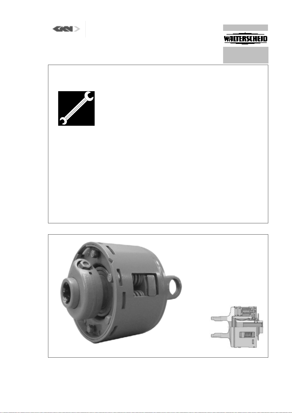
Reib-Freilaufkupplung FK96, FK96/4
Friction and overrunning clutch
Limiteur à friction et roue libre
10
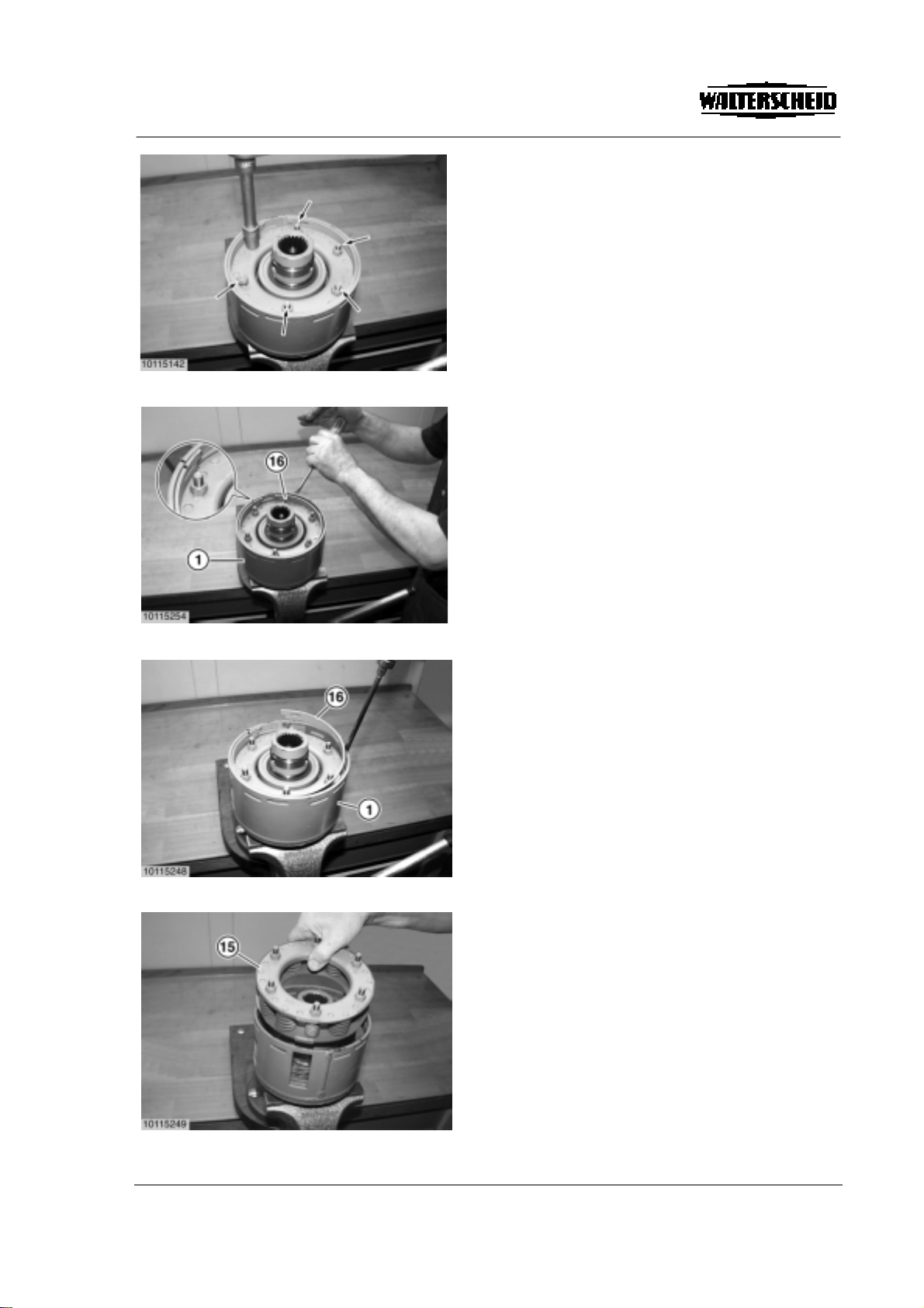
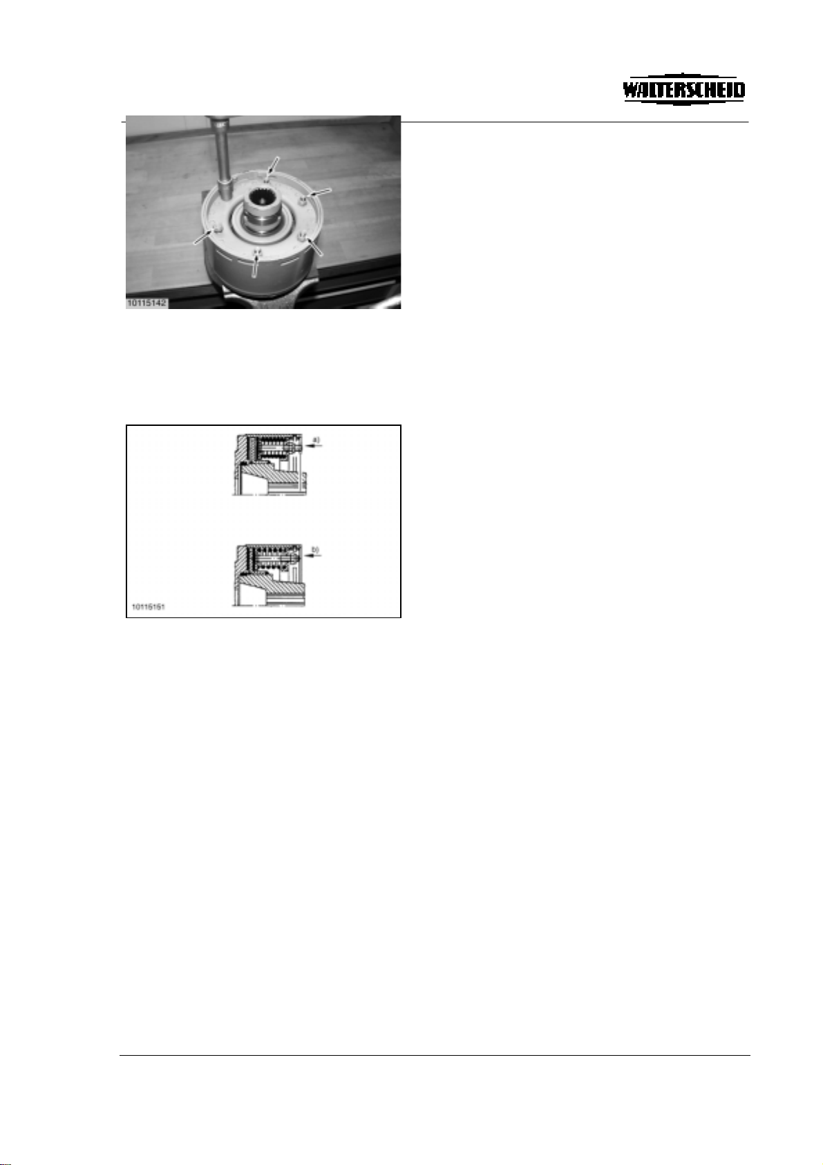
Die sechs Muttern (Pfeile) am Federpaket
abwechselnd (jeweils eine Umdrehung) bis
Gewindeauslauf zurückdrehen. Die Kupplung ist nun
einsatzbereit.
Montage Ziehverschluss siehe Anleitung 129903
Montage CC-Verschluss siehe Anleitung 304991.
Alternately back out the six nuts (arrows) on the
spring pack (one turn at a time) to the end of the
thread. The clutch is now ready for use.
See assembly instructions 129903 for quick-
disconnect lock, ball type.
See assembly instructions 304991 for CC-lock.
Dévisser progressivement les six écrous (flèches) du
bloc-ressort (respectivement d'un tour) jusqu'à la fin
du filetage. L'accouplement est alors opérationnel.
Pour le montage du verrouillage rapide à bille, voir
instruction 129903.
Pour le montage du verrouillage CC, voir instruction
304991.
Achtung!
Vor Ersteinsatz und nach längerer Stillstandszeit
Arbeitsweise der Reibkupplung überprüfen.
a) Muttern anziehen, wodurch Reibscheiben entlastet
werden. Kupplung durchdrehen
b) Muttern bis Gewindeauslauf zurückdrehen
Kupplung ist wieder einsatzbereit.
Caution!
Prior to first use and after long periods out of use,
check working of friction clutch.
a) Tighten nuts until friction disks are relieved. Rotate
clutch fully.
b) Turn nuts fully back.
Clutch is ready for use.
Attention!
Avant la première utilisation et après un arrêt de
fonctionnement prolongé, vérifier le fonctionnement
du limiteur à friction.
a) Serrer les écrous sous lesquels les disques de
friction sont délestés. Tourner le limiteur.
b) Desserrer les écrous jusqu'à l'extrémité du
filetage.
Le limiteur à friction est prêt à fonctionner.