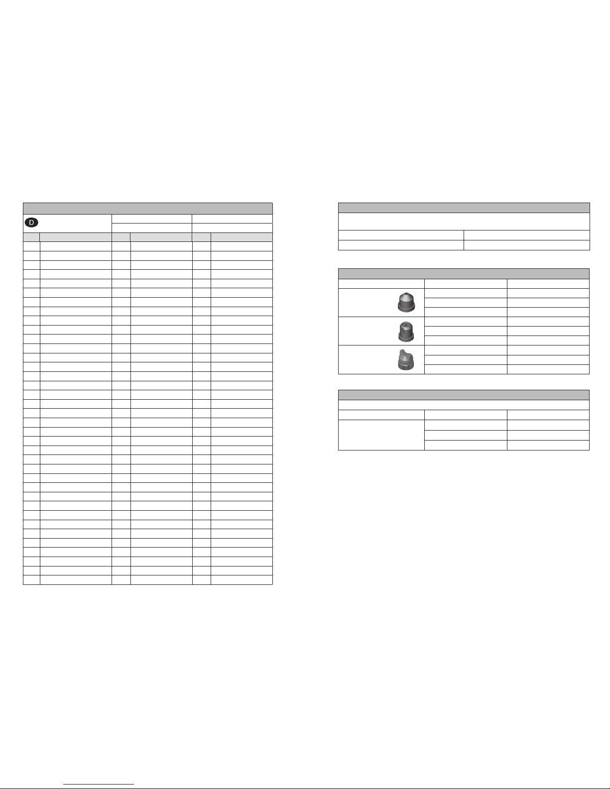
WALTHER PILOT PILOT Signier 20 360 User manual

WALTHER PILOT
Betriebsanleitung / Operating Instructions /
Instructions de Service / Gebruiksaanwijzing
PILOT Signier
Signierpistole / Marking Gun /
Pistolet de Marquage / Markeer Spuitpistolen
Typ / Type
20 360
REV. 10/11
DISTRIBUTED BY COATING EQUIPMENT TECHNOLOGY, INC
PHONE: 586-210-0555
WEB: www.cetinc.com

2
Werkzeug/Tool/Outil/Werktuig für/
for/pour/voor Pos.: 1
V 20 335 28 003
Stand: Juli 2010
PILOT Signier
20 360
8
36
35
9
814
9
PILOT Signier Umlauf
20 361

4
Maßblatt / Dimension Sheet / Mesures / Maataanduiding

Seite 8 - 22
Page 24 - 38
Page 40 - 54
Side 56 - 70

8 9
EG-Konformitätserklärung
Wir, der Gerätehersteller, erklären in alleiniger Verantwortung, dass das Produkt in
der untenstehenden Beschreibung den einschlägigen grundlegenden Sicherheits- und
Gesundheitsanforderungen entspricht. Bei einer nicht mit uns abgestimmten Änderung
an dem Gerät oder bei einer unsachgemäßen Verwendung verliert diese Erklärung ihre
Gültigkeit.
Hersteller WALTHER Spritz- und Lackiersysteme GmbH
Kärntner Str. 18 - 30
D - 42327 Wuppertal
Tel.: +49(0)202 / 787 - 0
Fax: +49(0)202 / 787 - 2217
www.walther-pilot.de • e-mail: [email protected]
Typenbezeichnung Automatische Spritzpistole
PILOT Signier 30 360 V 20 360
Verwendungszweck Verarbeitung spritzbarer Materialien
Angewandte Normen und Richtlinien
EG-Maschinenrichtlinien 2006 / 42 / EG
94 / 9 EG (ATEX Richtlinien)
DIN EN ISO 12100 Teil 1
DIN EN ISO 12100 Teil 2 DIN EN 1953
DIN EN 1127-1 DIN EN 13463-1
Spezifikation im Sinne der Richtlinie 94 / 9 / EG
Kategorie 2 Gerätebezeichnung II 2 G c T 5
Tech.File,Ref.:
2408
Bevollmächtigt mit der Zusammenstellung der technischen Unterlagen:
Nico Kowalski, WALTHER Spritz- und Lackiersysteme GmbH, Kärntner Str. 18 - 30
D- 42327 Wuppertal
Besondere Hinweise :
Das Produkt ist zum Einbau in ein anderes Gerät bestimmt. Die Inbetriebnahme ist so
lange untersagt, bis die Konformität des Endproduktes mit der Richtlinie 2006 / 42 /
EG festgestellt ist.
Wuppertal, den 01. Januar 2010
Name: Torsten Bröker
Stellung im Betrieb: Leiter der Konstruktion und Entwicklung
Diese Erklärung ist keine Zusicherung von Eigenschaften im Sinne der Produkthaftung. Die
Sicherheitshinweise der Produktdokumentation sind zu beachten.
i.V.
Inhaltsverzeichnis
Explosionszeichnung 2
Maßblatt 4
Konformitätserklärung 9
Ersatzteilliste 10
1 Allgemeines 12
1.1 Kennzeichnung des Modells 12
1.2 Bestimmungsgemäße Verwendung 12
1.3 Sachwidrige Verwendung 13
2 Technische Beschreibung 13
3 Sicherheitshinweise 14
3.1 Kennzeichnung der Sicherheitshinweise 14
3.2 Allgemeine Sicherheitshinweise 14
4 Montage 15
4.1 Spritzpistole befestigen 15
4.2 Versorgungsleitungen anschließen 15
5 Bedienung 16
5.1 Sicherheitshinweise 16
5.2 Inbetrieb- und Außerbetriebsetzen 16
5.3 Spritzbildprobe erzeugen 16
5.4 Mängel eines Spritzbildes beheben 17
5.5 Spritzpistole umrüsten 18
6 Reinigung 18
6.1 Sicherheitshinweise 18
6.2 Grundreinigung 19
6.3 Routinereinigung 19
7 Instandsetzung 20
7.1 Undichte Nadelpackung austauschen 20
7.2 Materialdüse, -nadel, Federn und Dichtungen austauschen 21
8 Fehlersuche und -beseitigung 21
9 Entsorgung 22
10 Technische Daten 22

10 11
Reparatursets
WALTHER PILOT hält für die Automatik-Spritzpistolen PILOT Signier und PILOT Signier Umlauf
Reparatursets bereit, die sämtliche Verschleißteile enthalten.
Artikelnummer
PILOT Signier / -Umlauf V 16 120 51 XX3
◄ Luftköpfe wahlweise:
Größe Artikelnummer
Rundstrahlluftkopf 0,3 / 0,5 mm ø V 20 336 34 035*
0,8 / 1,0 mm ø V 20 336 34 085*
1,2 / 1,5 mm ø V 20 336 34 125*
Breitstrahlluftkopf 0,3 / 0,5 mm ø V 20 336 44 032*
0,8 / 1,0 mm ø V 20 336 44 082*
1,2 / 1,5 mm ø V 20 336 44 122*
Breitstrahlluftkopf 0,3 / 0,5 mm ø V 20 336 50 035*
0,8 / 1,0 mm ø V 20 336 50 085*
1,2 / 1,5 mm ø V 20 336 50 125*
Düseneinlagen
Die Düseneinlagen bestehen aus Luftkopf, Materialdüse und Materialnadel
Artikelnummer Luftkopfvariante
PILOT Signier / -Umlauf V 15 120 51 XX3 V 20 336 34 XX5
V 15 120 01 XX3 V 20 336 44 XX2
V 15 120 02 XX3 V 20 336 50 XX5
Düsenausstattung nach Wahl:
0,3 ▪ 0,5 ▪ 0,8 ▪ 1,0 ▪ 1,2 ▪ 1,5 mm ø
* Bei Ersatzteillieferungen bitte entsprechende Größe angeben.
Wir empfehlen, alle fettgedruckten Teile (Verschleißteile) auf Lager zu halten.
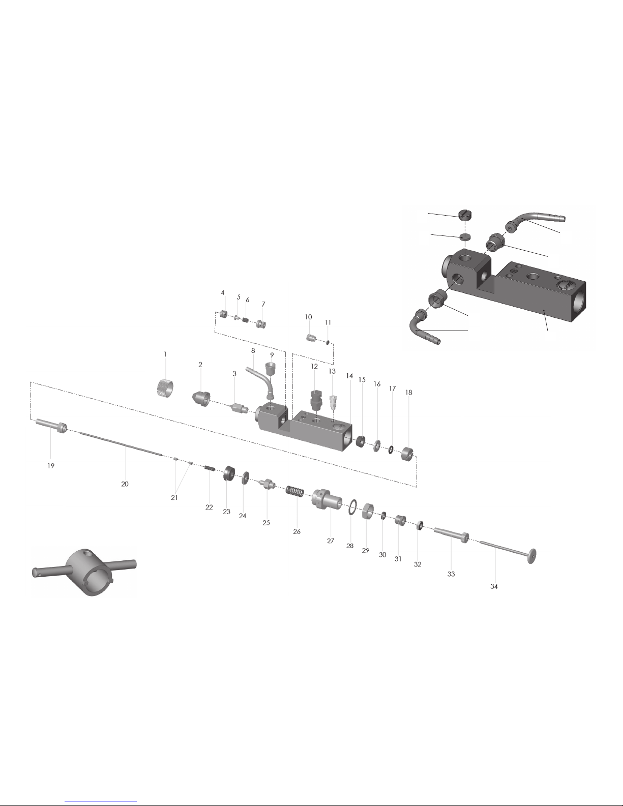
Ersatzteilliste:
Pilot Signier PILOT Signier Umlauf
V 20 360 V 20 361
Pos. Bezeichnung Stck. Artikelnummer Stck. Artikelnummer
1 Überwurfmutter 1 V 20 335 15 000 1 V 20 335 15 000
2 Luftkopf ◄ 1 V 20 336 xx xxx* 1 V 20 336 xx xxx*
3 Materialdüse 1 V 20 336 23 xx3* 1 V 20 336 23 xx3*
4 Nadelpackung kompl. 1 V 09 002 41 000 1 V 09 002 41 000
5 Federteller 1 V 20 353 14 000 1 V 20 353 14 000
6 Feder 1 V 20 353 04 000 1 V 20 353 04 000
7 Stopfbuchse 1 V 20 353 03 003 1 V 20 353 03 003
8 Schlauchanschlussstück 1 V 20 336 31 320 2 V 20 336 31 320
9 Überwurfschraube 1 V 20 336 33 005 2 V 20 336 33 005
10 Stopfbuchsenschraube 1 V 20 335 11 003 1 V 20 335 11 003
11 O-Ring 1 V 09 103 02 000 1 V 09 103 02 000
12 Schnellverschraubung 1 V 66 100 02 027 1 V 66 100 02 027
13 Schnellverschraubung 1 V 66 100 03 561 1 V 66 100 03 561
14 Pistolenkörper 1 V 20 360 01 005 1 V 20 361 01 005
15 Topfmanschette 1 V 09 210 09 000 1 V 09 210 09 000
16 Dichtscheibe 1 V 20 335 09 000 1 V 20 335 09 000
17 O-Ring 1 V 09 102 12 001 1 V 09 102 12 001
18 Kolbendichtschraube 1 V 20 335 08 000 1 V 20 335 08 000
19 Kolben 1 V 20 335 06 000 1 V 20 335 06 000
20 Materialnadel 1 V 20 335 20 . . 3* 1 V 20 335 20 . . 3*
Materialnadel Hartmetall 1 V 20 335 29 . . 0* 1 V 20 335 29 . . 0*
21 Nadelmutter 2 V 10 106 02 000 2 V 10 106 02 000
22 Nadelfeder 1 V 10 106 04 000 1 V 10 106 04 000
23 Topfmanschette 1 V 09 210 08 000 1 V 09 210 08 000
24 Kolbenscheibe 1 V 20 335 10 000 1 V 20 335 10 000
25 Kolbenschraube 1 V 20 335 07 000 1 V 20 335 07 000
26 Ventilfeder 1 V 10 106 08 000 1 V 10 106 08 000
27 Federbuchse 1 V 20 336 35 000 1 V 20 336 35 000
28 U-Scheibe 1 V 20 666 06 000 1 V 20 666 06 000
29 Sechskantmutter 1 V 20 660 04 003 1 V 20 660 04 003
30 Klemmring 1 V 20 336 36 000 1 V 20 336 36 000
31 Stopfbuchse 1 V 10 501 06 000 1 V 10 501 06 000
32 Kontermutter 1 V 20 336 45 000 1 V 20 336 45 000
33 Stellschraube 1 V 20 336 37 000 1 V 20 336 37 000
34 Zugstange kompl. 1 V 20 336 38 390 1 V 20 336 38 390
35 Dichtscheibe 1 V 20 339 32 009
36 Verschlussstopfen 1 V 20 330 03 003

12 13
Das Gerät darf in explosionsgefährdeten Bereichen nur nach Maßgabe der zu-
ständigen Aufsichtsbehörde eingesetzt werden.
Der zuständigen Aufsichtsbehörde bzw. dem Betreiber obliegt die Festle-
gung der Explosionsgefährdung (Zoneneinteilung).
Es ist betreiberseitig zu prüfen und sicherzustellen, dass alle technischen Daten
und die Kennzeichnung gemäß ATEX mit den notwendigen Vorgaben übereinstim-
men. Bei Anwendungen, bei denen der Ausfall des Gerätes zu einer Personen-
gefährdung führen könnten, sind betreiberseitig entsprechende Sicherheitsmaß-
nahmen vorzusehen.
Falls im Betrieb Auffälligkeiten erkannt werden, muss das Gerät sofort stillgesetzt
werden und es ist mit WALTHER Spritz- und Lackiersysteme Rücksprache zu hal-
ten.
Erdung / Potentialausgleich
Es muss sichergestellt werden, dass die Spritzpistole separat oder in Verbindung
mit dem Gerät auf dem sie aufgebaut ist, ausreichend geerdet ist (maximaler
Widerstand 106Ω).
1.3 Sachwidrige Verwendung
Die Spritzpistole darf nicht anders verwendet werden, als es im Abschnitt 1.2 Be-
stimmungsgemäße Verwendung geschrieben steht.
Jede andere Verwendung ist sachwidrig.
Zur sachwidrigen Verwendung gehören z.B.:
• das Verspritzen von Materialien auf Personen und Tiere
• das Verspritzen von flüssigem Stickstoff
2 Technische Beschreibung
Das Modell PILOT Signier arbeitet vollautomatisch über eine Druckluftsteuerung
und wird über ein 3/2-Wege-Steuerventil angesteuert. Dazu können Hand-, Fuß-
oder Magnetventile eingesetzt werden.
Wird das 3/2-Wege-Steuerventils betätigt, tritt die für die Steuerung erforderliche
Druckluft in den Zylinderraum der Spritzpistole ein und öffnet den Zerstäuberluft-
kanal und anschließend die Materialzufuhr.
Wird die Steuerluft durch das 3/2-Wege-Steuerventils wieder unterbrochen, ent-
weicht zunächst die im Zylinder befindliche Druckluft. Der Federdruck der Kolben-
feder drückt anschließend die Materialnadel in ihre Ausgangsstellung zurück und
verschließt die Material- und Zerstäuberluftzufuhr.
Der Materialdurchfluss der PILOT Signier kann von Hand geöffnet und dadurch
z.B. eine verstopfte Materialdüse gereinigt werden.
1 Allgemeines
1.1 Kennzeichnung des Modells
Modell: Automatische Spritzpistole PILOT Signier 20 360
Typ: V 20 360
Hersteller: WALTHER Spritz- und Lackiersysteme GmbH
Kärntner Str. 18-30
D-42327 Wuppertal
Tel.: +202 / 787-0
Fax: +202 / 787-2217
www.walther-pilot.de • Email: [email protected]
1.2 Bestimmungsgemäße Verwendung
Die automatische Spritzpistole PILOT Signier dient ausschließlich der Verarbeitung
spritzbarer Medien, insbesondere:
• Lacke und Farben
• Fette, Öle und Korrosionsschutzmittel
• Kleber
• Keramikglasuren
• Beizen
Aggressive Materialien sollten grundsätzlich nicht verspritzt werden. Sind die Mate-
rialien, die Sie verspritzen wollen, hier nicht aufgeführt, wenden Sie sich bitte an
WALTHER Spritz- und Lackiersysteme GmbH, Wuppertal.
Die spritzbaren Materialien dürfen lediglich auf Werkstücke bzw. Gegenstände auf-
getragen werden. Das Modell PILOT Signier ist keine handgeführte Spritzpistolen
und muss deshalb an einer geeigneten Halterung befestigt werden.
Die Temperatur des Spritzmaterials darf 80° C grundsätzlich nicht überschreiten.
Die bestimmungsgemäße Verwendung schließt auch ein, dass alle Hinweise und
Angaben der vorliegenden Betriebsanleitung gelesen, verstanden und beachtet wer-
den.
Das Gerät erfüllt die Explosionsschutz-Forderungen der Richtlinie 94 / 9 EG (ATEX)
für die auf dem Typenschild angegebene Explosionsgruppe, Gerätekategorie, und
Temperaturklasse.
Beim Betreiben des Gerätes sind die Vorgaben dieser Betriebsanleitung unbedingt
einzuhalten. Die vorgeschriebenen Inspektions- und Wartungsintervalle sind einzu-
halten.
Die Angaben auf den Geräteschildern bzw. die Angaben in dem Kapitel technische
Daten sind unbedingt einzuhalten und dürfen nicht überschritten werden. Eine
Überlastung des Gerätes muss ausgeschlossen sein.

14 15
4 Montage
Die Spritzpistole ist werkseitig komplett montiert. Bevor Sie die Spritzpistole in
Betrieb setzen können, sind die folgenden Tätigkeiten durchzuführen:
4.1 Spritzpistole befestigen
Befestigen Sie die Spritzpistole an einer geeigneten, standsicheren Halterung.
Benutzen Sie hierfür die beiden Befestigungsbohrungen ø 5 mm.
4.2 Versorgungsleitungen anschließen
Warnung
Achten Sie darauf, dass die Anschlüsse der Steuer- und Zerstäuberluft nicht ver-
tauscht werden - Verletzungsgefahr.
1. Befestigen Sie die Versorgungsleitung
• der Spritzluft an den mit (1) gekennzeichneten Anschluss der Spritzpistole
(G 1/8“ - PK 4)
• der Steuerluft an den mit (2) gekennzeichneten Anschluss der Spritzpistole
(M 5 - PK 3)
• der Materialzufuhr an den mit (3) gekennzeichneten Anschluss der
Spritzpistole (G 1/8“ - 5 mm ø)
2. Achten Sie auf den festen Sitz der Schläuche.
Die Spritzpistole ist nun vollständig montiert und kann in Betrieb gesetzt werden.
1 Spritzluft
2 Steuerluft
Material 3
3 Sicherheitshinweise
3.1 Kennzeichnung der Sicherheitshinweise
Warnung
Das Piktogramm und die Dringlichkeitsstufe “Warnung“ kennzeichnen eine mögli-
che Gefahr für Personen. Mögliche Folgen: schwere oder leichte Verletzungen.
Achtung
Das Piktogramm und die Dringlichkeitsstufe “Achtung“ kennzeichnen eine mögliche
Gefahr für Sachwerte. Mögliche Folgen: Beschädigung von Sachen.
Hinweis
Das Piktogramm und die Dringlichkeitsstufe “Hinweis“ kennzeichnen zusätzliche
Informationen für das sichere und effiziente Arbeiten mit der Spritzpistole.
3.2 Allgemeine Sicherheitshinweise
• Die einschlägigen Unfallverhütungsvorschriften sowie die sonstigen anerkannten
sicherheitstechnischen und arbeitsmedizinischen Regeln sind einzuhalten.
• Benutzen Sie die Spritzpistole nur in gut belüfteten Räumen. Im Arbeitsbereich ist
Feuer, offenes Licht und Rauchen verboten. Beim Verspritzen leichtentzündlicher
Materialien (z. B. Lacke, Kleber, Reinigungsmittel usw.) besteht erhöhte
Gesundheits-, Explosions- und Brandgefahr.
• Es muss sichergestellt werden, dass die Spritzpistole separat oder in Verbindung
mit dem Gerät auf dem sie aufgebaut ist, ausreichend geerdet ist
(max. Widerstand 106Ω).
• Schalten Sie vor jeder Wartung und Instandsetzung die Luft- und Materialzufuhr
zur Spritzpistole drucklos - Verletzungsgefahr.
• Halten Sie beim Verspritzen von Materialien keine Hände oder andere Körperteile
vor die unter Druck stehende Düse der Spritzpistole - Verletzungsgefahr.
• Richten Sie die Spritzpistole nicht auf Personen und Tiere - Verletzungsgefahr.
• Beachten Sie die Verarbeitungs- und Sicherheitshinweise der Hersteller von
Spritzmaterial und Reinigungsmittel. Insbesondere aggressive und ätzende
Materialien können gesundheitliche Schäden verursachen.
• Tragen Sie im Arbeitsbereich der Spritzpistole einen Gehörschutz. Der erzeugte
Schallpegel der Spritzpistole von ca. 83 dB (A) kann einen Gehörschaden verur-
sachen.
• Die partikelführende Abluft ist vom Arbeitsbereich und Betriebspersonal fernzuhal-
ten. Tragen Sie dennoch vorschriftsgemäßen Atemschutz und vorschriftsgemäße
Arbeitskleidung, wenn Sie mit der Spritzpistole Materialien verarbeiten.
Umherschwebende Partikel gefährden Ihre Gesundheit.
• Achten Sie stets darauf, dass nach den Montage- und Wartungsarbeiten alle
Muttern und Schrauben fest angezogen sind.
• Verwenden Sie nur Original-Ersatzteile, da WALTHER nur für diese eine sichere
und einwandfreie Funktion garantieren kann.
Bei Nachfragen zur gefahrlosen Benutzung der Spritzpistole wenden Sie sich bitte
an die WALTHER Spritz- und Lackiersysteme GmbH, Wuppertal.

16 17
Warnung
Halten Sie beim Verspritzen von Materialien keine Hände oder andere Körperteile
vor die unter Druck stehende Düse der Spritzpistole - Verletzungsgefahr.
Warnung
Achten Sie beim Inbetriebsetzen der Spritzpistole darauf, dass sich keine Person
im Spritzbereich befindet - Verletzungsgefahr.
1. Setzen Sie die Spritzpistole in Betrieb, um eine Spritzbildprobe zu erzeugen
(siehe 5.2 Inbetrieb- und Außerbetriebsetzen).
2. Kontrollieren Sie die Spritzbildprobe und verändern Sie ggf. die Einstellungen
an der Spritzpistole.
Materialdurchflussmenge einstellen
Die Materialdurchflussmenge kann mit Hilfe der Stellschraube (Pos. 33) eingestellt
werden. Durch Einschrauben der Stellschraube wird die Materialmenge verringert,
durch Ausschrauben erhöht.
Materialdruck regulieren
Diese Einstellung können Sie nur an der Pumpe oder am Druckbehälter vorneh-
men. Beachten Sie dabei die Anweisungen und Sicherheitshinweise des
Herstellers.
Zerstäuberluftdruck regulieren
Der Spritzdruck wird am Druckluft-Reduzierventil der Kompressoranlage einge-
stellt. Beachten Sie die Anweisungen und Sicherheitshinweise des Herstellers.
5.4 Mängel eines Spritzbildes beheben
Die folgende Tabelle zeigt Ihnen, mit welchen Einstellungen Sie das Spritzbild be-
einflussen können.
Spritzbildprobe Abweichung erforderliche Einstellung
Spritzbild ist in der Mitte zu
dick
• breitere Spritzstrahlform einstellen
Spritzbild ist an den Enden
zu dick
• rundere Spritzstrahlform einstellen
Spritzbild ist ziemlich grob-
tropfig
• Zerstäuberluftdruck erhöhen
Materialauftrag ist in der
Spritzbildmitte sehr dünn
• Zerstäuberluftdruck verringern
Spritzbild ist in der Mitte
gespalten
• Düsendurchmesser erhöhen
• Zerstäuberluftdruck verringern
• Materialdruck erhöhen
Spritzbild ist sehr ballig • Materialdruck verringern
• Zerstäuberluftdruck erhöhen
angestrebtes Spritzergebnis
5 Bedienung
5.1 Sicherheitshinweise
Beachten Sie bei der Bedienung der Spritzpistole insbesondere die nachfolgenden
Sicherheitshinweise!
• Tragen Sie vorschriftsmäßigen Atemschutz und Arbeitskleidung, wenn Sie mit der
Spritzpistole Materialien verspritzen. Umherschwebende Partikel gefährden Ihre
Gesundheit.
• Tragen Sie im Arbeitsbereich der Spritzpistole einen Gehörschutz. Der erzeugte
Schallpegel der Spritzpistole von ca. 83 dB (A) kann einen Gehörschaden verursa-
chen.
• Im Arbeitsbereich ist Feuer, offenes Licht und Rauchen verboten. Beim Verspritzen
leicht entzündlicher Materialien (z. B. Lacke, Kleber) besteht erhöhte Explosions-
und Brandgefahr.
5.2 Inbetrieb- und Außerbetriebsetzen
Bevor Sie die Spritzpistole in Betrieb setzen können, müssen folgende
Voraussetzungen erfüllt sein:
• Der Steuerluftdruck muss an der Spritzpistole anstehen.
• Der Zerstäuberluftdruck muss an der Spritzpistole anstehen.
• Der Materialdruck muss an der Spritzpistole anstehen.
Achtung
Der Materialdruck darf nicht höher eingestellt sein als
• 6 bar, da sonst kein funktionssicherer Betrieb der Spritzpistole gewährleistet ist.
Stellen Sie den Steuerluftdruck auf • mindestens 4 bar, damit die Spritzpistole in
Betrieb gesetzt werden kann.
Hohe Schaltfrequenzen können eine Lockerung der Zugstange (Pos. 34) verursa-
chen. Entfernen Sie daher vor jeder Inbetriebnahme die Zugstange.
Warnung
Die Spritzpistole muss nach Arbeitsende immer drucklos geschaltet werden. Die
unter Druck stehenden Leitungen können platzen und nahestehende Personen
durch das ausströmende Material verletzen.
5.3 Spritzbildprobe erzeugen
Eine Spritzbildprobe sollte immer dann erzeugt werden, wenn:
• die Spritzpistole zum erstenmal in Betrieb gesetzt wird.
• das Spritzmaterial ausgetauscht wird.
• die Pistole zur Wartung oder Instandsetzung zerlegt wurde.
Die Spritzbildprobe kann auf ein Probewerkstück, Blech, Pappe oder Papier abge-
geben werden.

18 19
6.2 Grundreinigung
Damit die Lebensdauer und die Funktion der Spritzpistole lange erhalten bleibt,
muss die Spritzpistole regelmäßig gereinigt und geschmiert werden.
Verwenden Sie zur Reinigung der Spritzpistole nur Reinigungsmittel, die vom
Hersteller des Spritzmaterials angegeben werden und die folgenden Bestandteile
nicht enthalten:
• halogenierte Kohlenwasserstoffe (z. B. 1,1,1, Trichlorethan, Methylen-Chlorid
usw.)
• Säuren und säurehaltige Reinigungsmittel
• regenerierte Lösemittel (sog. Reinigungsverdünnungen)
• Entlackungsmittel
Die o.g. Bestandteile verursachen an galvanisierten Bauteilen chemische Reak-
tionen und führen zu Korrosionsschäden.
Für Schäden, die aus einer derartigen Behandlung herrühren, übernimmt
WALTHER Spritz- und Lackiersysteme keine Gewährleistung.
Reinigen Sie die Spritzpistole
• vor jedem Farb- bzw. Materialwechsel
• mindestens einmal wöchentlich
• materialabhängig und je nach Verschmutzungsgrad mehrfach wöchentlich.
Achtung
Legen Sie die Spritzpistole nie in Lösemittel oder ein anderes Reinigungsmittel ein.
Die einwandfreie Funktion der Spritzpistole kann sonst nicht garantiert werden.
Achtung
Verwenden Sie zur Reinigung keine harten oder spitzen Gegenstände, Präzisions-
teile der Spritzpistole könnten sonst beschädigt werden und das Spritzergebnis
verschlechtern.
1. Zerlegen Sie die Pistole, gemäß 5.5 Materialdüse und -nadel wechseln.
2. Reinigen Sie den Luftkopf und die Materialdüse mit einem Pinsel und dem
Reinigungsmittel.
3. Reinigen Sie alle übrigen Bauteile und den Pistolenkörper mit einem Tuch und
dem Reinigungsmittel.
4. Bestreichen Sie folgende Teile mit einem dünnen Fettfilm:
• Topfmanschette (Pos. 23)
• Ventilfeder (Pos. 26)
Verwenden Sie dazu ein säurefreies, nicht harzendes Fett und einen Pinsel. An-
schließend wird die Spritzpistole in umgekehrter Reihenfolge zusammengesetzt.
6.3 Routinereinigung
Bei regelmäßigen Farbwechseln oder (materialabhängig) nach Arbeitsende können
Sie die Spritzpistole auch reinigen, ohne diese dabei zerlegen zu müssen.
5.5 Spritzpistole umrüsten
Die zum Spritzmaterial passende Luftkopf-/ Materialdüse-/ Nadel-Kombination bildet
eine aufeinander abgestimmte Einheit - die Düseneinlage. Tauschen Sie immer die
komplette Düseneinlage aus, damit die gewünschte Spritzbildqualität erhalten bleibt.
Warnung
Schalten Sie vor jeder Umrüstung die Steuer- und Zerstäuberluft sowie die Material-
zufuhr zur Spritzpistole drucklos - Verletzungsgefahr.
Hinweis
Zur Durchführung der aufgeführten Arbeitsschritte benutzen Sie bitte die Explosions-
zeichnung (Seite 2) und die Ersatzteilliste (Seite 10) dieser Betriebsanleitung.
Materialdüse und Materialnadel wechseln
1. Schrauben Sie Überwurfmutter (Pos. 1) und den Luftkopf (Pos. 2) ab.
2. Schrauben Sie die Materialdüse (Pos. 3) und die Federbuchse (Pos. 27) aus
dem Pistolenkörper (Pos. 14) (SW 9 u. SW 22).
3. Ziehen Sie den kompletten Nadeleinsatz aus dem Pistolenkörper.
4. Schrauben Sie die Zugstange (Pos. 34) aus dem Kolben (Pos. 19).
5. Entfernen Sie die Ventilfeder (Pos. 26).
6. Schrauben Sie die Kolbenschraube (Pos. 25) aus dem Kolben.
7. Entfernen Sie die Kolbenscheibe (Pos. 24), die Topfmanschette (Pos. 23) und
die Nadelfeder (Pos. 22)
8. Ziehen Sie die Materialnadel (Pos. 20) aus dem Kolben.
9. Schrauben Sie die beiden Nadelmuttern (Pos. 21) von der Nadel (SW 3).
Die Montage der Materialdüse bzw. der Materialnadel erfolgt in umgekehrter
Reihenfolge.
Hinweis
Das Einstellmaß der Materialnadel - gerechnet von der Nadelspitze bis zur ersten
Nadelmutter - beträgt 96 mm.
Hinweis
Bestreichen Sie bei der Montage die folgenden Bauteile mit einem dünnen Fettfilm:
Topfmanschette (Pos. 23), Ventilfeder (Pos. 26).
6 Reinigung
6.1 Sicherheitshinweise
• Schalten Sie vor jeder Wartung die Steuer- und Zerstäuberluft sowie die
Materialzufuhr zur Spritzpistole drucklos - Verletzungsgefahr.
• Im Arbeitsbereich ist Feuer, offenes Licht und Rauchen verboten.
Beim Verspritzen leichtentzündlicher Materialien (z. B. Reinigungsmittel) besteht
erhöhte Explosions- und Brandgefahr.
• Beachten Sie die Sicherheitshinweise des Reinigungsmittel Herstellers.
Insbesondere aggressive und ätzende Reinigungsmittel können gesundheitliche
Schäden verursachen.

20 21
Hinweis
Die aus dem Pistolenvorsatz entnommene Nadelpackung (Pos. 4) darf nicht wie-
derverwendet werden, da sonst eine funktionssichere Dichtwirkung nicht gewähr-
leistet ist.
7.2 Düse, Nadel, Federn und Dichtungen austauschen
Zerlegen Sie die Spritzpistole gemäß Abschnitt 5.5 Spritzpistole umrüsten, wenn
die folgenden Bauteile ausgetauscht werden müssen:
• Materialdüse
• Ventilfeder*
• Materialnadel
• Nadelfeder
• Topfmanschette*
Hinweis
Die mit * gekennzeichneten Bauteile müssen vor dem Einbau in den Pistolenkör-
per mit einem säurefreien, nicht harzenden Fett eingefettet werden.
Hinweis
WALTHER Spritz- und Lackiersysteme hält für die Automatik-Spritzpistole PILOT
Signier 20 360 ein Reparaturset bereit, das sämtliche Verschleißteile enthält::
Artikel-Nr.: V 16 120 51 . . 3
8 Fehlersuche und -beseitigung
Warnung
Schalten Sie vor jeder Wartung und Instandsetzung die Steuer- und Zerstäuberluft
sowie Materialzufuhr zur Spritzpistole drucklos - Verletzungsgefahr.
Fehler Ursache Abhilfe
Pistole tropft
Materialnadel oder -düse
verschmutzt
Materialnadel oder -düse
beschädigt
Stopfbuchse (Pos. 7) zu
fest angezogen
siehe 5.5 Spritzpistole umrü-
sten, ausbauen und reinigen
siehe 7.2 Materialnadel oder
-düse austauschen
Stopfbuchse mit Schrauben-
schlüssel (7) etwas lösen
Pistole öffnet nicht Steuerluftdruck zu niedrig Steuerluftdruck erhöhen auf
min. 4 bar
Stossweiser oder
flatternder
Spritzstrahl
zu wenig Material im
Materialbehälter
Material auffüllen (s. Betriebs-
anleitung des Anlagenher-
stellers)
Pistole bläst in
Ruhestellung
Topfmanschette (Pos. 15)
oder (Pos. 23) beschädigt auswechseln
Hinweis
Reinigen und schmieren Sie die Spritzpistole dennoch regelmäßig gemäß Abschnitt
6.2 Grundreinigung. Sie erhalten so die sichere Funktion der Spritzpistole.
Um die Routinereinigung durchführen zu können, müssen Sie die folgenden
Arbeitsschritte durchführen:
1. Der gesäuberte Materialbehälter wird mit einem geeigneten Reinigungsmittel
befüllt. Lediglich der Materialdruck muss an der Spritzpistole anstehen. Das
Reinigungsmittel sollte nicht zerstäubt werden.
2. Setzen sie die Spritzpistole in Betrieb (siehe 5.2 Inbetriebsetzen).
3. Setzen sie die Spritzpistole erst außer Betrieb, wenn diese nur noch klares
Reinigungsmittel verspritzt
Damit nicht die gesamte Spritzanlage in Betrieb gesetzt werden muss, können Sie
die Materialzufuhr der PILOT Signier auch von Hand entsperren.
1. Ziehen Sie die Zugstange (Pos. 34) der Spritzpistole nach hinten. Die
Materialzufuhr wird geöffnet und Materialkanal und -düse werden gereinigt.
2. Lassen Sie die Zugstange erst los, wenn an der Spritzpistole nur noch klares
Reinigungsmittel austritt.
Die gesamte Spritzanlage sollte nun bis zum nächsten Einsatz drucklos geschaltet
werden.
7 Instandsetzung
Warnung
Schalten Sie vor jeder Instandsetzung die Steuer- und Zerstäuberluft sowie die
Materialzufuhr zur Spritzpistole drucklos - Verletzungsgefahr.
Hinweis
Zur Durchführung der aufgeführten Arbeitsschritte benutzen Sie bitte die
Explosionszeichnung (Seite 2) und die Ersatzteilliste (Seite 10) dieser
Betriebsanleitung.
7.1 Undichte Nadelpackung austauschen
1. Schalten Sie die Spritzpistole drucklos.
2. Entfernen Sie die Materialnadel gemäß Abschnitt 5.5 Spritzpistole umrüsten.
3. Schrauben Sie die Stopfbuchse (Pos. 7) aus dem Pistolenkörper (SW 7).
4. Ziehen Sie den Federteller (Pos. 5) und die Feder (Pos. 6) aus dem
Pistolenkörper (austauschen, falls beschädigt).
5. Ziehen Sie die Nadelpackung (Pos. 4) aus ihrem Sitz. Verwenden Sie hierzu
einen festen Draht, dessen Ende zu einem kleinen Haken umgebogen ist.
6. Fetten Sie die einzusetzende Nadelpackung mit einem säurefreien, nicht har-
zenden Fett ein.
7. Setzen Sie die neue Nadelpackung in den Pistolenkörper ein.
Die Montage der übrigen Bauteile erfolgt in umgekehrter Reihenfolge.

22
9 Entsorgung
Die bei der Reinigung und Wartung anfallenden Materialien sind den Gesetzen
und Vorschriften entsprechend sach- und fachgerecht zu entsorgen.
Warnung
Beachten Sie insbesondere die Hinweise des Herstellers der Spritz- und
Reinigungsmittel. Unachtsam entsorgtes Material gefährdet die Gesundheit von
Mensch und Tier.
10 Technische Daten
Gewicht: 500 g
Anschluss:
Zerstäuberluft G 1/8“
Steuerluft M 5
Materialzufuhr G 1/8“
Druckbereiche:
Zerstäuberluftdruck siehe Tabelle
Steuerluftdruck max. 6 bar
Materialdruck max. 6 bar
max. Betriebstemperatur
der Spritzpistole 80 °C
Schallpegel
(gemessen in ca. 1 m
Abstand zur Spritzpistole) 83 dB (A)
Luftverbrauch bei:
1 bar Zerstäuberluft 20 l / min.
2 bar Zerstäuberluft 30 l / min.
3 bar Zerstäuberluft 40 l / min.
4 bar Zerstäuberluft 50 l / min.
5 bar Zerstäuberluft 60 l / min.
6 bar Zerstäuberluft 80 l / min.
Technische Änderungen vorbehalten.

24 25
Declaration of CE-Conformity
We, the manufacturers of the equipment, hereby declare under our sole responsi-
bility that the product(s) described below conform to the essential safety requirements.
This declaration will be rendered invalid if any changes are made to the equipment wit-
hout prior consultation with us.
Manufacturer WALTHER Spritz- und Lackiersysteme GmbH
Kärntner Str. 18 - 30
D - 42327 Wuppertal
Tel.: +49(0)202 / 787 - 0
Fax: +49(0)202 / 787 - 2217
www.walther-pilot.de • e-mail: [email protected]
Type Designation Automatic Spray Gun
PILOT Signier 20 360 V 20 360
Intended purpose Processing of sprayable media
Applied Standards and Directives
EU-Mechanical Engineering Directives 2006 / 42 / EC
94 / 9 EC (ATEX Directives)
DIN EN ISO 12100-1
DIN EN ISO 12100-2 DIN EN 1953
DIN EN 1127-1 DIN EN 13463-1
Specification according 94 / 9 / EC
Category 2 Part marking II 2 G c T 5
Tech.File,Ref.:
2408
Authorized with the compilation of the technical file:
Nico Kowalski, WALTHER Spritz- und Lackiersysteme GmbH, Kärntner Str. 18 - 30
D- 42327 Wuppertal
Special remarks :
The named product is intended for installation in other equipment. Commissioning is
prohibited until such time as the end product has been proved to conform to the pro-
vision of the Directives 2006 / 42 / EC.
Wuppertal, the 1st of January 2010
Name: Torsten Bröker
Position: Manager, Design and Development
This Declaration does not give assurance of properties in the sense of product liability. The safety
instructions provided in the product documentation must be observed at all times.
i.V.
Listing of Contents
Exploded Drawing 2
Dimension Sheet 4
Declaration of CE-Conformity 25
List of Replacement Parts 26
1 General 28
1.1 Identification of Model Version 28
1.2 Normal Use 28
1.3 Improper Use 29
2 Technical Description 29
3 Safety Warnings 30
3.1 Safety Warning Symbols 30
3.2 General Safety Precautions 30
4 Assembly / Installation 31
4.1 Mounting of Spray Gun 31
4.2 Connection of Input Lines 31
5 Operational Handling 32
5.1 Safety Warnings 32
5.2 Starting/Stopping Requirements 32
5.3 Spray Pattern Test 32
5.4 Correction of Spray Pattern Imperfections 33
5.5 Retooling of Spray Gun 34
6 Cleaning 34
6.1 Safety Warnings 34
6.2 Cleaning - Complete 35
6.3 Cleaning - Routine 35
7 Repairs / Replacements 36
7.1 Replacement of defective Neddle Seal Packings 36
7.2 Replacement of Nozzles, Needles, Springs and Seals 37
8 Troubleshooting and Corrective Action 37
9 Disposal of Cleaning / Servicing Substances 38
10 Specification Data 38

26 27
Repair kit
WALTHER PILOT supplies repair kit containing all wearing parts for the automatic spray gun
PILOT Signier and Pilot Signier-Circulation. This parts are shown in bold print in the list.
Article-No.
PILOT Signier / -circulation V 16 120 51 XX3
◄ Air caps optional:
Size Article-No.
Round jet air cap 0,3 / 0,5 mm ø V 20 336 34 035*
0,8 / 1,0 mm ø V 20 336 34 085*
1,2 / 1,5 mm ø V 20 336 34 125*
Flat jet air cap 0,3 / 0,5 mm ø V 20 336 44 032*
0,8 / 1,0 mm ø V 20 336 44 082*
1,2 / 1,5 mm ø V 20 336 44 122*
Flat jet air cap 0,3 / 0,5 mm ø V 20 336 50 035*
0,8 / 1,0 mm ø V 20 336 50 085*
1,2 / 1,5 mm ø V 20 336 50 125*
Nozzle sets
Nozzle stes consist of air cap, material nozzle and material needle.
Article-No. Air cap variant
PILOT Signier / -circulation V 15 120 51 XX3 V 20 336 34 XX5
V 15 120 01 XX3 V 20 336 44 XX2
V 15 120 02 XX3 V 20 336 50 XX5
Nozzle sizes optional:
0,3 ▪ 0,5 ▪ 0,8 ▪ 1,0 ▪ 1,2 ▪ 1,5 mm ø
* Please quote the required size(s) when placing an order for replacement parts.
It is recommended to keep in stock all BOLD-faced parts (fast wearing parts).
List of replacement parts:
Pilot Signier PILOT Signier circulation
V 20 360 V 20 361
Item Description Qty. Article-No. Qty. Article-No.
1 Air cap nut 1 V 20 335 15 000 1 V 20 335 15 000
2 air cap ◄ 1 V 20 336 xx xxx* 1 V 20 336 xx xxx*
3 Material nozzle 1 V 20 336 23 xx3* 1 V 20 336 23 xx3*
4 Needle seal packing 1 V 09 002 41 000 1 V 09 002 41 000
5 Spring cup 1 V 20 353 14 000 1 V 20 353 14 000
6 Spring 1 V 20 353 04 000 1 V 20 353 04 000
7 Stuffing box 1 V 20 353 03 003 1 V 20 353 03 003
8 Hose fitting 1 V 20 336 31 320 2 V 20 336 31 320
9 Cap screw 1 V 20 336 33 005 2 V 20 336 33 005
10 Stuffing box screw plug 1 V 20 335 11 003 1 V 20 335 11 003
11 O-ring 1 V 09 103 02 000 1 V 09 103 02 000
12 Quick-release fitting 1 V 66 100 02 027 1 V 66 100 02 027
13 Quick-release fitting 1 V 66 100 03 561 1 V 66 100 03 561
14 Gun body 1 V 20 360 01 005 1 V 20 361 01 005
15 Cup seal 1 V 09 210 09 000 1 V 09 210 09 000
16 Sealing washer 1 V 20 335 09 000 1 V 20 335 09 000
17 O-ring 1 V 09 102 12 001 1 V 09 102 12 001
18 Piston sealing screw 1 V 20 335 08 000 1 V 20 335 08 000
19 Piston 1 V 20 335 06 000 1 V 20 335 06 000
20 Material needle 1 V 20 335 20 . . 3* 1 V 20 335 20 . . 3*
Material needle Carbide metal 1 V 20 335 29 . . 0* 1 V 20 335 29 . . 0*
21 Needle-nut 2 V 10 106 02 000 2 V 10 106 02 000
22 Needle-spring 1 V 10 106 04 000 1 V 10 106 04 000
23 Cup seal 1 V 09 210 08 000 1 V 09 210 08 000
24 Piston-disc 1 V 20 335 10 000 1 V 20 335 10 000
25 Piston-screw 1 V 20 335 07 000 1 V 20 335 07 000
26 Valve spring 1 V 10 106 08 000 1 V 10 106 08 000
27 Spring retaining bush 1 V 20 336 35 000 1 V 20 336 35 000
28 Washer 1 V 20 666 06 000 1 V 20 666 06 000
29 Hexagonal nut 1 V 20 660 04 003 1 V 20 660 04 003
30 Clamping ring 1 V 20 336 36 000 1 V 20 336 36 000
31 Stuffing box 1 V 10 501 06 000 1 V 10 501 06 000
32 Counternut 1 V 20 336 45 000 1 V 20 336 45 000
33 Adjusting screw 1 V 20 336 37 000 1 V 20 336 37 000
34 Pull bar compl. 1 V 20 336 38 390 1 V 20 336 38 390
35 Sealing washer 1 V 20 339 32 009
36 Screw plug 1 V 20 330 03 003

28 29
The equipment may be used in potentially explosive atmospheres only with the
authorisation of the relevant supervisory authority.
The relevant supervisory authority or the operator of the equipment are
responsible for determining the explosion hazard (zone classification).
The operator must check and ensure that all technical data and the marking of the
equipment in accordance with ATEX are compliant with the necessary require-
ments.
The operator must provide corresponding safety measures for all applications in
which the breakdown of the equipment might lead to danger to persons. If any
irregularities are observed while the equipment is in operation, the equipment
must be put out of operation immediately and WALTHER Spritz- und
Lackiersysteme must be consulted.
Grounding / Equipotential Bonding
You must ensure that the spray gun is properly earthed (grounded) either separa-
tely or in connection with the equipment with which it is being used (maximum
resistance 106Ω).
1.3 Improper Use
This spary gun shall not be used for purposes other than set forth in the above
Chapter 1.2 Normal Use.
Any other form of use and/or application is prohibited.
The term improper use also includes such operations as:
• spraying of material onto persons and animals
• spraying of liquid nitrogen
2 Technical Description
The model PILOT Signier is an all-automatic air-controlled gun operating in com-
bination with a 3/2-way control valve in the form of hand-, foot- or solenoid-actua-
ted valves.
Actuation of the 3/2-way valve directs control air into the cylinder inside the gun
so as to open - in sequence - the atomizing air and the material input.
Closing of the 3/2-way valve is followed by the control air escaping from the cylin-
der inside the gun, upon which the spring-loaded material control needle returns
to its initial position, where it shuts the material and atomizing air input off.
The material inlet duct of the PILOT Signier can be opened manually so as to per-
mit, for example, cleaning of a clogged material outlet nozzle.
1 General
1.1 Identification of Model Version
Model: Automatic Spray Gun PILOT Signier 20 360
Type Series: V 20 360
Manufacturer: WALTHER Spritz-und Lackiersysteme GmbH
Kärntner Str. 18-30
D-42327 Wuppertal
Tel.: 00 49 202 / 787-0
Fax: 00 49 202 / 787-2217
www.walther-pilot.de • Email: [email protected]
1.2 Normal Use
The automatic spray gun PILOT Signier is exclusively designed for use with spraya-
ble materials, especially:
• paints and lacquers
• greases, oils and corrosion preventives
• adhesive compounds
• ceramic glazes
• pickling solutions
Aggressive media should generally not be sprayed. If your specific material is not
listed above, please contact us for further and detailed information.
Please note that sprayable material may only be applied to workpieces and/or simi-
lar items. The model PILOT Signier is not designed for manual operation and must
therefore be installed in a suitable gun mounting device.
The temperature of the spraying material shall never exceed 80 degs. C.
The term normal use also implies that any and all safety warnings, operational hand-
ling details, etc., as stated in these Operating Instructions, are carefully read, under-
stood and duly complied with.
This equipment complies with the explosion protection requirements of Directive 94 /
9 / EC (ATEX) for the explosion group, equipment category and temperature class
indicated on the type plate.
When using the equipment, the requirements specified in these Operating
Instructions must be observed at all times.
The technical data indicated on the equipment rating plates and the specifications in
the chapter "Technical Data" must be complied with at all times and must not be
exceeded. An overloading of the equipment must be ruled out.

30 31
• Should you have any further questions regarding the safe use of the spraying gun
please contact WALTHER Spritz- und Lackiersysteme GmbH, Wuppertal.
4 Assembly / Installation
This spray gun is delivered in completely assembled condition. Before taking it into
operation, perform the following preparations:
4.1 Mounting of Spray Gun
Install the gun in a suitable and stable mounting device. Use both ø 5 mm mounting
bores.
4.2 Connection of Input Lines
Warning
Make sure not to confuse the control and atomizing air connections - Risk of Injury.
1. Connect the input line for
• spraying air to the inlet fitting of the gun (G 1/8“ - PK 4), marked with (1)
• control air to the inlet fitting of the gun (M5 - PK 3), marked with (2)
• the material supply to the inlet fitting of the gun (G 1/8“ - 5 mm ø) marked with (3)
2. Check the hoses for tightness.
The spray gun is now properly installed and connected and ready for operation.
Material
supply 3 1 Spraying air
2 Control air
3 Safety Warnings
3.1 Safety Warning Symbols
Warning
This pictograph and the accompanying warning note „Warning“ indicates possible
risks and dangers for yourself and others.
Possible consequences: injuries of any kind.
Caution
This pictograph and the accompanying warning note „Caution“ indicates possible
damage to equipment.
Possible consequences: damage to equipment.
Notice
This pictograph and the accompanying note „Notice“ indicates additonal and useful
information to help you to handle the spray gun with even greater confidence and
efficiency.
3.2 General Safety Precautions
• It is important that all applicable accident prevention directives as well as industrial
safety and health rules and regulations are duly complied with.
• Use this spray gun in well ventilated rooms. Open fires, naked lights and smoking
are prohibited in the working area. Spraying of readily flammable media such as
paints, lacquers, cleaning agents, etc., causes a potential health, explosion and fire
risk.
• You must ensure that the spray gun is properly earthed (grounded) either separate-
ly or in connection with the equipment with which it is being used (max. resist.
106Ω).
• Prior to any servicing and repair work: Make sure that the spray gun is in unpressu-
rized condition, i.e. all air and material inputs must be shut off - if not, imminent risk
of injury.
• Keep your hands and other extremities away from the front of the spray gun - immi-
nent risk of injury.
• Never point the spray gun at persons or animals - imminent risk of injury.
• It is important that all processing specifications and safety warnings issued by the
manufacturers of spraying and cleaning media are duly complied with. Aggressive
and corrosive media represent risk and hazards to personal health.
• The spray guns can produce sound levels of up to about 83 dB (A). It is therefore
important to wear suitable hearing protectors.
• Air-borne particles represent a health hazard and must therefore be kept away from
the working area. Wear proper respiratory protection masks and protective overalls
when working with spraying media. Air-borne particles represent a health hazard.
• Nuts, screws and fasteners are always likely to come loose; therefore it is important
to ensure that they are properly tightened, especially after servicing and repair
work.
• Make sure you use only original WALTHER replacement parts designed for functio-
nal reliability and efficiency.

32 33
Warning
Make sure that nobody is present in the spraying zone when the gun is started -
imminent Risk of Injury.
1. Start the gun to produce a spray pattern sample (see 5.2 Starting/Stopping
Requirements).
2. Inspect the sample and readjust the settings of the gun if necessary.
Adjustment of the Material Flow Rate
The material flow rate can be adjusted by using the adjusting screw (item 33).
Screwing in the adjusting screw reduces the material rate; screwing out increases
the material rate.
Adjustment of the Material Pressure
This adjustment can only be made at the pump or the pressurized tank. Observe
the Operating Instructions and Safety Warnings issued by the manufacturer.
Adjustment of the Atomizing Air Pressure
The atomizing air pressure is to be adjusted at the air pressure reducing valve of
the compressor system. Observe the Operating Instructions and Safety Warnings
issued by the manufacturer.
5.4 Correction of Spray Pattern Imperfections
The following table shows how to correct a defective spray pattern.
Spray pattern
test
Fault Required adjustment
Spray pattern is split in
the centre • setting a wider spray pattern
Spray pattern is too thick
at the ends • Setting a more rounded spray
pattern
The spray pattern shows
rather large droplets • Increase the nozzle air pres-
sure
Material application in the
centre of the spray pattern
is very thin
• Decrease the nozzle air pres-
sure
Spray pattern is split in
the centre
• Increase the nozzle diameter
• Reduce nozzle air pressure
• Increase material pressure
Spray pattern is very
spherical • Reduce material pressure
• Increase nozzle air pressure
desired spray result
5 Operational Handling
5.1 Safety Warnings
Pay special attention to the following safety warnings prior to taking the spray gun
into operation!
• Wear proper respiratory protection masks and potective overalls whenever
operating this spray gun. Air-borne particles represent a health hazard.
• Wear suitable hearing protectors. Spray guns produce sound levels of up to 83
dB (A), which are very likely to cause hearing defects.
• Open fires, naked lights and smoking is prohibited in the working area.
Spraying of readily flammable media (such as laquers, adhesive compounds)
is always accompanied by the increasing risk of fire and explosion.
5.2 Starting / Stopping Requirements
The following requirements must be met, before this spray gun can be taken into
operation:
• the control pressure must be available at the gun.
• the atomizing air pressure must be available at the gun.
• the material pressure must be available at the gun.
Caution
The material pressure shall not exceed
• 6 bar, as, otherwise, the functional reliability of the spray gun will suffer. Adjust
the control air pressure to
• at least 4 bar, in order to operate the spray gun.
High switching frequencies can loosen the pull bar (item 34). Always remove the
draw bar before taking the machine into operation.
Warning
It is important to remember that the spray gun must be relieved of all pressures
whenever work is terminated. Lines left in pressurized condition could burst, with
their contents likely to injure anybody present nearby.
5.3 Spray Pattern Test
Spray pattern tests should be performed whenever:
• the spray gun is taken into operation for the 1st time.
• the spraying medium is changed.
• the spray gun was taken apart for servicing or repairs.
The spray pattern is best tested using a workpiece sample, a sheet of metal, card-
board or paper.
Warning
Keep your hands and other extremeties away from the front of the spray gun -
imminent Risk of Injury.

34 35
6.2 Cleaning - Complete
The spray gun should be frequently cleaned and lubricated so as to ensure a long
service life and functional reliability.
Clean the gun only with cleaning solutions recommended by the manufacturer of
the spraying material, which do not contain any of the following constituents:
• halogenated hydrocarbons (e.g. 1,1,1, trichloroethane; methylene chloride, etc.)
• acids and acidiferous cleaning solutions
• regenerated solvents (so-called cleaning dilutions)
• paint removers
The above constituents cause chemical reactions with electroplated components
resulting in corrosion damage.
WALTHER Spritz- und Lackiersysteme is not responsible for damages resulting
from this kind of treatment.
Clean the spray gun
• prior to each change of the spraying medium
• at least once a week
• as often as may be required by the spraying medium handled and the resulted
degree of fouling.
Caution
Never immerse the spray gun in solvent or any other cleaning solution as such
measure is very likely to affect the functional reliability and efficiency of the gun.
Caution
Do not use any hard, pointed or sharp-edged objects when cleaning the spray gun,
as the precision-made parts can be easily damaged and are likely to affect your
spraying results.
1. Dismantle the spray gun acording to 5.5 Replacement of Material Nozzle and
Needle
2. Use a soft brush together with a compatible cleaning solution to clean the air
cap and material nozzle
3. Use a suitable cloth with a compatible cleaning solution to clean the gun body
and all remaining parts
4. Apply a thin layer of grease to the following parts:
• cup seal (item 23)
• valve spring (item 26)
Make sure to use a non-acidic, non-resinogenic grease and apply this with a soft
brush. Assemble the spray gun in reverse order.
6.3 Cleaning - Routine
The spray gun does not have to be necessarily dismantled for cleaning if and when
the spraying medium is changed in regular intervals or upon termination of work
(depending, of course, on the material used).
5.5 Retooling of Spray Gun
Combinations of air cap, material nozzle + needle, designed to match specific
spraying media types and grades, form a unit - namely the nozzle insert assembly,
which must always be interchanged as a complete assembly to maintain the desi-
red spray-finish quality standard.
Warning
Prior to retooling: make sure that the spray gun is in unpressurized condition, i.e. all
air and material inputs must be shut off - if not, imminent Risk of Injury.
Notice
Please use the drawing (page 2) and the list of replacement parts (page 26) of
these Operating Instructions in order to perform the operating steps presented
hereafter.
Replacement of Material Nozzle and Needle
1. Unscrew the air cup nut (item 1) and the air cap (item 2).
2. Unscrew the material nozzle (item 3) and the spring retaining bush (item 27)
from the gun body (item 14) (SW 9 a. SW 22).
3. Pull out the complete needle insert from the gun body.
4. Unscrew the pull bar (item 34) from the piston (item 19).
5. Remove the valve spring (item 26).
6. Unscrew the piston-screw (item 25) from the piston.
7. Remove the piston-disk (item 24), the cup seal (item 23) and the needle-spring
(item 22).
8. Pull out the material needle (item 20) from the piston.
9. Screw out both needle-nuts from the needle (item 21) (SW 3).
Installation of the new material nozzle and needle is performed in reverse order.
Notice
The slip gauge of the material needle is 96 mm from the needle tip to the first needle
-nut.
Notice
Apply a thin film of grease to the following components during assembly: cup seal
(item 23), valve spring (item 26).
6 Cleaning
6.1 Safety Warnings
• Make sure that the spray gun is in unpressurized condition, i.e. all air and
material inputs must be shut off - if not, imminent Risk of Injury.
• Open fires, naked lights and smoking is prohibited in the working area. There
is an increasing risk of fire and explosion, when spraying readily flammable
media (such as cleaning solutions).
• Observe all processing specifactions and safety warnings issued by the manuf-
actu-rer of cleaning media. Especially aggressive and corrosive media repre-
sents risks and hazard to personal health.

36 37
Notice
Never reinstall the removed needle seal packing (item 4) to the gun front attach-
ment; otherwise, the functional sealing reliability of the spray gun will suffer.
7.2 Replacement of Nozzles, Needles, Springs and Seals
Dismantle the spray gun in accordance to 5.5 Retooling the Spray Gun if any of the
following parts have to be replaced:
• Material nozzle
• Valve spring*
• Material needle
• Needle-spring
• Cup seal*
Notice
Parts marked * must be lubricated with a non-acidic, non-resinogenic grease prior
to installation.
Notice
WALTHER Spritz- und Lackiersysteme supplies repair kit containing all wearing
parts for the automatic spray gun PILOT Signier 20 360. This parts are shown in
bold print in the list:
Article-No.: V 16 120 51 . . 3
8 Troubleshooting and Corrective Action
Warning
Prior to any servicing and repair work: Make sure that the spray gun is in unpressu-
rized condition, i.e. all air and material inputs must be shut off - if not, imminent
Risk of Injury.
Fault Cause Remedy
Gun is dripping
Material needle or nozzle
is fouled
Material needle or nozzle
is damaged
Stuffing box (item 7) is
too tight
see 5.5 Retooling the Spray
Gun, replace and clean
see 7.2 Replacement of Nozzle
or Needle
Loosen stuffing box slightly
with a screw wrench 7
Gun fails to open Control air pressure too
low
Increase control air pressure to
at least 4 bar
Spray jet pulsating
or unsteady
Level in material tank too
low
Top-up material level (see
Operating Instructions of plant
systems manufacturer)
Gun sprays when
not in operation
Cup seals (item 15
or item 23) are damaged Replace
Notice
It is recommended to clean and lubricate the spray gun frequently in accordance with
6.2 Cleaning - Complete. This will ensure a functional reliability of the spray gun.
The following requirements must be met before the routine cleaning work can be
performed:
1. The material tank must be clean and then be filled with a compatible cleaning
solution. The material pressure must be available at the gun. The cleaning solu-
tion should never be sprayed.
2. Take the spray gun into operation (see 5.2 Starting / Stopping Requirements).
3. Do not stop the spray gun until clear cleaning solution emerges from the nozzle.
The material input of the PILOT Signier can be released manually so that the com-
plete spraying system does not have to be taken into operation.
1. Pull the draw bar (item 34) of the spray gun backwards. The material inlet is now
open and both the material duct and the material needle will be cleaned.
2. Do not let go of the draw bar until clear cleaning solution emerges from the
spray gun.
All pressures should be removed from the complete spraying system until it is taken
into operation again.
7 Repairs / Replacements
Warning
Prior to any repairs / replacements: Make sure that the spray gun is in unpressurized
condition, i.e. all air and material inputs must be shut off - if not, imminent Risk of
Injury.
Notice
Please use the drawing (page 2) and the listing of replacement parts (page 26) of
these Operating Instructions in order to perform the following operating procedures.
7.1 Replacement of defective Needle Seal Packings
1. Remove all pressures from the spray gun.
2. Remove the material needle according to 5.5 Retooling the Spray Gun.
3. Remove the stuffing box (item 7) from the gun body (SW 7).
4. Pull out the spring cup (item 5) and the spring (item 6) from the gun body
(replace, if damaged).
5. Remove the needle seal packing (item 4) from its seat. Use a strong wire with
one end bent to form a small hook.
6. Lubricate the new needle seal packing with a non-acidic, non-resinogenic grea-
se.
7. Install the new needle seal packing in the gun body.
Installation of the remaining parts is performed in reverse order.

38
9 Disposal of Cleaning / Servicing Substances
Disposal of any such substances must be in accordance with all applicable local
and national regulations, directives and laws.
Warning
Pay special attention to all processing specifications and warnings issued by the
manufacturer of spraying and cleaning media. The improper disposal of any toxic
waste material represents a serious thread to to environment, i.e. to the health of
mankind and animal life.
10 Specification Data
Weight: 500 g
Connections:
Atomizing Air G 1/8“
Control Air M 5
Material Inlet G 1/8“
Pressure Ranges:
Atomizing Air Pressure see table
Control Air Pressure max. 6 bar
Material Pressure max. 6 bar
max. Operating
Temperature
of Spray Gun 80° C
Sound Level
(measured at a distance
of 1 m from the spray gun) 83 dB(A)
Air Consumption:
1 bar Atomizing Air Input 20 l / min.
2 bar Atomizing Air Input 30 l / min.
3 bar Atomizing Air Input 40 l / min.
4 bar Atomizing Air Input 50 l / min.
5 bar Atomizing Air Input 60 l / min.
6 bar Atomizing Air Input 80 l / min.
Right to effect technical changes reserved.
Table of contents
Languages: