Waltron AQUALERT mAI-9070 Series User manual

Waltron LLC AQUALERT® DIVISION
___________________________________________
Water Chemistry Measurement & Control
µAI-9070 SERIES
HYDRAZINE MONITOR
INSTRUCTION MANUAL

TABLE OF CONTENT
9
1INTRODUCTION................................................................................................................................1
1.1 GENERAL ..................................................................................................................................... 1
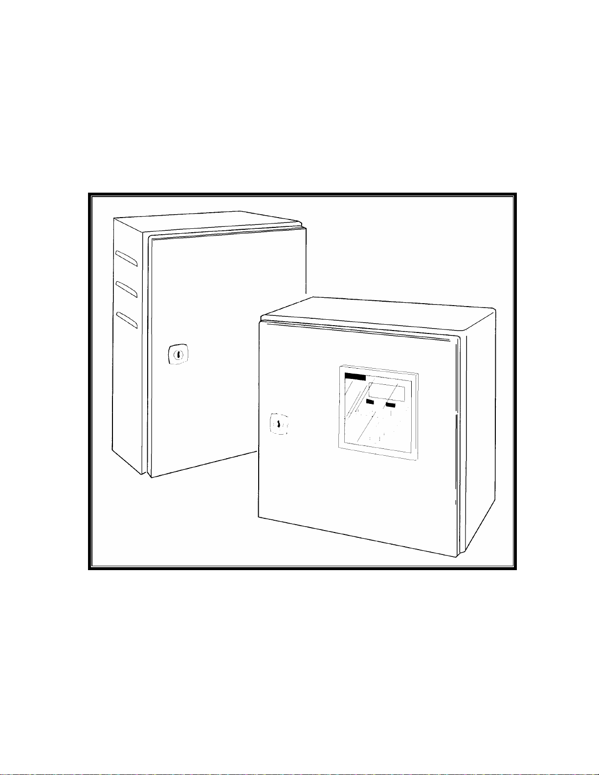
1.2 DESCRIPTION.............................................................................................................................. 1
1.2.1 SENSOR UNIT........................................................................................................................ 1
1.2.2 TRANSMITTER UNIT ............................................................................................................ 1
2INSTALLATION ................................................................................................................................. 3
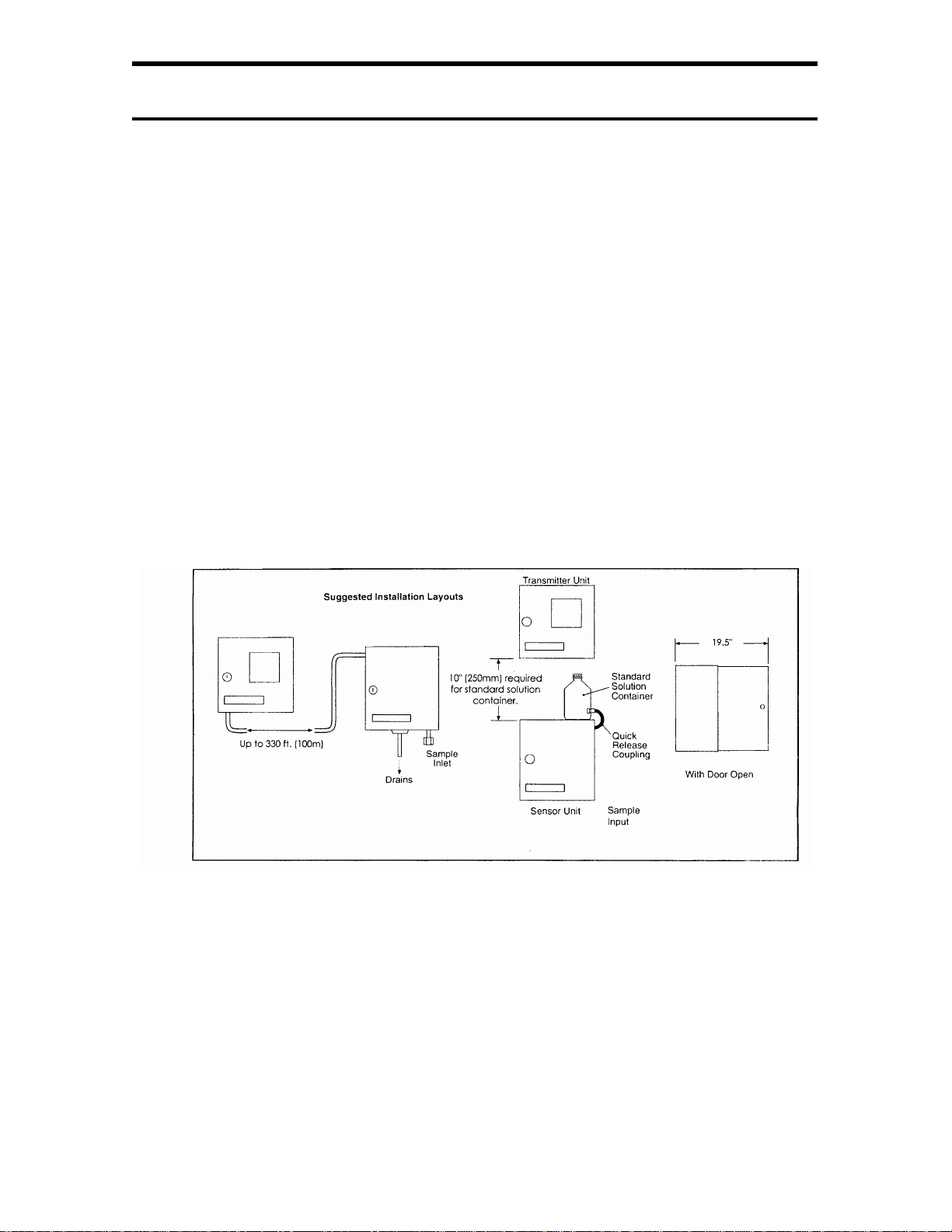
2.1 MOUNTING OF UNIT.................................................................................................................. 3
2.1.1 LOCATION AND LAYOUT.................................................................................................... 3
2.1.2 TRANSMITTER UNITS .......................................................................................................... 4
2.2 SAMPLE REQUIREMENTS......................................................................................................... 6
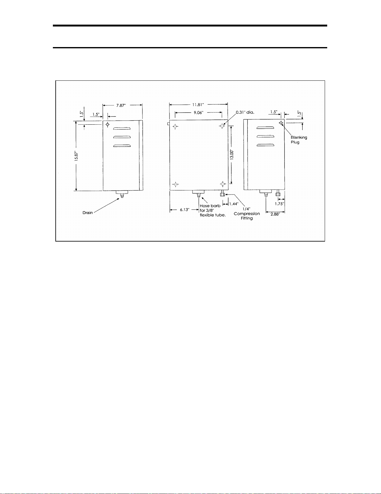
2.3 EXTERNAL PIPING CONNECTIONS......................................................................................... 6
2.3.1 INLET..................................................................................................................................... 6
2.3.2 DRAIN .................................................................................................................................... 6
2.4 ELECTRICAL CONNECTIONS................................................................................................... 7
2.5 SENSOR UNIT .............................................................................................................................. 7
2.5.1 TRANSMITTER UNIT ............................................................................................................ 7
2.5.2 WIRING OF BOARDS................................................................................................................ 8
Chassis.................................................................................................................................................. 10
2.6 REMOTE EQUIPMENT.............................................................................................................. 10
2.6.1
RECORDERS........................................................................................................................ 10
2.6.2
RANGE INDICATION.......................................................................................................... 10
3START UP .......................................................................................................................................... 12
4PRINCIPLE OF OPERATIONS...................................................................................................... 14
4.1 SENSOR UNIT ............................................................................................................................ 14
4.1.1 A flow schematic is shown in Fig. 4.1................................................................................... 14
4.2 QA/QC JUNCTION BOX SWITCH............................................................................................ 15
4.2.1 Normal Calibration .............................................................................................................. 15
4.2.2 Process Calibration.............................................................................................................. 15
4.2.3 QA/QC.................................................................................................................................. 15
4.3 TRANSMITTER UNIT................................................................................................................ 16
4.3.1 ELECTRONICS CHASSIS.................................................................................................... 16
4.3.2 CIRCUIT BOARD FUNCTION............................................................................................ 16
4.3.3 FRONT PANEL CONTROLS ............................................................................................... 17
4.3-4 ALARMS..................................................................................................................................... 20
4.4 ANALOG OUTPUTS................................................................................................................... 20
5CALIBRATION PROCEDURE....................................................................................................... 22
5.1 SINGLE POINT CALIBRATION USING STANDARD SOLUTION....................................... 22
5.2 CALIBRATION USING PROCESS SAMPLE AS ASTANDARD SOLUTION....................... 23
6MAINTENANCE ............................................................................................................................... 24
6.1 CHEMICAL SOLUTIONS .......................................................................................................... 24
6.1-1 BUFFER SOLUTION........................................................................................................... 24
6.1.1 Concentrated ammonia solution - 2 liters ............................................................................ 24
6.1-2 STANDARD SOLUTIONS........................................................................................................... 24
6.1-3 NITRIC ACID CLEANING SOLUTION............................................................................... 26
Note: Waltron L.L.C. offers Nitric Acid in a 2 ounce size part number H1234-556 ........................... 26
6.1-4 HYDRAZINE SENSOR RECHARGE GEL................................................................................. 26
6.2 SCHEDULED SERVICING ........................................................................................................ 26
i

TABLE OF CONTENT
9
6.2-1 BI- WEEKLY......................................................................................................................... 26
6.2-2 BI-MONTHLY....................................................................................................................... 27
6.2-3 QUARTERLY........................................................................................................................ 27
6.2-4 REFURBISHING THE SENSOR.......................................................................................... 27
6.3 SHUT DOWN PROCEDURE...................................................................................................... 28
6.3.1 STORAGE OF THE SENSOR..................................................................................................... 29
6.4 UNSCHEDULED SERVICING................................................................................................... 29
6.4.1 Display shows “CAL”:......................................................................................................... 29
6.4.2 Display flashes (reading) - “out”:........................................................................................ 30
6.4.3 Display shows “CF”:........................................................................................................... 30
6.4.4 Display flashes “reading” continuously............................................................................... 30
6.4.5 Display shows “Hot”: .......................................................................................................... 30
6.4.6 CALIBRATION FAIL ALARM.............................................................................................. 30
6.4.7 MALFUNCTIONS OF THE MONITOR............................................................................... 31
REPLACEMENT OF PLASTIC TUBING............................................................................................. 31
7SPRARE PARTS................................................................................................................................33
8SPECIFICATIONS............................................................................................................................ 34
8.1 INSTALLATION INFORMATION ....................................................................................................... 34
9OPERATOR’S NOTES ..................................................................................................................... 36
10 OUR COMMITMENT TO OUR CUSTOMERS........................................................................ 37
11 OBSERVING SAFETY............................................................................................................. 38
12 WARRANTY AGREEMENT....................................................................................................... 39
13 CHECK LIST OF MATERIALS.................................................................................................. 41
ii

1INTRODUCTION 9070
1INTRODUCTION
1.1 GENERAL
The µAI-9070 Hydrazine Analyzer is a continuous on-line monitor for direct
measurement of Hydrazine in boiler feedwater. The 9070 features low
maintenance, semi-automatic process or standard calibration; and high
accuracy, auto ranging and external (“grab”) sample analysis.
1.2 DESCRIPTION
1.2.1 SENSOR UNIT
The sensor unit is in a metal case, which also houses the liquid handling
equipment. Pipework carrying the sample is mounted on a panel, and bolted
to the back of the unit with four M6 bolts.
Mounted on the sensor unit door are the Buffer container and the junction box.
The junction box for the electrode’s connection is also mounted on the door.
A user-controlled switch in the junction box allows for either calibration on a
process sample, or a quality analysis/ quality control (QA/QC) test.
The liquid handling section contains a machined PVC head chamber. As
sample flows to the vapor entrainment “T,” the head chamber controls its rate
and pressure. (Pretreat the sample with an alkaline vapor to achieve the
correct pH value.)
The sample is then collected in a standpipe that forces sample flow through
the Hydrazine Sensor.
Use a standard solution of a known value under the control of the transmitter
unit to calibrate the sample.
The drain cup collects used sample and overflow, allowing for a single drain
connection.
1.2.2 TRANSMITTER UNIT
The transmitter unit is in a metal case similar to the construction of the sensor
unit’s, with a chassis unit supporting circuit boards and other electrical sub-
assemblies.
Microprocessor electronics control the functions of the transmitter. The three
main functions of the Hydrazine Analyzer are:
1

1INTRODUCTION 9070
9To interpret and to display a reading of hydrazine received from the
sensor unit,
9To control the calibration sequence,
9To provide various outputs to the remote equipment.
Displays are three-digit, seven-segment, light emitting diodes (l.e.d.), which
show the level of hydrazine and operational information as well. The operator
can see when the instrument is in the calibration mode, and when the
calibration has not been successful.
On the left-hand side of the transmitter unit are six access holes. These holes
are sized to accept cable glands for the interconnect cable, alarm signals,
current outputs and an alternating current (a/c.) power cable
2

2INSTALLATION 9070
2INSTALLATION
2.1 MOUNTING OF UNIT
2.1.1 LOCATION AND LAYOUT
Mount the sensor and transmitter units in a clean, vibration-free area, avoiding
direct radiant heat, sunlight and drafts. Avoid areas containing chlorinating
equipment.
Mount the sensor unit no more than 33 feet (10 meters) from its associated
sample coolers.
Mount the sensor unit on the wall using four 5/16” or ¼” bolts on 9.06” by
13.00” centers.
Refer to Figure 2.1 for the correct positioning of transmitter and sensor units.
FIGURE 2.1 MOUNTING ARRANGEMENTS
3

2INSTALLATION 9070
FIGURE 2.2 SENSOR UNIT DIMENSIONS AND INSTALLATION
2.1.2 TRANSMITTER UNITS
Wall mount using four 5/16” or ¼” bolts on 9.06” by 9.06” centers. Sufficient
access space, as detailed previously, must be left for making cable
connections to the transmitters and for the mounting of standard solution
containers.
4

2INSTALLATION 9070
FIGURE 2.3 TRANSMITTER UNIT DIMENSIONS AND INSTALLATION
For access and fitting of the transmitter unit, proceed as follows:
9Unlock the door and open fully.
9To release the face panel, use a small coin or similar tool to turn
the four plastic fasteners ¼ turn in either direction.
9Remove the chassis.
9Secure the transmitter case to the wall by four 5/16” or ¼” bolts.
Note. Before fitting the chassis unit and connecting it to the main
power supply, check that the voltage selector is set to the correct value.
Refer to Section 3 for procedures required before start-up.
Caution. When replacing the connection terminal blocks, make sure
that the blocks are aligned correctly to cover all of the associated
connecting pins.
5

2INSTALLATION 9070
9With the transmitter case secured to a wall or panel, open the
chassis to the case and wire the main power connection. Fit the
connection blocks onto the circuit boards.
9Fit the chassis unit, secure it with the captive screws and replace
any ground (earth) bonding leads.
9Position the face panel and secure it with the four plastic fasteners.
2.2 SAMPLE REQUIREMENTS
[Warning: Do not exceed the maximum pressures and temperatures
specified. If you use pressure-reducing equipment, install a pressure relief
valve between your equipment and the sample inlet to the monitor for safety
purposes.
Bring the sample to the temperature and pressure suitable for measurement,
using sample coolers and pressure-reducing equipment (see Section 8)
2.3 EXTERNAL PIPING CONNECTIONS
2.3.1 INLET
The sample should be connected to the sensor unit using ¼” o.d. tubing of
stainless steel or rigid plastic. Connect this to the sample inlet coupling on the
right hand side of the case’s bottom piece.
The inlet tube should be of sufficient wall thickness to withstand the highest
sample pressure, and pipe lengths should be kept short.
Where particulate matter is present (e.g. magnetite in boiler samples), fit a 60-
micron sample filter to the sample line.
A shut-off valve (not supplied with the monitor) is necessary in the sample
unit.
2.3.2 DRAIN
The drain from the cup at the bottom of the sensor unit case consists of a hose
barb suitable for 3/8” bore plastic or rubber tubing. Alkaline
effluent from the monitor and overflowing sample drains through this single
connection.
6

2INSTALLATION 9070
2.4 ELECTRICAL CONNECTIONS
[WARNING:
Although some instruments have internal fuse protection, you must use a suitably
rated external protection device, such as a fuse or miniature circuit breaker (MCB).
Switch off the power supply and any high-voltage operated control circuits before
making any connections.
The equipment operates on alternating current electricity. Always take suitable safety precautions to
avoid the possibilities of an electric shock.
2.5 SENSOR UNIT
The prefabricated, eight-conductor cable connecting the sensor unit to the
transmitter unit arrives in place from our factory. We’ve provided this
service to assist you to avoid opening the junction box, which could admit
moisture.
You may mount the transmitter either next to the sensor unit or up to 330 feet
(100 meters) away. Also allow sufficient space on the transmitter unit’s left-
hand side. The access plate and holes on the left side allow room for the
connection of cables to the unit.
Extend the cable by placing a junction box adjacent to the sensor unit, and by
using the required length of 8-conductor cable. You can specify the length of
interconnect cable you’ll need at the time of order.
2.5.1 TRANSMITTER UNIT
9Remove the four screws securing the access plate to the left-hand side
of the transmitter case. Fit suitable cable glands through the 7/8”
diameter holes. Insert the cables necessary for the power supply,
output signals, alarms and the remote function, if used.
9Open the transmitter’s door and remove the face panel.
7

2INSTALLATION 9070
9Make sure the interconnect cable from the sensor unit is long enough
to reach the transmitter easily. The cable should terminate on terminal
block TB3 on the analog board.
9Push the end of the cable through a gland in the left-hand side of the
transmitter case.
9Noting that the shield drain wire terminates at Pin 10 of TB2 on the
analog board, attach the remainder of the cable end to the terminal
block TB3, following the wiring diagram shown in Fig. 2.4. You may
pull the terminal block away from the pins on the board if required
FIGURE 2.4 WIRING THE INTERCONNECT CABLE TO TRANSMITTER
Caution: The terminal block for the sensor unit connection has eight
terminals, yet there are 12 pins on the board. Make sure that you choose the
correct eight pins for the connection: These are marked on the PCB, with a
separate silk-screened “box”.
2.5.2 WIRING OF BOARDS
Pass any remaining cables through the appropriate glands. Note that Pin 1 of
each block is nearest the top of the case. Prepare the cable ends and attach
them to the terminal blocks as follows:
Digital Board (nearest front panel): No Terminations
8

2INSTALLATION 9070
Analog Board TB1
Analog Board TB2
Analog Board TB3
9

2INSTALLATION 9070
PSU Board TB3
Chassis
A voltage selector is next to the power supply terminal block. Set this voltage
selector to the correct voltage before connecting the instrument to the power
supply. Make sure that all of the gland nuts are tightened.
[Warning: Connecting the power supply ground (earth) ensures the safety
of your personnel, the reduction of the effects of Radio Frequency
Interference (RFI), and the correct operation of the power supply interference
filter.
2.6 REMOTE EQUIPMENT
2.6.1 RECORDERS
The choice of two different isolated recorder output signals enables you to use the
instrument with a wide variety of recording and data processing equipment. The load
requirements are shown in Section 8, and the positions of the circuit board switches are
given in Section 4.3.
2.6.2 RANGE INDICATION
The remote range indication relays (TB1 connections) can be used in several different
arrangements to suit the requirements of the installation. The relays can, for example, be
wired directly into a PLC or data logger, but if you use a recorder, you’ll need a method
of indicating the set range. A two-pen recorder is necessary: Pen 1, to indicate the
hydrazine concentration; and Pen 2, to record the instrument range.
10

2INSTALLATION 9070
Use a resistor network to achieve the suitable range recorder input. Connect
the resistors as shown in the two examples in Fig. 2.5. (Our example consists
of four ¼-watt resistors). A suitable resistor network kit is listed in Section 7.
Your external equipment should be set up using the manufacturers’ instructions.
FIGURE 2.5 RESISTOR NETWOK FOR ‘AUTO’ REMOTE RANGE INDICATION
RECORDERS
11

3STARTUP 9070
3START UP
9Open the transmitter unit’s door and remove the face panel. Verify that the switch
next to the battery is set to “ON”. Replace the face panel and secure it with the
four plastic fasteners.
9Power up the monitor at the external source and set the Range Switch to
“AUTO”.
9Unpack the hydrazine electrode and carefully remove the hydrazine gel syringe
and plunger.
9Verify that the clear outer jacket of the sensor is firmly in place. Locate the gel
filling hole near the bottom of the jacket and the air vent hole near the top of the
outer jacket.
9Use either a knife or a pair of scissors to remove the plugged tip of the gel-filled
syringe. Be careful not to remove too much of the tip, as the syringe will no
longer fit into the gel filling hole in the sensor outer jacket. Verify that the gel is
an even, dark color. Discard gel that is brown, green, gray or dry.
9Place the syringe tip into the gel-filling hole. Make sure the air vent hole is
unobstructed. Depress the plunger of the syringe to force gel into the round space
between the sensor and outer jackets. Continue pressing until the entire jacket is
filled with gel and gel starts to force out through the air vent hole. Remove the
syringe and discard any remaining gel.
9Cover both filling and vent holes with Teflon pipe tape. Wrap each hole with
three to four turns of tape.
9Snap the assembled sensor into the two mounting clips on the sample panel. The
hose barb at the bottom of the sensor should point toward the lower left corner of
the sample panel.
9Connect the “J” bend tube to the hose barb at the bottom of the sensor, but make
sure that the sensor does not push out of the outer jacket.
9Fill the Buffer solution container with ammonium hydroxide—see Section 6.
9Open the shut-off valve upstream of the sensor unit and adjust the valve until the
sample is overflowing from the constant head unit. See Section 8 for the
maximum and minimum flow rates.
9Allow at least one hour before going on to the next step.
12

3STARTUP 9070
9Set up the transmitter as described in Section 4.2.
9Carry out a calibration as detailed in Section 5.
9The monitor is now in operation. The lamp adjacent to the number display
indicates the hydrazine level (units of measurement in ppb) or the sample
temperature (in degrees Celsius).
9If required, turn the range switch to one of the “Non-Auto” ranges.
9Press the “ALARM 1” button and use the “UP/DOWN” buttons to set the desired
value. Repeat for “ALARM 2”.
13

4PRINCIPLEOFOPERATIONS 9070
4PRINCIPLE OF OPERATIONS
4.1 SENSOR UNIT
4.1.1 A flow schematic is shown in Fig. 4.1.
The sample enters the compression fitting at the bottom of the case and passes
through one half of a heat exchanger. This heat exchanger, used during the
calibration sequence to bring the standard solution temperature close to the
temperature of the sample solution, minimizes calibration time.
FIGURE 4.1 SCHEMATIC FLOW DIAGRAM
From the heat exchanger, the sample passes through a solenoid valve to the
constant head unit. Here, the head unit stabilizes the effect of changes in
sample pressure and flow rate. When the monitor loses sample, a small tube
overflowing into the constant head on one side ensures a self-start. This tube
also permits the monitor to function over a wide range of sample flow rates.
The sample is then delivered to the Entrainment “T” and stainless steel
entrainment tube. An alkaline vapor Buffer is added to the sample to raise its
pH value before flowing through the hydrazine sensor. The sample leaves the
sensor and drips into the drain at the bottom of the case.
The signal from the electrode pair travels to a junction box and hence, to the
transmitter unit via the interconnection cable.
14

4PRINCIPLEOFOPERATIONS 9070
A temperature sensor, fitted into the hydrazine sensor, detects the sample’s
temperature. The sensor, connected to the transmitter unit, compensates for
changes in output from the electrode pair over a range of 41°F to 131°F (5°C
to 55°C).
The microprocessor controls the monitor’s calibration. After you connect the
calibration tube to the standard solution container, press the “CAL” button on
the transmitter unit. This action energizes the solenoid valve on the liquid
handling panel to change over from sample to standard solution. The standard
solution first passes through the second half of the heat exchanger. Then the
constant head unit and the vapor entrainment tube present the solution to the
hydrazine sensor.
The solenoid valve is closed to the sample during a calibration sequence, but
under sample pressure, the pressure relief valve will open. The valve will
allow the sample to pass through the heat exchanger, thus bringing the
standard solution to a similar value to the sample solution.
4.2 QA/QC JUNCTION BOX SWITCH
The junction box in the sample cabinet offers the ability to calibrate the
analyzer on the sample process or to measure a QA/QC standard for system
accuracy verification.
4.2.1 Normal Calibration
When an operator places the switch in this position, it allows normal
calibration of the analyzer with a known standard solution.
4.2.2 Process Calibration
When an operator places the switch in this position, the solenoid valve is
inhibited, allowing the system to be calibrated on a known value for the
sample process water. Note that the minimum setting for the standard value is
20 ppb.
4.2.3 QA/QC
When the operator places the switch in this position, the system will draw
sample from the external standard solution bottle without having to start a
calibration. You can check and verify the system against a known standard
solution.
15

4PRINCIPLEOFOPERATIONS 9070
4.3 TRANSMITTER UNIT
4.3.1 ELECTRONICS CHASSIS
The chassis contains three circuit boards:
9Digital Board - Behind the faceplate, containing the central
processor unit, front panel controls and the display.
9Analog Board - Middle board, containing the analog input and
current output circuitry.
9PSU Board - Rear board, containing the power supply and
output relays.
4.3.2 CIRCUIT BOARD FUNCTION
The microprocessor senses a series of eight “ON/OFF” switches in a dual-in-
line package, and provides controlling functions for the alarms, output current
and calibration - see Table 4.2.
FIGURE 4.2 CIRCUIT BOARD FUNCTION SWITCH
16

4PRINCIPLEOFOPERATIONS 9070
FIGURE 4.3 LOCATION OF ITEMS ON DIGITAL BOARD
4.3.3 FRONT PANEL CONTROLS
The controls, mounted on the front circuit board in the chassis, protrude through
holes in the faceplate. Four plastic fasteners secure the chassis to the faceplate.
A three-digit, red, l.e.d. display shows the hydrazine level in ppm or ppb as
indicated by a lamp in the display. The controls have the following functions:
17
Table of contents
Other Waltron Measuring Instrument manuals

Waltron
Waltron 3049 User manual

Waltron
Waltron 9091C User manual

Waltron
Waltron 9096 User manual

Waltron
Waltron 9033X User manual

Waltron
Waltron 3046 User manual

Waltron
Waltron 3048 User manual

Waltron
Waltron 2410 User manual

Waltron
Waltron 9031CX User manual

Waltron
Waltron 9092 User manual

Waltron
Waltron Aqualert 6051 User manual
Popular Measuring Instrument manuals by other brands

Carlson
Carlson Void Scanner user manual

Kobold
Kobold HEINRICH DWF-S Installation and operating manual

Lumel
Lumel NA5 Series user guide

CTC Union
CTC Union MMX-MOD3 Series installation manual

DMP Electronics
DMP Electronics 1117 installation guide

Hanna Instruments
Hanna Instruments HI 99121 instruction manual