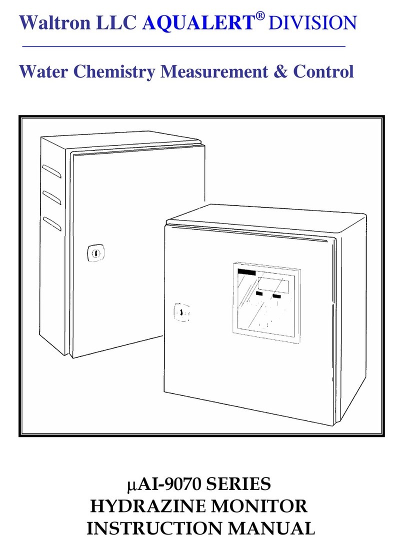
Waltron 9072 User manual

101-054-A.1
EXPERTS IN WATER CHEMISTRY SINCE 1903
9072 Hydrazine Analyzer
User Manual

1
Waltron User Manual 101-054-A.1
9072 Hydrazine Analyzer
WALTRON CUSTOMER COMMITMENT
This instruction manual is a technical guide to aid the customer in the set-up, operation,
and maintenance of their new Waltron measuring system. Waltron provides continuous
product improvement and reserves the right to make any modifications to the information
contained herein without notice.
Copyright © Waltron Bull & Roberts, LLC, 2019
All Rights Reserved
Technical questions concerning this product should be addressed to:
Waltron Technical Service Department
Flemington, New Jersey
Phone: (908)-534-5100
Fax: (908)-534-5546
www.waltron.net
Please be ready to provide the following information:
Date analyzer was purchased
Analyzer model and serial number
Recent maintenance history
Calibration slope values and detailed description of problem
Waltron’s technical expertise and extensive experience provides personalized solutions to
the water quality industry. It is Waltron’s commitment to provide the customer with
timely and accurate technical service and support.
Waltron fully expects the customer to be satisfied with the quality, performance, and cost
of this product.
If there are any questions or concerns regarding this product, please feel free to contact
Waltron at (908)-534-5100.
Thank you for choosing Waltron!
Please note the Waltron mailing and shipping address:
Waltron Bull & Roberts, LLC
25 Minneakoning Road, Suite 101
Flemington, NJ 08822

2
Waltron User Manual 101-054-A.1
9072 Hydrazine Analyzer
SAFETY
Please observe proper safety and handling precautions when installing, operating,
maintaining, and servicing this product. The following should be noted and adhered to:
Read and understand manual before working with analyzer.
Pay special attention to warning labels on enclosures, containers, packages and
chemicals.
Only qualified personnel should be involved in the installation, operation, and
servicing of the analyzer.
Follow safety precautions when operating analyzer in conditions of high pressure
and/or temperature.
Keep analyzer chemicals away from heat and extreme temperatures. Reagent
powders must be kept dry.
Follow all regulations and warning labels when disposing of chemicals. Do not
mix chemicals.
To obtain analyzer safety information or Safety Data Sheets (SDS), please contact
Waltron or logon to www.waltron.net.

3
Waltron User Manual 101-054-A.1
9072 Hydrazine Analyzer
WARRANTY AGREEMENT
If, within one year from the date of shipment, the customer experiences any equipment
defects or is not satisfied with the analyzer manufacturing, Waltron will repair, or at its
option, replace any defective part(s) free of charge. This warranty requires that the
defective part(s) be returned to Waltron with shipping charges prepaid.
At Waltron discretion, a Technical Service Specialist may be sent out to repair or replace
the defective part(s) on location. Traveling time and expenses of the Technical Service
Specialist is at the customer’s expense.
Equipment sent to Waltron must be appropriately packaged and the following
information must be provided prior to returning to Waltron:
The Return Authorization (RA) number assigned to the customer by the Waltron
Technical Service Department
Customer name, address and department
Name and telephone number of the individual responsible for returning items for
repair
Brief problem description
Ship to Waltron service center:
Waltron Bull & Roberts, LLC
25 Minneakoning Road, Suite 101
Flemington, NJ 08822
The Waltron Warranty Agreement:
Covers expendable sensors for one month after shipment and reusable electrodes
for six months after shipment.
Does not apply to damages occurred during shipping.
Warranty will be nullified if goods have been used for purposes other than those
for which they are intended or if any seal has been removed, broken or tampered
with or if the Waltron trademark or serial number has be removed, defaced, or
altered.
Does not cover expendable supply items such as reagents, tubing and
electrolytes.
Does not cover misuse or mistreatment by the user.
Does not cover previous repair or alteration by unauthorized individuals.
Waltron does not assume responsibility for contingent liability through alleged failure or
failures of products or product accessories.

4
Waltron User Manual 101-054-A.1
9072 Hydrazine Analyzer
CHECKLIST OF MATERIALS
In order to ensure customer satisfaction, Waltron does its best to provide
adequate and timely packaging and shipping services. Please perform the
following after receiving a shipment:
Inspect all shipping containers upon receipt and record any visible damage. If
there are any outward signs of damage, please retain all containers and packages
for inspection by carrier. Please retain all packing material so that it can be used
for future moving and shipping needs.
Check all items received against those on the packing list. Chemicals are usually
shipped in a separate package and will be itemized accordingly.
Verify that the number of packages received agrees with the packing list and
shipping papers.
Notify both Waltron and the carrier if any problems occur.
Important Notice:
All analyzers are inspected and tested prior to shipment.
In normal use, the unit should require only minor maintenance and should
operate correctly and without fault over a long period of time.
Please note that if electronic components need to be replaced, it may be
necessary to adjust and/or calibrate the analyzer.
Failure to carry out correct maintenance procedures may result in inaccurate
analyzer readings.

5
Waltron User Manual 101-054-A.1
9072 Hydrazine Analyzer
Table of Contents
1 INTRODUCTION..................................................................................................... 6
1.1 AREAS OF APPLICATION.............................................................................. 6
1.2 DESCRIPTION OF DEVICE............................................................................. 7
1.3 THE MEASURING SYSTEM........................................................................... 8
1.4 BLOCK DIAGRAM OF SENSOR SYSTEM.................................................... 9
2 INSTALLATION.................................................................................................... 10
2.1 DELIVERED PARTS....................................................................................... 10
2.2 ACCESSORIES................................................................................................ 14
2.3 TERMINAL SCHEMATIC.............................................................................. 14
2.4 TECHNICAL DATA........................................................................................ 15
3 OPERATING PROCEDURES.............................................................................. 16
3.1 PRINCIPLES OF MEASREMENT ................................................................. 16
4 START-UP............................................................................................................... 16
4.1 MENU STRUCTURE ...................................................................................... 16
4.2 PREPARING TO MEASURE.......................................................................... 18
4.3 CHOICE OF OPERATING PARAMETERS .................................................. 18
5 MEASURING MODE............................................................................................ 20
5.1 OPERATING CONDITIONS .......................................................................... 20
5.2 ANALYZER CALIBRATION......................................................................... 20
6 MAINTENANCE.................................................................................................... 22
6.1 CLEANING OF ELECTRODES ..................................................................... 22
6.2 CLEANING OF CELLS................................................................................... 22
7 TROUBLESHOOTING......................................................................................... 23
8 SPARE PARTS AND ACCESSORIES ................................................................ 24

6
Waltron User Manual 101-054-A.1
9072 Hydrazine Analyzer
INTRODUCTION
1INTRODUCTION
1.1 AREAS OF APPLICATION
The Waltron 9072 Hydrazine Analyzer is used for the automatic, continuous
measurement and control of hydrazine concentration in aqueous solutions. Examples of
the applications of the unit include the determination of residual hydrazine concentration
in boiler feedwater in power plants, the monitoring of hydrazine concentration in the
primary loop of a nuclear power plant, the monitoring of hydrazine concentration during,
or the indication of the hydrazine concentration during the reduction of oxygen in water
treatment plants etc.
Hydrazine is used as a reducing agent and oxygen scavenger in fossil fueled boiler
systems, generally in AVT (All Volatile Treatment) process streams. The hydrazine
creates a reducing environment to protect copper containing metallurgy and serves to
reduce the dissolved oxygen concentrations to protect iron containing metallurgy.
Hydrazine concentration needs to be continuously monitored to provide feedback to the
chemical injection systems and to ensure that the correct concentrations are present in the
system.
In the primary loop of a nuclear power plant the hydrazine should reduce or mitigate the
oxygen which is produced by radiolysis. As a result the electro-chemical corrosion
potential (ECP) of the tube material is reduced. In nuclear power plant applications,
hydrazine is added to scavenge oxygen or recombine with the oxygen that is produce by
radiolysis. In the pressurized water reactor (PWR) primary loop, hydrazine is measured
in the range 25-50cc/kg. Hydrazine in boiling water reactors (BWR) feedwater and
reactor coolant is measured in ppm’s. Hydrazine in feedwater is typically 0-2ppm and
hydrazine in reactor coolant water will vary between 0.1-0.5ppm.
For boilers that operate with a pressure higher than 62 bar (900 psi), hydrazine is often dosed
to scavenge oxygen. Hydrazine (N2H4) reacts with oxygen as follows:
N2H4 + O2 => H2O + N2

7
Waltron User Manual 101-054-A.1
9072 Hydrazine Analyzer
INTRODUCTION
1.2 DESCRIPTION OF DEVICE
The Waltron 9072 Hydrazine Analyzer measures reliably and quickly the hydrazine
concentration in aqueous media from the trace areas (<10.0 µg/l) up to concentrations of
higher than 1000 µg/l under normal conditions.
The Waltron 9072 Hydrazine Analyzer can be divided into two primary function parts.
The first is the electronic component which consists of the display and input elements as
well as the measuring data collection and data processing elements.
The second is the analytical component which is composed of the inlet valve, filter
device and flow meter which serve the sample and probe preparation. The measuring cell
is joined with the temperature sensor and the reference cell with its reference electrode.
For the measurement of the hydrazine (N2H4), the sample flows through the components of
the device which relate to the sample and probe preparation and through the calibration cell
into the coaxial measurement cell (grooved measurement cell), passing by the gold
measuring electrode. If the measuring electrode has the characteristic potential for the
hydrazine oxidation in the boundary layer (interphase) between the electrode surface and
medium, the measurement reaction takes place.
Waltron 9072 Hydrazine Analyzer

8
Waltron User Manual 101-054-A.1
9072 Hydrazine Analyzer
INTRODUCTION
1.3 THE MEASURING SYSTEM

9
Waltron User Manual 101-054-A.1
9072 Hydrazine Analyzer
INTRODUCTION
1.4 BLOCK DIAGRAM OF SENSOR SYSTEM

10
Waltron User Manual 101-054-A.1
9072 Hydrazine Analyzer
INSTALLATION
2INSTALLATION
2.1 DELIVERED PARTS
Arrangement of the wall mounted instrument
M: measuring electrode
C: counter electrode
R: reference electrode
T: temperature sensor

11
Waltron User Manual 101-054-A.1
9072 Hydrazine Analyzer
INSTALLATION
TRANSMITTER MOUNTING

12
Waltron User Manual 101-054-A.1
9072 Hydrazine Analyzer
INSTALLATION
WET SECTION MOUNTING

13
Waltron User Manual 101-054-A.1
9072 Hydrazine Analyzer
INSTALLATION
2.2 ACCESSORIES
1. 100 ml KCl-solution
2. 1 kg granular marble
3. 1 test tube brush
4. 1 cleaning material
5. 1 software for digital measuring (option)
2.3 TERMINAL SCHEMATIC
Terminal Block Left:
L
N
PE
1
2
3
4
5
6
7
8
9
Line 100-230 V
50/60 Hz
Line 100-230 V
50/60 Hz
Ground (earth)
Limit alarm (off)
Limit alarm (on)
Limit alarm
(common)
Alarm on
Alarm off
Alarm (common)
Auto changing
range 2
Auto changing
range 1
Auto changing
(common)
Terminal Block Right:
1
2
3
4
5
6
7
8
9
10
11
12
13
14
15
16
17
18
0(4)..20 mA -
0(4)..20 mA +
Cal. electrode +
(A)
Cal. electrode -(K)
Flow (signal)
Flow
Flow +
Temp.sensor
(common)
Temp.sensor
(common)
Temp.sensor +
NC
Reference el. (R)
Counter el. (C)
Measure el. (M)
NC
TxD (RS 232)
GRD (RS 232)
RxD (RS 232)

14
Waltron User Manual 101-054-A.1
9072 Hydrazine Analyzer
INSTALLATION
2.4 TECHNICAL DATA
Measurement principle:.........
microprocessor based, potentiostatic three electrode system
Calibration:............................
build-in, single button operation
Auto-calibration:....................
option
Measuring range:
Measuring group I:................
0,0..........1000,0 µ g/l
range selectable between 20....1000 µg/l
Measuring group II:...............
0,00........10,00 mg/l
range selectable between 0.2....10 mg/l
Auto-changing-range:............
Built in
Analog output:.......................
0(4)............20 mA; shunt max. 500 Ohm
Digital output:........................
serial interface RS 232
Data logging:.........................
Ring time buffer 21,000 data points, time set 1 s to 5 min
Limit:.....................................
power relay
Alarming:...............................
power relay; Flow and Calibration
Measuring electrode:.............
gold
Counter electrode:.................
stainless steel 1.4571 (314)
Reference Electrode:.............
Ag/AgCl in saturated KCl-solution
Calibration electrode:.............
None
Response time t90:................
8 sec
Probe conductivity:................
≥ 3 µ S/cm; (if conductivity is less a salt cell is required)
Ambient temperature:............
0.....+55 °C
Sample temperature:.............
0.....+60 °C, automatic compensation
Sample pressure:.................
≤ 8 bar (116 psi)
Sample flow:........................
3 l/h ......20 l/h
Sample fittings:...................
tube fittings for tube ∅6 mm
Error limits:............................
< 1 % in range 1000,0 μg/l, or ±2% in range 100,0 μg/l
Protection class:.....................
IP 65
Color:.....................................
basic parts RAL 7035; front and rear parts RAL 7024
Voltage:..................................
100...240 VAC, 50/60 Hz
Power consumption:...............
10 VA

15
Waltron User Manual 101-054-A.1
9072 Hydrazine Analyzer
OPERATING PROCEDURES
3OPERATING PROCEDURES
3.1 PRINCIPLE OF MEASUREMENT
The 9072 Hydrazine Analyzer electrochemical hydrazine sensor functions in a
potentiostatic mode with an open three-electrode system. The measuring electrode is
made of solid titanium, coated with gold. The counter electrode is made of stainless steel
and the reference electrode is made of silver/silver-chloride. The use of open measuring
electrode means, that there is a direct contact between the sample and the measuring
electrode. A membrane is not required. For the measurement of dissolved hydrazine
(N2H4) the fluid medium flows into the coaxial measurement cell between the platinum
measuring electrode and counter electrode. If the measuring electrode has reached the
correct potential, hydrazine is oxidized in the interphase boundary layer. The
electrochemical reaction may represented qualitatively as:
N2H5OH + 4OH- N2 + H2O + 4e-
The characteristic potential for this reaction the potential at which hydrazine oxidation occur
in preference to other competing reactions is measured by holding the potential of the
measuring electrode steady with a potentiostatic and comparing its value with that of the
reference electrode. Under these conditions the rate of the electrochemical reaction is limited
by the rate of diffusion of hydrazine molecules to the electrode. As long as we remain within
this ‘diffusion-limiting-current’ area, the electrochemical cell delivers an electric current,
whose size depends linearly on the concentration of dissolved hydrazine. This current, which
is measured by the instrument’s electronic processing unit, is known as the diffusion-limiting
current,
Idiff: cN2 H4 = k • Idiff
This diffusion-limiting current depends mainly on the mass transport of the
electrochemically active components, and hence on the hydrodynamics in the measuring
cell. It therefore changes significantly with the temperature and flowrate through the
measuring cell. In practice the flowrate and temperature vary over wide ranges, but the
instrument corrects these changes by using empirical correlations.
A second important influence on the measurement is the condition of the electrodes. In
particular the adsorptive and oxidative state of the electrode surface layers. This is
independent of the flow conditions; it depends instead on the voltage between the
electrode and the electrolyte, and on the material of which the electrode is made
Appearing flow- and temperature effects of the measuring signal are recorded with the
aid of the installed flow meter and temperature sensor and are compensated, if necessary.

16
Waltron User Manual 101-054-A.1
9072 Hydrazine Analyzer
START-UP
4START-UP
4.1 MENU STRUCTURE
H2 100 μg/l
>
Please insert PIN
10.4 μg/l
0000
SET
9.1 l/h 22.2°C
Menu 01/11
Range
Range >
000.0 μg/l
SET
CalModus 3/1
ElyseCal
ElyseCal Countdown
ElyseCal >
Press > to start Elyse
6:00 min
Menu 02/11
CalModus 3/2
SubCal
CalModus >
SubCal >
000.0 μg/l
CalModus 3/3
AutoCal 1/3
AutoCal Date/Time
AutoCal >
Date/Time >
01.01.2000 12:00
SET
Menu 03/11
RangeModus 1/2
AutoCal 2/3
AutoCal Period 1/3
RangeModus >
ManRange
SET
Period >
daily
RangeModus 2/2
AutoCal Period 2/3
AutoRange
SET
weekly
Menu 04/11
I-Output
AutoCal Period 3/3
I-Output >
0..20 mA
SET
monthly
I-Output
AutoCal 3/3
AutoCal Control 1/2
4..20 mA
SET
Control >
deactivated
Menu 05/11
Limit
AutoCal Control 2/2
Limit >
000.0 μg/l
SET
activated
Menu 06/11
FlowCal
FlowCal Volume
FlowCal Volume
FlowCal >
Press > to start
60 sec
000.0 ml
SET
!!Caution!!
Parameter 1/2
Kd
Menu 07/11
You enter a site
with critical content
Kd >
1.123
Parameter
Press SET to enter
Parameter 2/2
K
K >
1.100
continued

17
Waltron User Manual 101-054-A.1
9072 Hydrazine Analyzer
START-UP
from previous
Menu 08/11
Logging 1/4
Logging Info
Logging >
Info >
Logging active
01.01.00 12:00
000011 entries
Logging Info
Logging stopped
01.01.00 12:00
No entries
Logging 2/4
Logging Interval 1/5
Interval >
10 sec
SET
Logging Interval 2/5
30 sec
SET
Logging Interval 3/5
1 min
SET
Logging Interval 4/5
2 min
SET
Logging Interval 5/5
5 min
SET
Logging 3/4
Logging Control
Control
Press > to stop logging
Logging Control
press > to reset
Press > to continue or
!!Caution!!
SET to restart logging
Old data are lost
Logging 4/4
LogDownload
Download >
Data acquisition spped
Menu 09/11
Date/Time
Date/Time >
01.01.2000 12:00
SET
Menu 10/11
Service 1/5
Service >
For service only
Menu 11/11
New PIN
Repeat PIN
Change PIN >
0000
SET
0000
SET

18
Waltron User Manual 101-054-A.1
9072 Hydrazine Analyzer
START-UP
4.2 PREPARING TO MEASURE
Before you start to measure you must perform the following procedures:
1. The electrical power supply has to be connected according to the local power
authority guidelines with the terminal box, with which the connectors to the
0(4)...20 mA analog output (see the circuit diagram on the cover plate) should be
combined.
2. The reference cell has to be filled with KCl solution. The reference cell must be
removed from the measuring cell by unscrewing the reference cell. Take out the
reference electrode and fill up the KCl solution to the level of about the beginning
of the external threading. Make sure that no air bubbles develop near the
diaphragm. Tap the cell gently if necessary. Remove any surplus of the KCl
solution and reinsert the reference electrode. Make sure that the installation of the
O-ring is correct.
3. If the sample has a conductivity of ≤3 μS/cm, the salt cell (option) must be filled
with granular marble (calcium carbonate CaCO3). To do this unscrew the cover
and pour in the granular marble carefully into the large cavity.
4. The probe tube is connected with tube fittings to the inlet valve. The outlet line is
placed at the measuring cell exit with a hose having a 5 mm inside diameter.
4.3 CHOICE OF OPERATING PARAMETERS
Before starting measurement, set your operating parameters. With the keys at the front
site you can move through the menu. To enter the menu, press key and insert your
code number (Pre setting: 0000; see page 17). With the keys and you move one
step in the vertical direction up or down and also increase or decrease numbers. With the
key SET you confirm chosen parameters, with the key ESC you jump back one step in
the horizontal direction with no effect.
If a > sign is displayed, you can go with the key right ahead in a sub-level.
The menu consists of eleven levels. You find your present position on the right top of the
display.
1st Menu level Range > shows range settings. The value is corresponding to the
maximum analog output current of 20 mA. Press key and make your choice by setting
digit for digit and press the adjacent key SET. Your range is now selected and the
indication jumps one step back in the Menu.
2nd Menu level shows the calibration settings named CalModus >. Press key to jump to
the sub-level CalModus > which consists of three sub-levels called: ElyseCal >, SubCal
> and AutoCal >. (option only). With the key you can go ahead. With the key you
will release the electrolytic calibration if you start from position ElyseCal >. From

19
Waltron User Manual 101-054-A.1
9072 Hydrazine Analyzer
START-UP
SubCal > you are setting the present hydrazine concentration digit for digit, finally push
key SET.
3rd Menu level Range Modus > gives you the choice between ManRange (range which is
setting in 1st level only) and AutoRange (automatic changing range which has double
value of ManRange >)(Option only).
4th Menu level I-Output > sets the analog output current 0(4)...20 mA.
5th Menu level Limit > allows limit settings. There exists a switch hysteresis of 10% of
the chosen limit.
6th Menu level FlowCal > enables flow meter calibration (see Section 7).
7th Menu level Parameter > shows operation parameters Kd (flow) and k (calibration).
Attention: Only reading parameter.
8th Menu level Logging > is the data logging function (Option only).
9th Menu level Date/Time > allows date settings.
10th Menu level Service > is for service only.
11th Menu level ChangePIN > gives you the possibility to change your PIN number.
Attention: lost PIN numbers can only activated by the manufacturer.
Table of contents
Other Waltron Measuring Instrument manuals
Waltron
Waltron 9033X User manual

Waltron
Waltron Aqualert 6051 User manual

Waltron
Waltron AQUALERT Aqualyzer 3051 User manual

Waltron
Waltron 9091C User manual

Waltron
Waltron 9032X User manual

Waltron
Waltron 3048 User manual

Waltron
Waltron 3046 User manual

Waltron
Waltron Aqualert 6051 User manual

Waltron
Waltron 2410 User manual

Waltron
Waltron 3049 User manual
Popular Measuring Instrument manuals by other brands

halstrup-walcher
halstrup-walcher PU Original instruction manual

Knick
Knick 830 R manual

SIGLENT
SIGLENT SHA850A quick guide

Beta LaserMike
Beta LaserMike LaserSpeed LS9000 Operator's guide

EUTECH INSTRUMENTS
EUTECH INSTRUMENTS CON 700 - REV 2 instruction manual

Coulometrix
Coulometrix Metiri COUMET60100SC user manual