WAM WAMFLO FOOD FN200X User guide

2
ROUND DUST COLLECTORS
FOR POTENTIALLY EXPLOSIVE
ATMOSPHERES AREAS
WAMFLO®
FOOD
FN200X
EN
ASSEMBLY AND
MAIN INSTRUCTIONS
FOR USE AND
MAINTENANCE
fax
e-mail
internet
+ 39 / 0535 / 618111
+ 39 / 0535 / 618226
www.wamgroup.com
WAMGROUP S.p.A.
Via Cavour, 338
I-41030 Ponte Motta
Cavezzo (MO) - ITALY
Manual No. FIL.WAMFLO_FN200.EX.M.A7.0522.EN
Issue: A7 Latest update: May 2022 Code:
063002448
Division: FIL
ORIGINAL INSTRUCTIONS IN ENGLISH

All the products described in this catalogue are manufactured according to WAMGROUP S.p.A. Quality System procedures.
The Company’s Quality System, certied in July 1994 according to International Standards UNI EN ISO 9002 and extended to
the latest release of UNI EN ISO 9001, ensures that the entire production process, starting from the processing of the order to the
technical service after delivery, is carried out in a controlled manner that guarantees the quality standard of the product.
This publication cancels and replaces any previous edition and revision.
We reserve the right to implement modications without notice.
This catalogue cannot be reproduced, even partially, without prior written consent by the Manufacturer.

INDEX
WAMFLO® FN200X
2
FIL.WAMFLO_FN200.EX.M.A7.0522.EN Issue: A7
05.22
III
1.0 GENERAL INFORMATION ...................................................................................................................... 1
1.1 Scope of the Manual ......................................................................................................................... 1
1.2 Symbols ............................................................................................................................................ 2
1.3 Glossary and terminology ................................................................................................................. 4
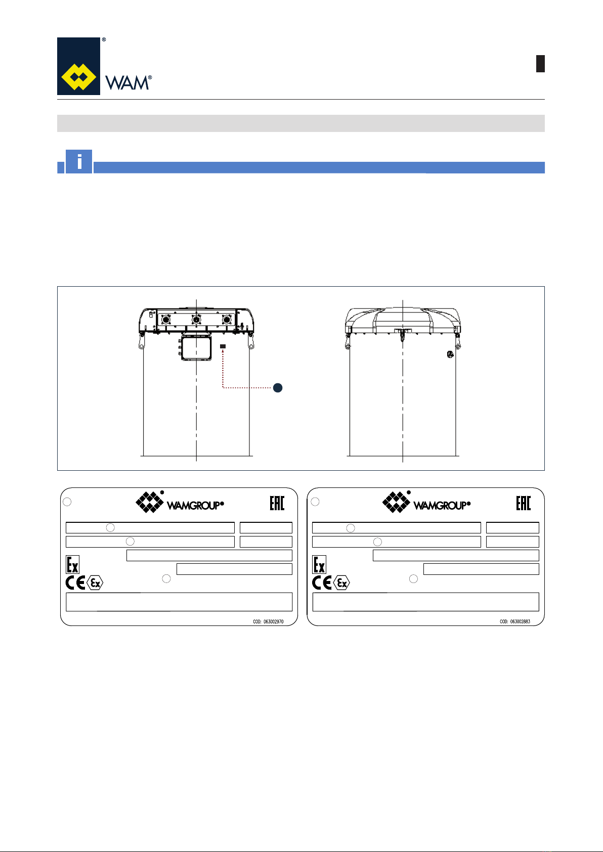
1.4 Manufacturer’s data and identication of equipment......................................................................... 5
1.5 Request for assistance...................................................................................................................... 6
1.6 Warranty............................................................................................................................................ 6
1.7 Exclusion of responsibility ................................................................................................................. 6
2.0 INFORMATION REGARDING SAFETY................................................................................................... 7
2.1 General safety prescriptions ............................................................................................................. 7
2.2 Safety prescriptions for transport and handling................................................................................. 7
2.3 Safety prescriptions for installation ................................................................................................... 8
2.4 Safety prescriptions for use and operation........................................................................................ 8
2.5 Safety prescriptions for maintenance and replacement of components ........................................... 8
2.6 Safety recommendations on biological risks ..................................................................................... 9
3.0 TECHNICAL INFORMATION ................................................................................................................. 10
3.1 General description of the equipment ............................................................................................. 10
3.2 Indications for use ........................................................................................................................... 10
3.3 Limits of use .....................................................................................................................................11
3.4 Compliance with the ATEX Directive ............................................................................................... 12
3.5 Notes on safety standards .............................................................................................................. 13
3.6 Residual risks.................................................................................................................................. 14
3.7 Personal protection equipment ....................................................................................................... 14
3.8 Main components............................................................................................................................ 15
3.9 Operating principle .......................................................................................................................... 16
3.10 Permitted use ................................................................................................................................ 16
3.11 Improper use not permitted ........................................................................................................... 16
3.12 Noise level..................................................................................................................................... 17
3.13 Environmental operating limits ...................................................................................................... 18
3.14 Options - Cleaning systems .......................................................................................................... 18
3.15 Options - Filter type....................................................................................................................... 19
3.16 Options: Coupling type.................................................................................................................. 21
3.17 Options: Filter outlet ..................................................................................................................... 22
3.18 Options: Rain cover....................................................................................................................... 23
3.19 Options - Upper anged connection for standard lters................................................................ 24
3.20 Options - Lateral anged connection for standard lters............................................................... 25
3.21 Options - Fans............................................................................................................................... 26
3.22 Fans - combinations ..................................................................................................................... 27
3.23 Options - Fan voltage / frequency ................................................................................................. 28
3.24 Options - Anti-explosion panel ...................................................................................................... 29
3.25 Motor absorption ........................................................................................................................... 30
3.26 Cleaning system voltage / frequency ............................................................................................ 31
3.27 Options: Board accessories .......................................................................................................... 31
3.28 Overall dimensions and technical features ................................................................................... 31
3.29 Safety and information signs......................................................................................................... 32
3.30 Safety devices............................................................................................................................... 32
TABLE OF CONTENTS

INDEX
WAMFLO® FN200X
2
FIL.WAMFLO_FN200.EX.M.A7.0522.EN Issue: A7
05.22
IV
4.0 INFORMATION REGARDING HANDLING AND TRANSPORT............................................................. 33
4.1 Type of packaging ........................................................................................................................... 33
4.2 Reception of goods ......................................................................................................................... 34
4.3 Lifting and unloading methods ........................................................................................................ 35
5.0 INSTALLATION AND FIXING................................................................................................................. 38
5.1 General recommendations for installation ...................................................................................... 38
5.2 Positioning the lter ange .............................................................................................................. 40
5.3 Emissions sampling kit.................................................................................................................... 41
5.4 Installing the anti-explosion panel ................................................................................................... 42
5.5 Safety prescriptions for installation ................................................................................................. 43
5.6 Electronic board - Connection and settings .................................................................................... 46
6.0 INFORMATION REGARDING USE ....................................................................................................... 47
6.1 Production Start-up ......................................................................................................................... 47
6.2 Machine shut-down at the end of the work cycle ............................................................................ 48
6.3 Long shut-downs of the equipment ................................................................................................. 48
6.4 Reuse after long shut-down ............................................................................................................ 48
7.0 INFORMATION REGARDING MAINTENANCE .................................................................................... 49
7.1 Cleaning the equipment (the machine) ........................................................................................... 50
7.2 Replacing the lter elements........................................................................................................... 50
8.0 REPLACEMENT OF PARTS.................................................................................................................. 51
8.1 Safety recommendations for replacement ...................................................................................... 51
8.2 Replacing the lter elements........................................................................................................... 51
8.3 Removing the fan ............................................................................................................................ 53
8.4 Removing the lter elements through the maintenance hatch UNAVAILABLE FOR ZONE 21 ...... 57
8.5 Replacing the solenoid valve .......................................................................................................... 59
8.6 Returning the equipment (the machine).......................................................................................... 60
8.7 Dismantling and disposal ................................................................................................................ 60
9.0 INFORMATION REGARDING FAULTS ................................................................................................. 61
9.1 Trouble-shooting ............................................................................................................................. 61
9.2 Check-list in case of fault ................................................................................................................ 65
10.0 TECHNICAL DATA................................................................................................................................. 67
10.1 Dimensions and weights of the standard lter .............................................................................. 67
10.2 Filter elements............................................................................................................................... 70
10.3 Filter media ................................................................................................................................... 71
10.4 Timers the pneumatic timer UNAVAILABLE FOR ZONE 21 ......................................................... 72
10.5 Cleaning system............................................................................................................................ 73
10.6 Options: materials and nishing .................................................................................................... 75
10.7 Accessories ................................................................................................................................... 76
AATTACHMENTS..................................................................................................................................... 79
A1 Declaration of Incorporation ............................................................................................................ 79

1.0 GENERAL INFORMATION
WAMFLO® FN200X
2
FIL.WAMFLO_FN200.EX.M.A7.0522.EN Issue: A7
05.22
1
This Manual has been prepared by the Manufacturer to provide the operating technical information for instal-
lation, operation and maintenance of the equipment concerned.
The Manual, which is an integral part of the equipment concerned, must be preserved throughout the life of the
equipment in a known easily accessible place, available for consultation whenever required.
If the Manual is lost, damaged or becomes illegible, contact the Manufacturer for a copy specifying the serial
number of the equipment.
If the equipment concerned changes ownership, the Manual has to be handed over to the new owner as part
of the equipment supply.
The Manual is meant for specialist technical personnel appointed and authorized by the Manufacturer, owner
and installer to act on the equipment concerned for which specic technical skills in the sector concerned are
necessary (electrical, mechanical, etc.).
The illustrations may dier from the actual structure of the equipment concerned but do not interfere with the
explanation of the operations.
In case of doubt, contact the Manufacturer for explanations.
The Manufacturer reserves the right to make changes to the Manual without the obligation to provide prior
notication, except in case of modications concerning the safety level.
The technical information included in this Instruction Manual is the property of the Manufacturer and therefore
has to be considered as condential.
It is forbidden to use the Manual for purposes other than those strictly linked to the operation and maintenance
of the equipment concerned.
This information is provided by the Manufacturer in the original language (English) and can be translated into
other languages to satisfy legislative and/or commercial requirements.
1.1 Scope of the Manual

1.0 GENERAL INFORMATION
WAMFLO® FN200X
2
FIL.WAMFLO_FN200.EX.M.A7.0522.EN Issue: A7
05.22
2
To highlight certain parts of the text, for purposes of safety, or to indicate important information, certain symbols
are used, the meaning of which is described below.
It is important to comply with and scrupulously follow the information highlighted by the symbols.
Danger - Warning
Indicates situations of serious danger which, if ignored, can be risky for the health and safety of per-
sons.
Caution
Indicates that appropriate behaviour must be adopted to avoid posing risk for the health and safety of
persons and avoid causing economic damage.
Important
Indicates particularly important technical information which must not be ignored.
1.2 Symbols

1.0 GENERAL INFORMATION
WAMFLO® FN200X
2
FIL.WAMFLO_FN200.EX.M.A7.0522.EN Issue: A7
05.22
3
Symbol
representation
Symbol description
Danger sign: indicates danger of electric shock caused by the presence of powered
components inside the junction box or control panel.
Obligation: read this Manual before carrying out any action on the equipment con-
cerned.
Forbidden: indicates that it is forbidden to lubricate or adjust moving parts.
Danger: indicates danger of serious injury to limbs if the internal moving parts of the
equipment are exposed. Before opening inspection or maintenance hatches or doors
isolate the equipment concerned from the electrical energy sources.
Information: indicates the direction of rotation of the electric motor.
Obligation: indicates the hooking points for lifting each section of the equipment con-
cerned.
Forbidden: indicates it is forbidden to introduce hands into the equipment.
List of safety and information symbols

1.0 GENERAL INFORMATION
WAMFLO® FN200X
2
FIL.WAMFLO_FN200.EX.M.A7.0522.EN Issue: A7
05.22
4
Operator: person appropriately trained and authorized by the Production Manager for setting up the equip-
ment concerned and carrying out routine maintenance.
Installer: organization with specialized technicians and appropriate equipment for carrying out risk-free instal-
lation and extraordinary maintenance.
Specialist technician: person responsible for and authorized by the Manufacturer, owner or installer to act on
the equipment; must have specic technical skills depending on the sector concerned (electrical, mechanical
etc.). The specialist technician, in addition to being familiar with the working of the equipment concerned, must
be familiar with the working of the plant or equipment on which the equipment concerned is installed.
Routine maintenance: includes all the actions necessary to keep the equipment in good working conditions,
to ensure greater operating durability and to keep the safety requisites constant.
Extraordinary maintenance: all the actions meant to keep the equipment in perfect working order.
Setting in safety conditions: all the precautions the authorized personnel must adopt before acting on
the equipment concerned.
The precautions are listed below.
- Ensure that the equipment concerned is disconnected from all the mains and appropriate devices
are used to prevent these from being reconnected accidentally.
- Ensure that all the moving parts of the equipment have come to a complete stop.
- Ensure the temperature of the equipment concerned is such that it does not burn.
- Provide appropriate lighting in the area around the operations.
- Wait for the material to be handled inside the equipment or machine concerned to settle down com-
pletely.
1.3 Glossary and terminology

1
1.0 GENERAL INFORMATION
WAMFLO® FN200X
2
FIL.WAMFLO_FN200.EX.M.A7.0522.EN Issue: A7
05.22
5
Important
Do not change the data on the identication plate.
Keep the ID plates clean, intact and legible as regards the data they contain.
If the ID plate is damaged or is no longer legible (even just one informative element on it) contact the
Manufacturer for a new ID plate and replace it.
The ID plates shown identify the equipment concerned and its main components.
The plates show the reference necessary for operating safety.
1.4 Manufacturer’s data and identication of equipment
1 - Filter identication plate
1) Filter code
2) Serial No.
3) Year of manufacture
4) ATEX marking
- Group, category, T max surface
IDENTIFICATION PLATE LEGIBILITY
Keep the ID plates clean, intact and legible as regards the data they contain. If the ID plate is damaged or is
no longer legible (even just one informative element on it) contact the Manufacturer for a new ID plate and
replace it.
II 2/3 D Ex h IIIC X Db/Dc
Tamb. -20°C / +40°C
ООО "ПРОММАШ ТЕСТ"
III Db/Dc T135°C X
N° TC RU C-IT.МЮ62.В.00440/19
X: T80°C WITHOUT ASPIRATOR AND WITHOUT ELECTRONIIC BOARD
X: T135°C WITHOUT ASPIRATOR AND WITH ELECTRONIC BOARDS
X: T200°C WITH ASPIRATOR AND WITH ELECTRONIC BOARDS
Year
TYPE:
Strada degli Schiocchi, 12 MODENA (MO) - ITALY
Serial N0.:
Kg
II 2/2 D Ex h IIIC X Db/Dc
Tamb. -20°C / +40°C
ООО "ПРОММАШ ТЕСТ"
III Db/Db T135°C X
N° TC RU C-IT.МЮ62.В.00440/19
X: T80°C WITHOUT ASPIRATOR AND WITHOUT ELECTRONIIC BOARD
X: T135°C WITHOUT ASPIRATOR AND WITH ELECTRONIC BOARDS
X: T200°C WITH ASPIRATOR AND WITH ELECTRONIC BOARDS
Year
TYPE:
Strada degli Schiocchi, 12 MODENA (MO) - ITALY
Serial N0.:
Kg
1
2
3
4
1
2
3
4

1.0 GENERAL INFORMATION
WAMFLO® FN200X
2
FIL.WAMFLO_FN200.EX.M.A7.0522.EN Issue: A7
05.22
6
For all technical assistance, contact the Manufacturer’s service network.
For all requests, provide the equipment identication data, the type of problem encountered and all other infor-
mation which could be useful for identifying the problem.
The conditions for validity and applicability of the warranty are specied in the sales contract.
The equipment is delivered according to the specications indicated by the Buyer in the order and the condi-
tions valid at the time of purchase.
The Manufacturer shall not accept responsibility for safety of persons or objects and operation failure of the
equipment if the loading/unloading operations from trucks, transport, positioning at the site, use, repairs, main-
tenance etc. have not been carried out in compliance with the warnings described in this Manual, and in ac-
cordance with the national legislation in force.
Likewise, the Manufacturer shall not accept any responsibility if the equipment concerned is used:
- improperly;
- by unauthorized persons and/or persons not suciently trained for installation, operation and maintenance;
- with modications made to the original conguration without the Manufacturer’s permission;
- with spare parts that are not original or are not specic for the model;
- without maintenance;
- non-pursuant to the regulatory standards and national or local legislation on the matter of occupational
safety;
- non-pursuant to the recommendations in this Manual or on the warning and danger plates applied on the
equipment.
1.5 Request for assistance
1.6 Warranty
1.7 Exclusion of responsibility

2.0 INFORMATION REGARDING SAFETY
WAMFLO® FN200X
2
FIL.WAMFLO_FN200.EX.M.A7.0522.EN Issue: A7
05.22
7
Read the Instruction Manual carefully and strictly follow the instructions it includes, especially those
regarding safety.
Most accidents at the workplace are caused by negligence, failure to follow the most elementary safety
regulations and incorrect or improper use of tools and equipment.
Accidents can be prevented and avoided by taking due care, using suitable equipment and adopting
adequate preventive measures.
Apply and comply with the standards in force regarding workplace hygiene and safety.
The personnel trained for and authorized for the operations has to have the psychological/physical
requisites, experience in the sector concerned and the necessary technical skills for carrying out the
operations assigned to them.
All workers involved in any kind of operation must be prepared, trained and informed as regards the
risks and the behaviour to be adopted.
Pay attention to the meaning of the notices applied on the equipment, keep these legible and respect
the information indicated.
Use instruments, equipment and tools that have been approved and are intrinsically safe, and cannot
alter the safety level of the operations or damage the equipment during installation, use and mainte-
nance.
Modications to the equipment components should not be made for any reason whatsoever, without
the Manufacturer’s permission.
Carry out all the handling and transport operations in accordance with the procedures and instruc-
tions shown on the packaging and in the Manual supplied.
All the operations must be performed by qualied authorized personnel.
Those authorized to carry out the handling operations must have the capabilities and experience re-
quired to adopt all the necessary measures to guarantee one’s safety and the safety of persons di-
rectly involved in the operations.
The chosen features of the lifting and handling means (crane, bridge crane, forklift truck etc.) must
take into account the weight to be handled, the dimensions and the gripping points.
During lifting use only accessories such as eyebolts, hooks, shackles, spring hooks, belts, slings,
chains, ropes etc., that have been certied and are suitable for the weight to be lifted.
During handling respect the prescriptions applicable for handling loads.
Keep the position of the equipment concerned or the sections and the loose components horizontal,
keep the load low and make all the necessary movements gently.
Avoid sudden manoeuvres, dangerous oscillations and rotations, accompanying the movements man-
ually and place the load gently on the ground.
2.1 General safety prescriptions
2.2 Safety prescriptions for transport and handling

2.0 INFORMATION REGARDING SAFETY
WAMFLO® FN200X
2
FIL.WAMFLO_FN200.EX.M.A7.0522.EN Issue: A7
05.22
8
Before starting with installation, a “Safety Plan” must be implemented to safeguard the personnel di-
rectly involved and those who carry out operations in the surrounding area.
All the laws must be strictly applied, especially those concerning workplace safety.
Before proceeding with installation operations, mark o the work area to prevent access by unauthor-
ized persons.
The electrical connections must be made in compliance with the standards and laws in force.
The person in charge of making the electrical connections has to ensure that the required standards
and laws are respected before testing.
Do not tamper with the equipment concerned by using any kind of device to obtain performances dif-
ferent from those designed.
All unauthorized changes can aect the health of people and the integrity of the equipment.
The operators have to exclusively wear protective clothing and have to be equipped with appropriate
individual protection devices for carrying out the operations and as required by the safety and work
accident prevention standards.
Before use, ensure that all the safety devices are installed and that they are working properly.
During operations, prevent access to the work area by unauthorized persons.
Remove all obstacles or sources of danger from the work area.
It is strictly forbidden to walk or placing any improper load on the equipment.
Danger - Warning
Before carrying out any operation on the equipment concerned, ensure it is switched o and discon-
nected from all mains and use suitable devices to prevent the possibility of the power sources being
activated accidentally.
Maintain the equipment concerned in the conditions of utmost eciency compliant with the mainte-
nance plan provided by the Manufacturer.
Good maintenance apart from preserving the functional features and essential safety features over
time, will also allow extending the working life of the equipment concerned and achieving the best
possible performance.
Strictly follow the procedures indicated in the Manual, especially those concerning safety.
Ensure that all the safety devices are active and working properly.
Mark o the work area in such a manner as to prevent the access of unauthorized persons.
Replace the worn and damaged components exclusively with original spare parts, whose safety, reli-
ability and interchangeability have been undoubtedly established.
2.3 Safety prescriptions for installation
2.4 Safety prescriptions for use and operation
2.5 Safety prescriptions for maintenance and replacement of components

2.0 INFORMATION REGARDING SAFETY
WAMFLO® FN200X
2
FIL.WAMFLO_FN200.EX.M.A7.0522.EN Issue: A7
05.22
9
Apart from invalidation of the warranty, the Manufacturer declines all responsibility for damage to
objects and harm to persons deriving from the use of non-original spare parts or due to modications
made during repairs without express written authorization.
Use the oil and lubricants recommended by the Manufacturer.
Do not dump polluting material (oil, grease, paint, plastic etc.) in the environment, but carry out waste
separation disposal depending on the chemical composition of the various products in compliance
with the legislation in force.
On completion of maintenance or replacement operations, before resuming production, check that no
foreign bodies (rags, tools etc.) have been left inside the equipment concerned.
2.6 Safety recommendations on biological risks
Danger - Warning
Depending on the type of product processed by the equipment, it is recommended to wear appropriate
personal protection equipment against the biological risk which could not be eliminated (residual risk)
in case of contact with the equipment or its components.

WAMFLO® FN200X
3.0 3.0 TECHNICAL INFORMATION 2
FIL.WAMFLO_FN200.EX.M.A7.0522.EN Issue: A7
05.22
10
WAMFLO®is a range of dust collectors are used for both venting and suction applications.
The lters consist of:
- round stainless steel body;
- vertically mounted lter elements;
- air jet cleaning system.
The WAMFLO® lters can be used for any kind of application in all industrial sectors.
The technical characteristics along with the compressed air cleaning system make the WAMFLO FOOD range
suitable to continuous-type operation.
For dimensional requirements, it is sometimes necessary to insert the lter elements in the silo/hopper to be
de-dusted.
For this reason the range of “INSERTABLE” lters does not have a body as to limit the height.
All dimensions are expressed in mm unless otherwise specied.
The dust separated from the air ow by specic lter elements drops back into the silo, hopper or bin after an
integrated automatic pulse-jet cleaning system inside the weather protection cover has removed it from the
lter elements.
Important
The terms “equipment”, “lter”, "dust collector" used in this manual refer to the same machine.
It is forbidden to start the equipment unless the machine/plant in which it is to be installed has been
declared compliant with the Directive 2006/42/EC and further modications.
3.1 General description of the equipment
The machine was designed and built for use in an area classied as zone 22 or 21, or non classied in accord-
ance with the ATEX Directive.
Before starting up the plant in which the lter has been installed, the user must ensure that it has been properly
set in safety conditions as regards the risk of explosion and also that the "document on explosion protection"
has been prepared as required by the ATEX Directive.
WAMFLO®ATEX is designed and manufactured so as to avoid abnormal overheating during operation.
For a safe operation, ensure the dust handled has a minimum ignition temperature higher than the rated value
plus the safety margin indicated by the EN 1127, see table at point 3.3:
- The lter must be installed so that there is left enough space around for normal assembly / disassembly,
cleaning and maintenance.
- If the machine is used with high temperature materials, e.g..over 60 °C, the installer must insulate the lter
or install mechanical barriers to prevent personnel from coming into contact with the hot parts. Provide also
alerts and warning symbols.
3.2 Indications for use

WAMFLO® FN200X
3.0 3.0 TECHNICAL INFORMATION 2
FIL.WAMFLO_FN200.EX.M.A7.0522.EN Issue: A7
05.22
11
3.3 Limits of use
The WAMFLO® lters operate under the following conditions:
1) Maximum permitted temperatures of the air ow:
POSITIVE:
80° C continuous
100 °C peak, , maximum 60s
NEGATIVE:
-20 °C
NOTE: For pneumatic timer, the minimum temperature is - 5 °C (-15 ° C with two drying phases).
2) Maximum acceptable static pressure of lter body:
POSITIVE:
750 mm H2O
(0,075 bar - 7,5 kPa)
NEGATIVE:
-500 mmH2O
(-0,05 bar - 5 kPa)
Maximum surface temperature (ATEX Directive)
The maximum temperature developed by the surfaces of the lter is shown on plate and is related to the stand-
ard ambient conditions: T amb: -20 / +40 °C.
Operation zone (ATEX Directive):
The round dust collector is designed and tested to work in areas with potentially explosive atmosphere classi-
ed as zone 22 or 21.
Directive ATEX Directive denes:
1) zone 22:
A place in which an explosive atmosphere in the form of a cloud of combustible dust in air is not likely to occur
in normal operation but, if it does occur, will persist for a short period only.
2) zone 21:
A place in which an explosive atmosphere in the form of a cloud of combustible dust in air is not likely to occur
in normal operation but, if it does occur, will persist for a short period only.

WAMFLO® FN200X
3.0 3.0 TECHNICAL INFORMATION 2
FIL.WAMFLO_FN200.EX.M.A7.0522.EN Issue: A7
05.22
12
VALUES FOR ST1, ST2 CLASSES
The lter has been designed and tested to work with dust having explosion class St1, St2.
WAMFLO®ATEX has a structural resistance of Pred = 1 bar (10.000 mm H2O, 1000 millibar, 100 KPascal).
Parameter Unit
of measure
Zone 22
cat. 3D
Zone 21 cat. 2D
No fan With fan
Minimum ignition temperature of
a 5 mm layer of dust (LIT) °C >=210 >=155 >=275
Minimum ignition temperature of
suspended powder (MIT) °C >=210 >120 >300
Minimum ignition energy (MIE) mJ >3 >3 >3
Maximum explosion pressure
(Pmax) bar <=9 <=9 <=9
Reactivity parameter (Kst) bar m/s <=300 <=300 <=300
The use of the round dust collectors in the presence of dust having other features than those indicated or in
areas with dierent classication falls under the direct and exclusive responsibility of the user.
NOTE: The WAMFLO®ATEX lter must be installed in a plant provided with the suitable prevention, protection
and compartmentalization systems, according to the ATEX Directive, unless the risk analysis of the
system excludes the presence of ignition sources (of the exogenous type or foreign bodies with high
impact energy).
3.4 Compliance with the ATEX Directive
The dust collectors type WAMFLO®ATEX have been designed and manufactured in compliance with the
essential requirements for safety and health in case of machinery intended for use potentially explosive at-
mospheres zones (ATEX Directive). WAMFLO®ATEX series dust collector follow the principles of integrated
explosion safety, and they have been designed to:
1. Avoid as far as possible that the equipment and the protective systems generate or release explosive mix-
tures.
2. Prevent the ignition of a possibly explosive atmosphere, by taking into account the nature of each source of
ignition (electric or not) of the lter.
3. Optimizing the control and maintenance conditions, to ensure a perfect eectiveness.
4. To meet predictable environmental conditions.
5. Allow the outburst of the ame front in a controlled manner (by installing special venting panels) with a direct
or indirect eect, in case an explosion that could endanger persons and goods occurs despite all measures
taken. This allows limiting in a dened manner the area aected by re and by the pressure generated by a
possible explosion.
6. NOTE REGARDING PLANT CONFORMITY

WAMFLO® FN200X
3.0 3.0 TECHNICAL INFORMATION 2
FIL.WAMFLO_FN200.EX.M.A7.0522.EN Issue: A7
05.22
13
The WAMFLO®ATEX dust collectors components are suitable for use in complex systems in the presence of
potentially explosive atmospheres as dened in the ATEX Directives.
In the event it is ordered a lter version equipped with anti-explosion panel (option) and the dedicated WAM®
hopper, the resulting unit body + panel + hopper represents a complete system, entirely suitable to ATEX Di-
rective (within the limits of use dened in this manual).
Otherwise, if the dust collector is supplier without the hopper manufactured by WAM®, the protection system
could NOT BE SUITABLE. In this case, in designing phase, the installer has the responsibility of sizing suitably
(according to ATEX Directives) the possible protection system.
3.5 Notes on safety standards
Danger - Warning
The lter can be used safely in applications inside buildings by using protective technical measures
dierent from the controlled explosion venting system described earlier; for these special applica-
tions, please consult our Engineering Dept.
Danger - Warning
The technical standards regarding prevention and protection against explosions require, in addition to
the explosion venting systems, correct subdivision of the lter. Specically, the installer or user must
isolate the lter from the other parts of the plant providing isolation devices on the IN/OUT ducts (for
example; rotary cells, ventex, slide valves with rapid closure mechanism) in such a way as to ensure
that, in case of an explosion, it is not propagated towards the systems connected to the lter. All these
protection systems must be ATEX-certied. Calculation of the distance for positioning the barrier must
be done by qualied personnel and according to the subdivision system applied; for these applica-
tions, consult our Engineering Dept.
Danger - Warning
If the lter is provided with a maintenance door, (FNXS - FNXB), the resistance to internal overpressure
is 1 barg. The maximum negative pression permitted is -0.5 barg.
Danger - Warning
THE CONFIGURATIONS OF THE WAMFLO®ATEX FILTER FOR ZONE 22 ARE NOT FLAME-PROOF.
The user must certify the plant on which the lter is to be installed, taking this warning into considera-
tion, to apply the necessary warning notices or fence o the area which may be aected by the ames
in case of explosions.

WAMFLO® FN200X
3.0 3.0 TECHNICAL INFORMATION 2
FIL.WAMFLO_FN200.EX.M.A7.0522.EN Issue: A7
05.22
14
Danger - Warning
If an inspection hatch is present, before starting up the equipment, make sure the knobs have been
closed tight. Failure to tighten the knobs will result in partial eciency of the sealing gaskets which
will, in turn, make the lter a potential source of explosive atmospheres (leakage of dusts) and alter the
capacity for resistance to overpressure.
The installer must prepare a report of the original plant inspection and correct installation according to the
indications in this Manual
3.6 Residual risks
All maintenance operations inside the lter (or outside but with parts of the lter open) MUST BE carried out
with the plant shut down, in the absence of airborne dust. It is therefore necessary to open the lter after the
dust has settled. In case of operations involving heating (welding, cutting), it is necessary to clean the lter rst;
to remove all dust deposits. The layers, the deposits and accumulated combustible dust MUST be considered
as any other source, which can result in an explosive atmosphere. The authorization for Thermal Works MUST
be given by the specialized technicians trained for explosion risks derived from handling of powders; they have
to be able to check the residual risks, the suitability of tools and they must possess the proper knowledge of
the procedures.
Hazards deriving from pressurized circuits (hydraulic, pneumatic)
During maintenance and/or repair operations pressure must be discharged from the plants and accumulators
(if present), according to the instructions present on the components and in the related user manuals.
Hazard generated by noise
The user and employer shall respect the legal standards as regards protection from daily personal exposure
to noise of operators (in Italy L.D. 277/91).
3.7 Personal protection equipment
It is not required the constant presence of an operator for the operation of the equipment, therefore no personal
protection equipment is required.

WAMFLO® FN200X
3.0 3.0 TECHNICAL INFORMATION 2
FIL.WAMFLO_FN200.EX.M.A7.0522.EN Issue: A7
05.22
15
3.8 Main components
ITEM DESCRIPTION MATERIAL THICKNESS FINISHING
1Filter body SS 304 1 mm 2B
2Seal frame 6 mm SS 304 / SS 316
3Compressed air tank Aluminium 3 mm Clear anodizing
4Solenoid valves Aluminium - Black matte cataphoresis
5Cleaning pipes SS 304 1 mm Polishing 120 - 180 (4/4/IV*)
6FILCONTROL - Time / Connect
7Filtering media - -
8Cover SS 304 2B

3.9 Operating principle
WAMFLO® FN200X
3.0 3.0 TECHNICAL INFORMATION 2
FIL.WAMFLO_FN200.EX.M.A7.0522.EN Issue: A7
05.22
16
The dirty air enters the dust collector body (1) where dust is separated by the lter elements (8).
The dust drops back into the silo, hopper, or bin after an automatic pulse-jet cleaning system (3+4+5) has
removed it from the lter elements.
3.10 Permitted use
3.11 Improper use not permitted
The WAMFLO® dust collectors have the function of separating dust particles conveyed by a air ow or gas,
using ltering elements made from polyester fabric.
The dusty air ow crosses the lter, which stops the dust particles, allowing the air to ow over it.
The dust collected on the lter elements surface is periodically removed by the cleaning system that can be of
the compressed air jet type.
Every other use must be considered improper, therefore not permitted.
The dust collector must not be used as an element for discharging overpressure inside closed volumes.
One or more safety valves must always be provided in the plant to keep the pressure level within the lter
pressure resistance limits.
The air ow handled by the dust collector must never exceed the value dened in the order phase.
Using the dust collector when the components (lter elements, cleaning system, fan, if present, etc.) are not in
perfect conditions can cause harm to persons and to the environment.
Do not operate the lter unless the plant or the equipment in which in was incorporated is declared compliant
to the requirements of relevant national and local provisions in force.
It is forbidden to use the lter for products which can cause bacteriological contamination.
It is recommended, for safety reasons, not to use clamped lters on the top of silo.
Table of contents
Other WAM Dust Collector manuals
Popular Dust Collector manuals by other brands

King Canada
King Canada KC-1101C Service manual

laguna
laguna CFlux 3 operating instructions

Jet
Jet DC-1200-M operating instructions

Dustcontrol
Dustcontrol DC 1800UL Original instructions

Elektra Beckum
Elektra Beckum Multi 180A Operating instruction

Oneida Air Systems
Oneida Air Systems Supercell XSK000014 owner's manual