WAPRO WAGATE SVM-TG125 Maintenance and service guide

®
INSTALLATION MAINTENANCE
& PRODUCT GUARANTEE
WAGATE®GATE VALVES
PLEASE NOTE SERIALORDERNUMBER HERE::

2
THANK YOU FOR PURCHASING A WAPRO PRODUCT.
FOR FURTHER PRODUCT INFORMATION PLEASE REFER
TO WAPRO.COM
INDEX
SAFETY INSTRUCTIONS ...........................................................................................................................................3
TRANSPORT AND STORAGE ........................................................................................................................ 34
STORAGE ............................................................................................................................................................................ 4
MOUNTING ...................................................................................................................................................................58
COMMISSIONING ..................................................................................................................................................912
MAINTENANCE..............................................................................................................................................................13
MAINTENANCE INFORMATION ...............................................................................................................1415
WARRANTY ......................................................................................................................................................................15

3
OPERATION INSTRUCTIONS
WAGATE GATE VALVES – SVL, RVL, SVL-T, SVM-TG & RVM-TG
SAFETY INSTRUCTIONS
This manual should be read and properly understood before product commissioning. All personnel working with the
device must be familiar with the safety and warning instructions in this document.
STANDARDSDIRECTIVES
Our products are designed and manufactured in compliance to recognized standards and directives. This is certified in
the Declaration of Conformity.
COMMISSIONING
Before commissioning the user need to check that the product is free of any damages obtained during transport or
storage.
Prior to first use, the user needs to make sure that the steps described in the commissioning part of the manual has been
followed precisely. If the device is fitted with a third-party actuator, either supplied by the manufacturer or a third party,
the user needs to make sure that the setup and commissioning for that product is carried out following that device´s
own specific operation instructions.
Please note that any actuator supplied by the manufacturer will not have been completely commissioned before
shipping, as the setup of electrical connection and communication interface can only be performed on site. We
recommend using a trained technician with knowledge of the chosen type of actuator for this task.
Commissioning is the sole responsibility of the user. The manufacturer can not be held liable for any consequential
damage.
TRANSPORT AND STORAGE
TRANSPORT
The device should be kept on its original packaging during the entire transport. The shipment pallet must be kept level
and securely fastened down. It is not allowed to stack other products on top of the devise during transport.
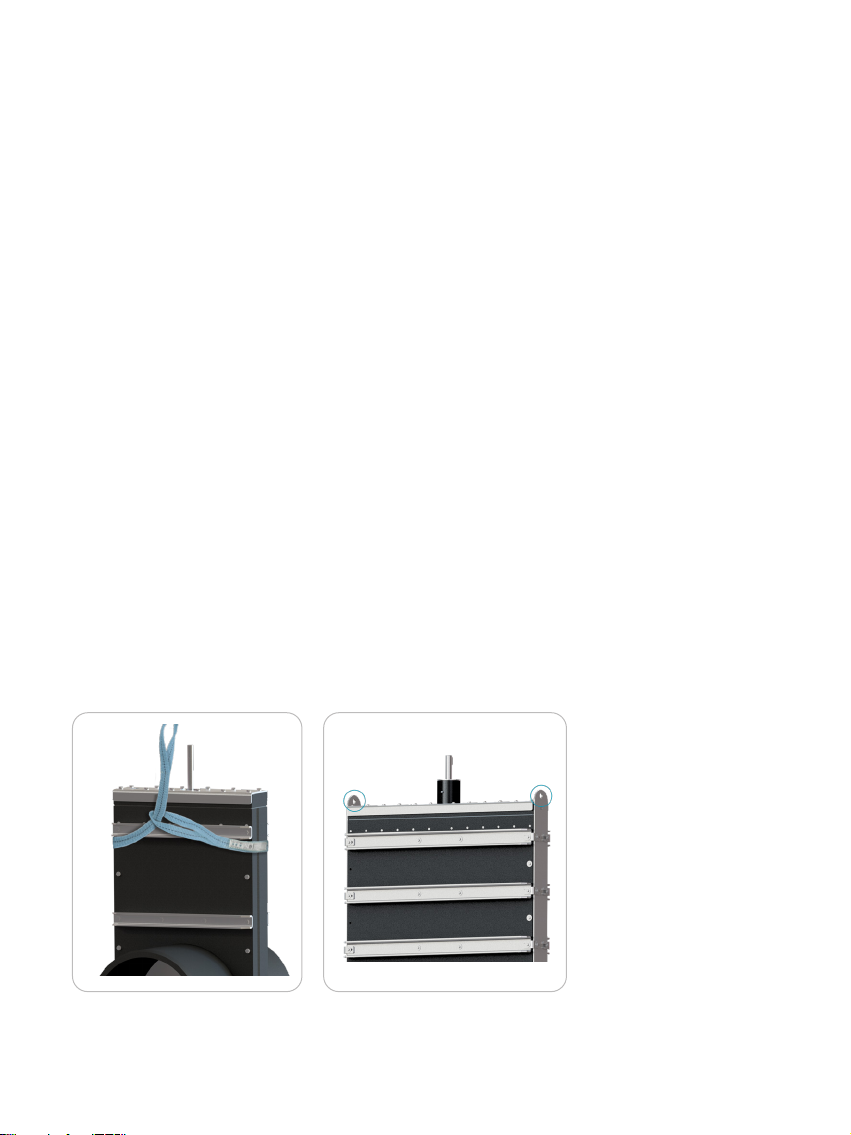
The device can only be moved on its original shipment pallet or using at least two of the lifting points on the outside of
the device (only applicable to valves too large to be handled by hand).
Lifting the product using any other method could result in damage to personnel or the device itself.

4
STORAGE
The product must be stored in a dry, well-ventilated environment, away from direct sunlight. Temperatures in storage
must be between -30°C and 40°C. The surface temperature of the plastics can´t exceed 80°C.
The device must not be flooded or otherwise submerged in water during storage.
If the device is stored outside for longer durations, it is advisable to cover up the inlet pipes to keep dirt and debris out, as
well as keeping wildlife from inhabiting the valve.
In areas with high humidity or with big fluctuations in temperature, the transportation wrapping must be removed to
avoid buildup of condensation. If the devise has an electric actuator it is advised to hook the actuator up to mains power
to allow the internal heater to keep condensation from damaging the circuit boards.
IDENTIFICATION
Do not remove the label. If purchasing spare parts, state the size and type of valve.
✔
= Recommended solution
= Possible solution
[ ] = Is not recommended
*As for further information and measurements, we refer to our product specifications
VALVE APPLICATIONS
The following table shows the applicable uses of each valve type, as well as which types of operation is available. If a valve
is used outside its intended application, proper function can´t be ensured, contact Wapro for advice.
SIZES USE MANUAL
OPERATION AUTOMATIC
OPERATION
SVL
RVL
SVL-T
SVM-TG
RVM-TG
Waste water
Clean water
Fish farming
On-Off
Spindle
Linak acurator
Auma drive
Hydraulic drive
Pneumatic drive
✔
✔
✔
✔
✔
✔
✔
✔
✔
✔ ✔
✔
✔
✔
✔
✔
✔
✔
✔
✔
✔
✔
✔
✔
✔
✔
✔
✔
✔
WAGATE® GATE VALVES [DN/OD] / [NPS/OD]
Made in Denmark
wapro.com
125/5”
315/12”
500/20”
800/32”
160/6”
355/14”
560/22”
900/36”
200/8”
400/16”
630/25”
1000/40”
®
Trademark registered in EUIPO
110/4”
250/10”
450/18”
710/28”
1200/48”
SVL
RVL
SVM-TG
RVM-TG
SVL-T
GV

5
MOUNTING
This manual should be read and properly understood before mounting. All personnel working with the device must be
familiar with the safety and warning instructions in this document.
MOUNTING DIRECTION
The valve must be mounted so that the arrow on the top of the valve or on the inlet pipe, follows the flow of the media.
Those valves designed for up- and downstream pressure, RVL and RVM-TG series are bi-directional and have no
specified mounting direction.
When mounted the gate valve must not lean more than 45 degrees from vertical in any direction. Violating this can
result in reduced watertightness, blockage of moving parts and permanent damage to the valve. If a mounting position
exceeding 45 degrees is needed contact Wapro for options.

6
SERVICE ACCESS
To be able to perform proper repair and servicing of the valve, a volume directly above the head of the valve equal to the
height of the valve body must be held free of other piping and components and so that it can be removed.
SUPPORT
DN 110-DN 315/NPS 4-NPS 12: Valves of these sizes are self-supporting and can be hung by their piping without further
support. If a valve is fitted with any type of actuator the valve must be supported as described for larger sizes.
DN 355/NPS 14 and up: Valves of these sizes are not self-supporting and must be supported from beneath. The flat
contact patch on the bottom of the valve is made to be the main support point for the valve.
The pipes connected to the device must be completely self-supported even when filled with water, and can´t transfer
loads into the valve.
The design of the piping system also must take heat expansion into account to make sure that expansion of the
connected pipe does not exert forces on the valve.

7
MOUNTING IN GROUND
All Wapro valves, except for those with actuators, can be mounted directly in soil. The valve should not be mounted
deeper than half of the valves pressure rating. Example: for a valve rated for 1bar of water pressure/10 meters of water
pressure the max depth in ground is 5 meters.
A large series of extensions of operation are available for all models. See general catalogue for options of contact Wapro.
When ordering note that the application is for in ground mounting.
MOUNTING ON WALL
Valves can be manufactured with flanges for mounting directly onto both flat and curved walls.

8
MOUNTING INTERFACE
The outlet pipes of the valve are made from PEHD100 and can be configured from the factory with either straight pipe
spigots, DIN flanges, loose DIN flanges, ANSI flanges or socket joints. For custom mounting solutions contact Wapro.
OPERATING DEVISES
All Wapro valves are available with a diverse range of operating devices. Both for direct mounting on the valve as well
as to extend the operation of the valve. Lengths are made to order. Note that as standard the valves come without any
operating device. Handwheel, extensions or other operating devises can always be ordered after initial delivery. Contact
Wapro and provide valve type and size.
If a operation extension is used, it is necessary to use wall brackets to eliminate excessive flexing. The brackets should not
be placed more than 1,5m apart.
AMBIENT CONDITIONS
The device is rated for use in temperature between -25°C & 40°C. If the devise is used below freezing temperatures the
buildup of stagnant water inside the valve is not allowed as ice formation inside the valve can permanently damage it.
RETROFITTING AN ACTUATOR
If the user wishes to retrofit an actuator, we recommend contacting Wapro for technical information on torque
requirements and interface measurements. If an actuator adapter is mounted, the interface on the device follows ISO
5211.
Valve with handle
Valve with extension
Valve with key top
Valve with bracket

9
COMMISSIONING
These steps must be followed closely before first use.
MECHANICAL SETUP
Before first use retighten all bolts on the valve following the table shown. Tighten the bolts in the head starting in the
middle and going around in a circular pattern.
The bolts can have gotten loose under transport and storage due to fluctuations in temperature.
After mounting is completed, slowly move the valve from open to closed. Make sure that there is no sudden resistance
to the movement which would indicate a problem.
Fig. 9.1
1
2
3
4
5
6
8
10
11
7
9
To complete commissioning the complete commissioning step in the operation manual specific to the actuator must
be completed.
ELECTRICAL ACTUATOR
The device can be equipped with different types of electrical actuators, most commonly from the manufacturer AUMA.
The connection diagram for the actuator differs between different specifications of the actuator. Therefore, a connection
diagram and complete manual is supplied physically with each actuator. If these documents are lost, complete
documentation can be downloaded from the following website: https://www.auma.com/en/service-support/wiring-
diagrams. The order reference for downloading can be found on the nameplate on the side of the actuator.
See pos. 2 on figure 9.1
TORQUE SPEC M6 M8 M10 M6 IN VALVE HEAD
7Nm 28Nm 50Nm 12Nm

10
SVL, RVL & SVLT
To close the valve push gently on the valve handle until a natural resistance is met. The valve opening is fully closed
slightly before reaching the end of the valves travel. Pressing hard on the handle will not improve valve performance and
can lead to permanent damage.
To open the valve, pull on the valve handle. The water pressure pressing on the valve can give a reasonable amount of
resistance to initial movement, but this is completely normal behavior. The valve is fully open when a resistance is met.
Never use heavy equipment to move the valve, as excessive force can permanently damage the valve.
If the valve is used in a setting with a lot of vibrations, like near a road, it is recommended to use a position lock to
mechanically lock the valve in place. Otherwise, the vibrations can make the valve slowly close over time.
SVMTG & RVMTG
To close the valve, turn the operating device clockwise until a natural resistance is met. The valve opening is fully
closed slightly before reaching the end of the valves travel. Applying high torque on the handle will not improve valve
performance and can lead to permanent damage.
To open the valve, turn the operating device anti-clockwise until a natural resistance is met. The water pressure pressing
on the valve can give a reasonable amount of resistance to initial movement, but this is completely normal behavior. The
valve is fully open when a resistance is met.

11
ELECTRIC OPERATION AUMA ACTUATOR, IF SUPPLIED
COMMISSIONING
Note that valves supplied with AUMA actuator will not be set up from the factory. To commission the valve either follow
the commissioning steps in the AUMA specific manual supplied with the actuator or get the local branch of AUMA to
carry out the commissioning. Contact Wapro for further advice.
LOCAL ELECTRIC OPERATION
To operate the valve using the selector switch [5] is moved into the “Local” position. Then, depending on the current
position, either button [1] or [3] is pressed to make the actuator move to the desired position automatically. The actuator
will stop when it has reached its programmed end stop. The movement of the valve can be stopped at any time by using
button [2]. At all times the current position of the valve can be seen on the display [6] as well as observing the mechanical
position indicators.
REMOTE ELECTRIC OPERATION
To operate the valve remotely the selector switch [5] is moved into the “remote” position. The actuator will no longer react
to the local controls and is controlled by the signals sent to it via its connection interface. The precise details of these
depend on the configuration of the actuator.
For more information on the connectivity and functionality of the actuator, we refer to the specific operation instructions
on the AUMA supplied along with the actuator.
MANUAL OVERRIDE OPERATION
To activate manual override, press the blue button at the center of the handwheel to engage motion. The handwheel is
rotated to move the core. The core rotes in the same direction as the handwheel, meaning that clockwise moment of the
handwheel results in clockwise movement of the core. The handwheel is rotated until the mechanical position-indicators
pop up showing that is desired position has been reached. Note that the correct alignment of the internal pathway is
only reached when the mechanical position indicator is at the peak of its movement.
Reactivating the electrical movement automatically disengages the manual override.

12
REMOTE ELECTRIC OPERATION
To operate the valve remotely the button [2] has to be pressed to get the controller into “remote” position.
The actuator will no longer react to the local controls and is controlled by the signals sent to it via its connection interface.
The precise details of these depend on the configuration of the controller.
COMMISSIONING
The valve with actuator and controller is delivered ready to use with the basic setup already carried out. For more
advised options, including remote control some setup is required. See the specific controller documentation for setup
procedures. The documentation can be found here: https://www.linakthirdparty.com/products/motor-controllers-and-
drivers/wcu/#/brochuresmanualsandbussetupfiles
LOCAL ELECTRIC OPERATION
To use the valve, the controller has to be in the “local operations” mode, activated by pressing the button [2] shown on
the figure below. Note that when in this mode remote controls are inactive and will only be activated by pressing the
[2] again.
To open the valve press and hold the “Up” button [1]. To close the valve, press and hold the “Down” button [3].
The current position of the valve is shown on the display [4], 0% indicates a fully closed valve and 100% indicates fully
open. The valve will automatically stop when it reaches its programmed end stop.
ELECTRIC OPERATION LINAK ACTUATOR, IF SUPPLIED
1 2 3
4

13
MAINTENANCE
• Inspect the devise for visual signs of damage. If any significant damage is found, please contact Wapro for advice.
EVERY 12 MONTHS:
• If supplied with AUMA actuator, the actuator has an internal movement counter to keep track of movements.The
gaskets should be inspected for wear or tears. This can either be done using a camera sent though the pipe system
or by disassembling the valve (Described on the following pages)
The following maintenance must be performed for the product to operate as intended. Failing to do so voids the warranty.
MAINTENANCE PLAN
Every six months:
• To check for proper function, a full open/close operation must be performed. Long periods without use can cause
the gaskets to get stuck in place. The valve should operate smoothly and without sudden resistance. Jerking
motion is a sign of sticking gaskets.
• Refill the bearing housing with bearing grease using the grease nipple. SKF LGWA 2/0.4 or similar is recommended
for 0-40°C. For temperatures below freezing a lower viscosity grease is recommended. (Only applies to SVM-TG
and RVM-TG sizes DN710/NPS28 and above)

14
MAINTENANCE INSTRUCTIONS
Disassembly of valve to change internal components or gaskets.
Note that this service must be done while the valve is not under pressure.
1. To make the service easier, the valve should be fully open before starting.
2. Remove the handwheel or any other operating device present.
3. Loosen the screws in the head of the valve.
4. Carefully remove the head from the valve. Be careful not to damage the seals in the head when removing the
head.
5. Unscrew the spindle from the spindle nut (only applicable to SVM-TG & RVM-TG)
6. If the gasket must be changed a thin piece of plastic has to be inserted into valve between the gate and the
gasket, before removing the gate. Otherwise reinserting the gate is impossible without damaging the gate. Gasket
chance is only possible on sizes DN400/NPS16 and up, and not on valves with double seals (RVM-TG).
SVM-TG and RVM-TG

15
WARRANTY
RIAWATECH A/S WARRANTY
RiaWatech will remedy defects in material and/or workmanship in any new RiaWatech valve for a period of two (2) years
from the documented date of purchase so long as the valve has been used in accordance with RiaWatech´s instructions
and recommendations and under normal operating conditions. The warranty does not cover damage to the valve
caused by external mechanical forces, such as interference from humans, animals or machines, nor is the warranty valid
if the valve has been modified or altered in any way post-production. Furthermore, the warranty is not valid (a) if the
valve is damaged due to exposure to high concentrations of chemical substances, (b) if the valve is damaged because
of pressure spikes, water hammering or vacuums exceeding the rated limits, (c) the warranty is invalid if flow velocity
exceeds what is recommended, and (d) if malfunctions are caused by other equipment.
To request warranty service, the buyer should contact the WaGate dealer where the valve was purchased within a
reasonable time after discovering any defects. The valve serial number or order number must be quoted in the case of
a warranty claim. RiaWatech´s liability is limited to the replacement or repair of the defective valve. RiaWatech will not
assume costs incurred for removal of defective valves or subsequent installation of replacement valves. Furthermore,
RiaWatech will not assume transportation costs of damaged valves or replacement valves. RiaWatech warrants that
repaired or replaced valves are covered for the greater of either the remainder of the original valve warranty or 90 days.
THE WARRANTY EXPRESSED ABOVE SHALL BE IN LIEU OF ANY OTHER WARRANTIES, EXPRESSED OR IMPLIED,
INCLUDING, WITHOUT LIMITATION, ANY IMPLIED WARRANTIES OR CONDITIONS OF MERCHANTABILITY, FITNESS
FOR A PARTICULAR PURPOSE AND NONINFRINGEMENT WHICH ARE EXPRESSLY DISCLAIMED, AND IS IN LIEU OF
ANY AND ALL OTHER OBLIGATIONS OR LIABILITY ON RIAWATECH´S PART. TO THE MAXIMUM EXTENT PERMITTED
BY APPLICABLE LAW, UNDER NO CIRCUMSTANCES WILL RIAWATECH BE LIABLE TO BUYER FOR ANY INDIRECT,
INCIDENTAL, SPECIAL OR CONSEQUENTIAL DAMAGES (INCLUDING ANY DAMAGE FOR LOSS OF REVENUE OR
PROFIT), OR OTHERWISE ARISING OUT OF OR IN CONNECTION WITH FURNISHING OF THE VALVES, PARTS OR SERVICE
HEREUNDER, OR THE PERFORMANCE, USE OF, OR INABILITY TO USE ANY OF THE VALVES, PARTS OR SERVICE, OR
OTHERWISE, WHETHER BASED IN CONTRACT, WARRANTY, TORT, INCLUDING WITHOUT LIMITATION, NEGLIGENCE
OR ANY OTHER LEGAL OR EQUITABLE THEORY. TO THE MAXIMUM EXTENT PERMITTED BY APPLICABLE LAW, THE
REMEDIES SET FORTH IN THIS LIMITED WARRANTY SHALL APPLY EVEN IF SUCH REMEDIES FAIL THEIR ESSENTIAL
PURPOSE. FOR THE AVOIDANCE OF DOUBT, NO EMPLOYEE, AGENT OR OTHER REPRESENTATIVE OF RIAWATECH IS
AUTHORIZED TO EXTEND OR OTHERWISE MODIFY THE WARRANTY SPECIFIED HEREIN.
SVL and RVL

Rev 1.0
CONTACT WAPRO
customerservice@wapro.com
wapro.com
SE: +46 (0)454 185 10
DK: +45 64 82 40 00
US: +1 888 927 8677
UK: +44 114 308 0123
This manual suits for next models
8
Table of contents
Other WAPRO Control Unit manuals
Popular Control Unit manuals by other brands

Konica Minolta
Konica Minolta IP-411 user guide

Mircom
Mircom QIF-2011 installation instructions

McConnel
McConnel 5 Service XTC Mk2 PROPORTIONAL SWITCHBOX... quick start guide

AWS
AWS 915 Operating instruction

Flo-Tite
Flo-Tite MPF15 Installation operation & maintenance

Telit Wireless Solutions
Telit Wireless Solutions ME910C1 Series quick start guide